Useful links
comments
- Fab BCN Awesome resources ✔
- How cutting Copper with the Vynil cutter ✔
- Ideas for Creatives Lamps ✔
- Living Hinges ✔
- Crop Image with InkScape ✔
other comment
This week: parametric modeling and laser cutting review, we finally get our hands on a machine. Follow me on this exciting journey of the week.
I finally arrived in Barcelona, met the instructors and my classmates and honestly I immediately had a great impression, I feel lucky.
Do you know what was the worst part of this week's assignmentS?
Finding a stable accommodation for the next months while in the meantime living in a hostel, indeed, I am writing these same lines in the lobby of Safestay [excellent hostel, It's not an affiliate link :) ] among chatting people from various countries.
Now let's see what I was able to do concretely:
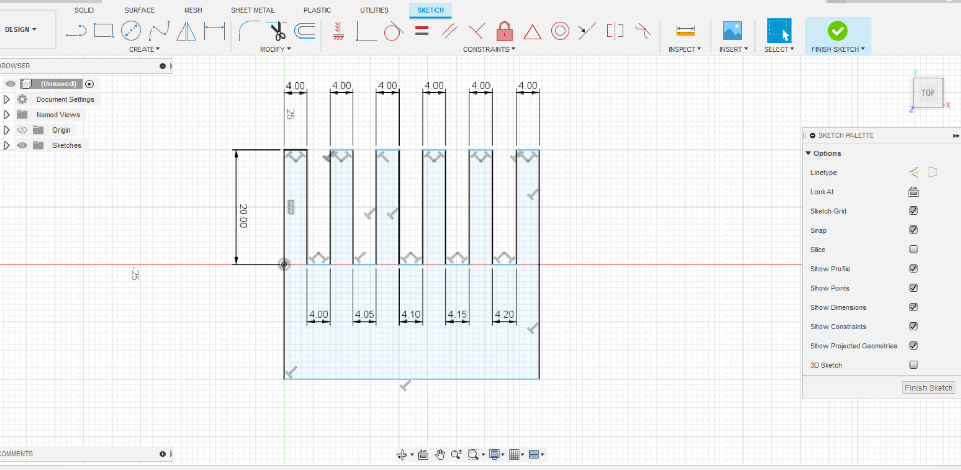
During the group exercise (of which I speak explicitly on this page [link]) it was decided to create the model of a comb that we would then make with the laser cutting machine.
The peculiarity of this comb is that the gap between the teeth should have been variable and controlled parametrically. Specifically the gap lenght should have been incremental each time by a delta (which we set to be 0.05 mm).
So for example the first gap lenght should have been x + delta, then x + 2delta, then x + 3delta and so on.
Below I report the image of the object as we intended to design it.
This problem, which apparently seemed easy to solve, instead proved the opposite (at least for me).
In the next paragraphs I present my solutions, with attempts and partial failure ..or partial success if you are optimistic :)
Unfortunately Fusion 360 doesn't allow to set expressions such to have an increasingly recursion the way I wish for the comb project.
So a first solution that came up to my mind is to divide the comb into recurring geometries, draw the sketch of one (therefore on a plane) and then repeat it on the three-dimensional plane, as it is explained in the following images:
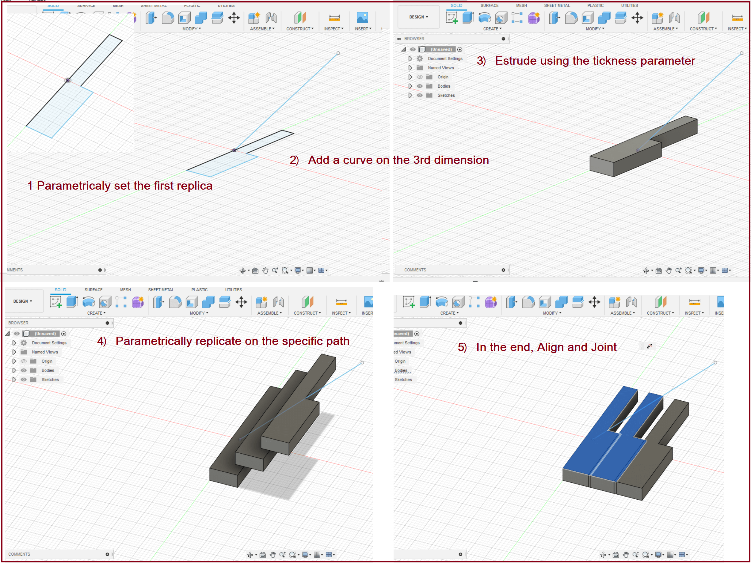
Once the objects (body) have been replicated three-dimensionally on a specific curve (in this case a straight line), then they can be aligned projecting them back onto the plane with the Align command and finally jointing them to have the desired product.
On a parametric level I can control the replicas on the curve which I then project on the XY plane.
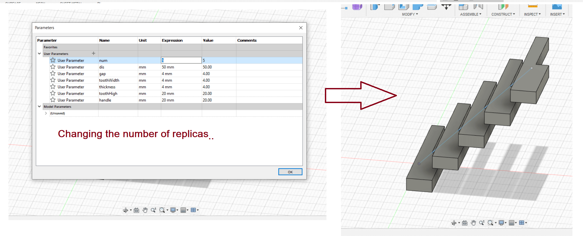
There are obviously several drawbacks with this method that prevents us from giving the desired result:
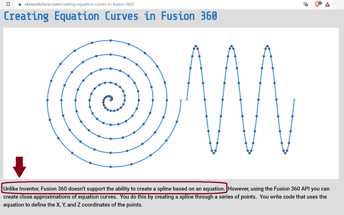
The first: In order for the projection of the individual replicas to be spaced by an incremental delta, the replicas cannot three-dimensionally lie in a straight line but it would take a curve with a specific equation (an algebraic type equation of a certain degrees), in our case instead the projection of the replicas resulted to be clearly equally spaced.
Unfortunately when looking for the option to create curves derived from equations in Fusion 360, I came across this:
Second problem; Even if I had Inventor and managed to get the right curve, there is still another issue: The Align command. That's a command that unfortunately works on two "bodies" at a time as far as I understand. This means that even if I increase the replicas parametrically then I would still have to manually align all the bodies, making all the process very inconvenient.
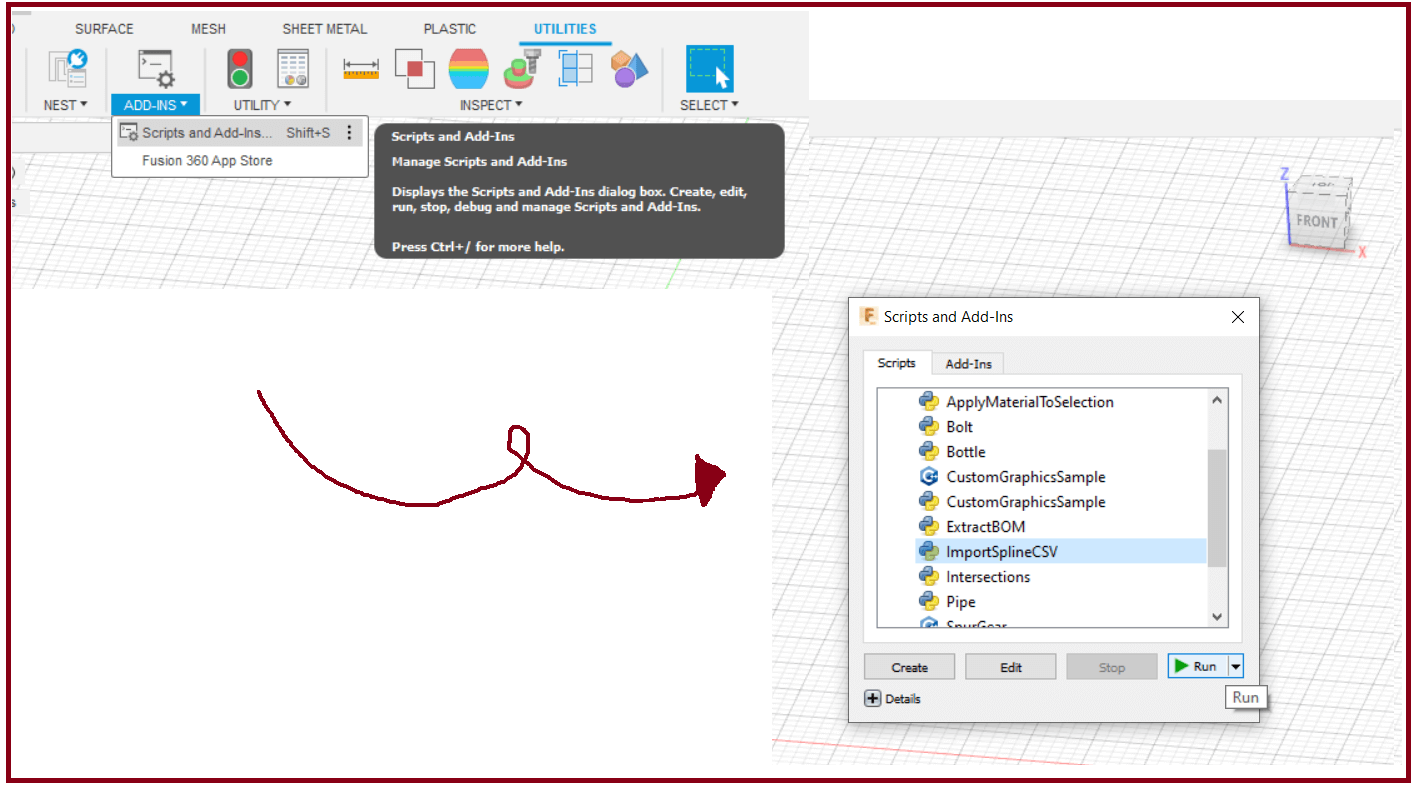
From Week 2, I discovered that Fusion 360 has Add-ins which are simply applications to generate models automatically.
One of these is ImportSplineCSV, as the name implies, you import points from a spreadsheet that Fusion360 draws and then connects them all with a spline.
The idea is therefore to parametrically program the spreadsheet and then import the shape of the comb to Fusion360.
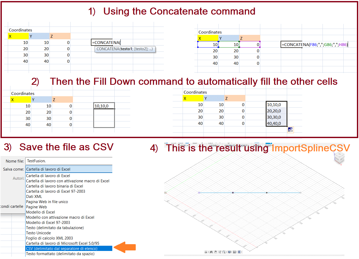
Note that the spreadsheet must be saved with the CSV extension and that the 3 points representing the X, Y and Z coordinates must all be entered in the same row separated only by commas.
The latter can be easily achieved with the Concatenate command directly from Excel, as shown in the images below.
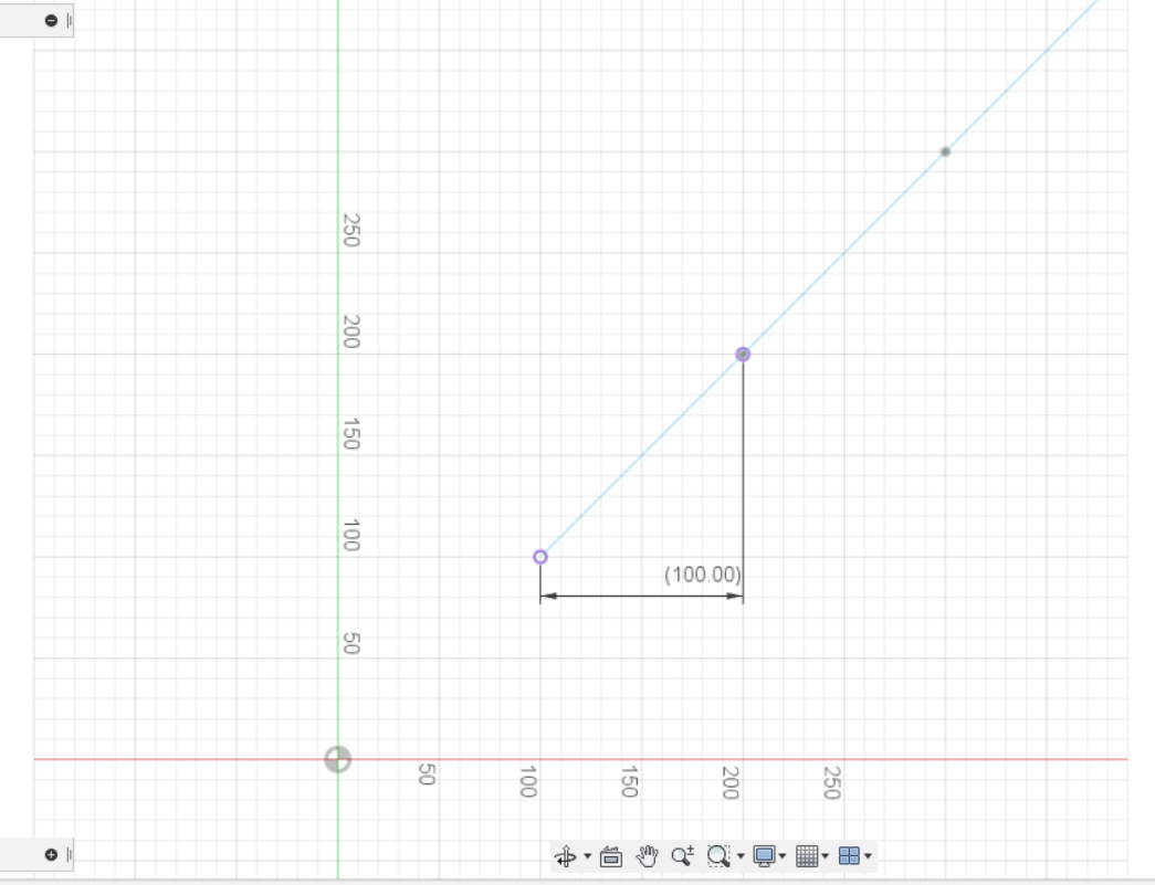
Be careful about the dimentions, beacuse when you import points the program treat them in Centimeters NOT millimiters.
You can easily program a spreadsheet by creating appropriate links between the cells, once you have created a first group of points connected to each other with specific rules
(where these groups represent the first tooth of the comb plus the space next to it) then you can easily generate the other groups of points using the Fill Handle command as Excel recognizes the pattern you want.
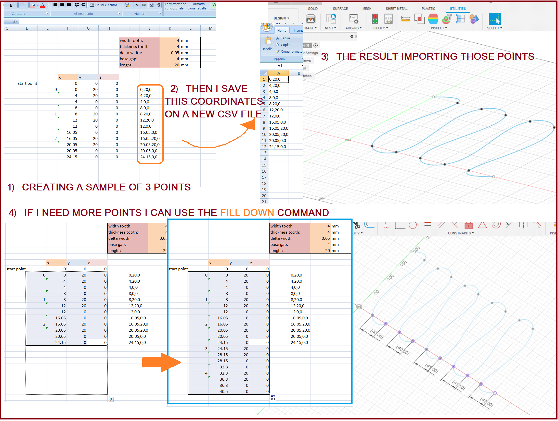
This way, with just a quick mouse gesture I generate the points I need that can be changed parametrically through the box cell in the up-corner.
all the point change accordly
The first result was not satisfactory, as the spline is NOT a set of lines but has its own roundness.
To avoid this issue I had to add many more points to the excel sheet and finally below I show you the result. Unfortunately it remains approximate as you can still notice some irregularities when zooming in
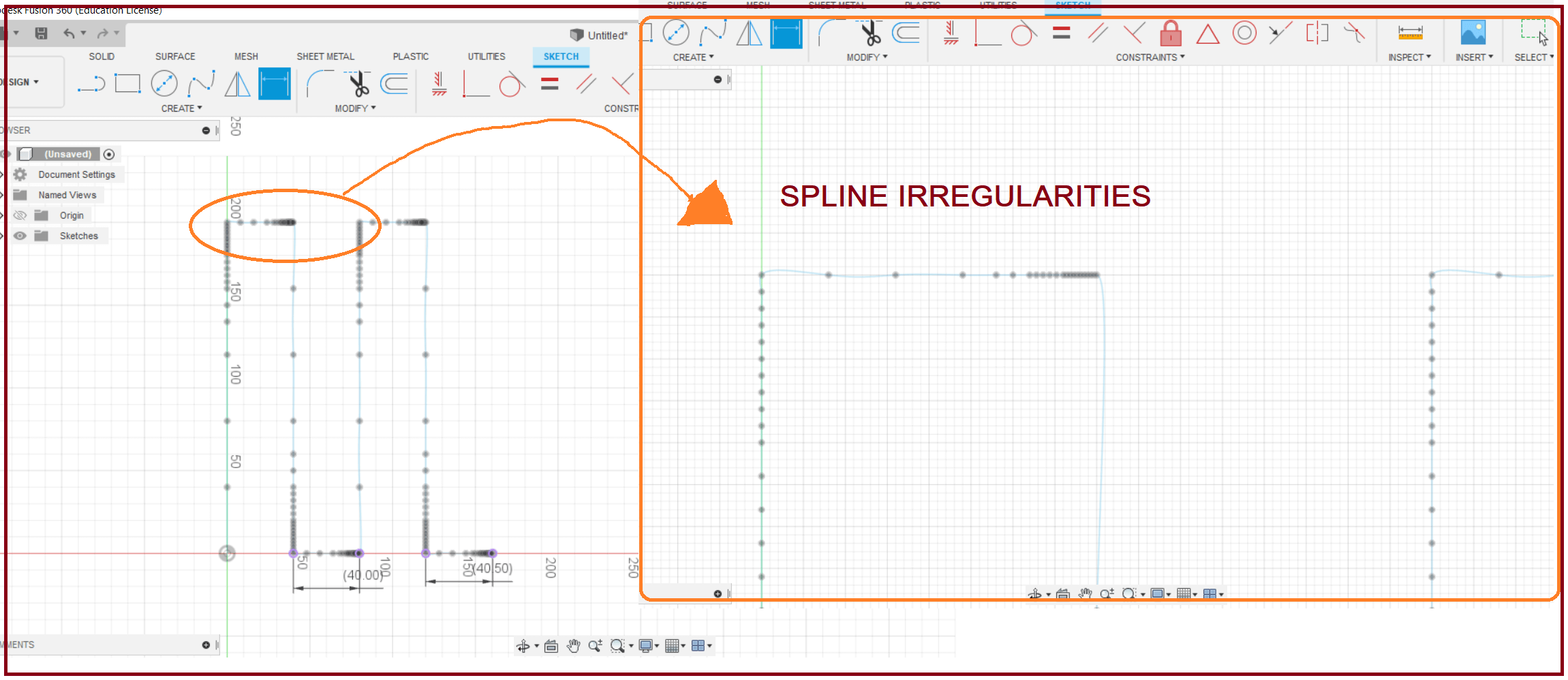
Also, there is another problem: Adding to much points to the Excel sheet makes the work long and time-consuming, therefore too inconvenient to be usable.
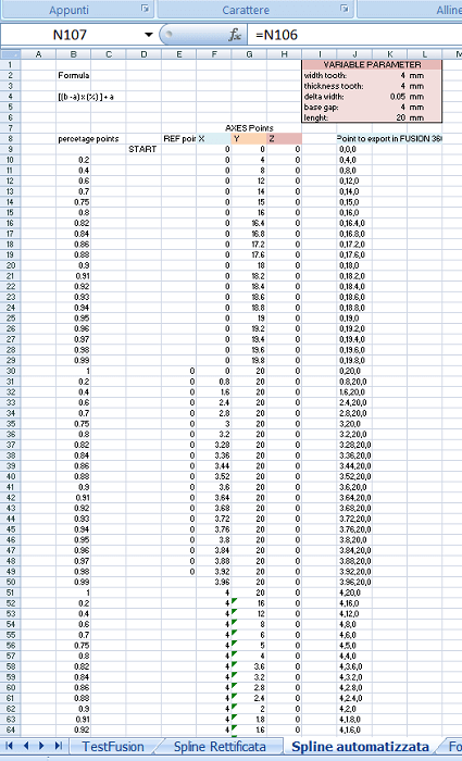
The image above shows A PART of the enormous set of points to just create the first replica of the comb (first tooth plus first gap)
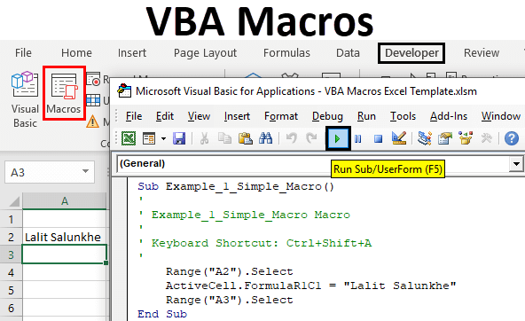
Even if not very efficient I still see the way through the spreadsheet as a valid method to accomplish this issue: I believe that one solution would be to use of the MACRO (VBA). This is a kind of programming language to generate the points. Too bad it is a subject that I do not know yet, which I would have liked to investigate but I did not have the time to do it.
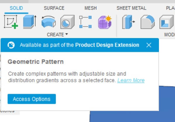
Another option would be probably the brand new Fusion360 feature (set up just more or less a week ago) called Geometric Pattern. But this must be studied well too.
Finally, there would be OpenCad software which intrigate me and I'm quite sure it could perhaps give me an easier solution cause its totally different command/control structure compared to other CADs.
Not having an appropriate parametric Comb design, I had to switch out and think about something else to do in order to practice with the laser cutter.
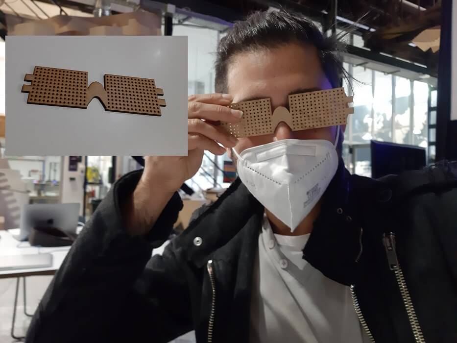
I ended up parametrically designing a pair of Stenopeic Glasses, also known as PinHole Glasses. I made those I made them thinking of something useful for me, especially in this very chaotic period, where I started to follow the course in person and in the meantime I used all my free time glued at the screen of my computer to find a place to live.
My eyes indeed have become too tired, and my vision has become much less sharp because of that (I hope such as a temporary effect!!).
These type of glasses, which has no lenses but as the name implies just holes, allow you to see better in these circumstances and everything works for a simple optical effect.

That's because through the holes passes only the component light that is orthogonal to the eye, so filters the oblique components that are those that can make blurry what you see.
I made everything parametrically, so if you change the number of holes they still fit perfectly into the size of the lens.
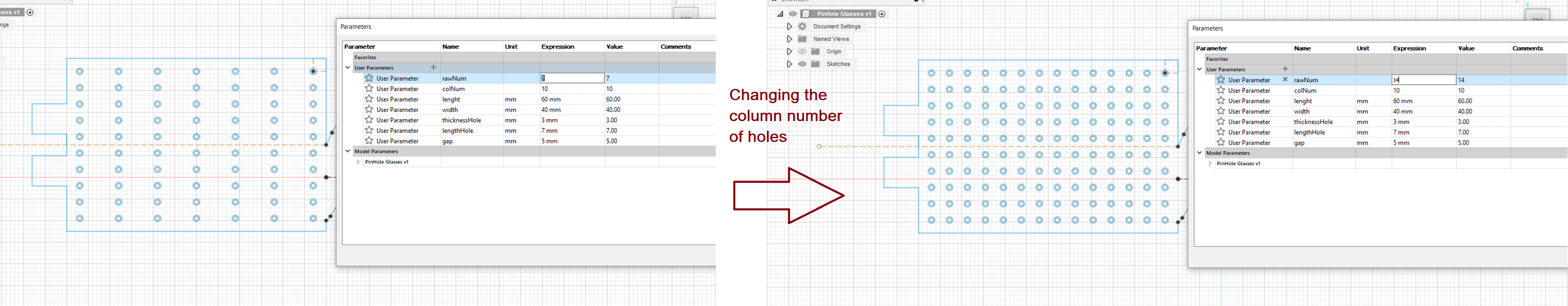
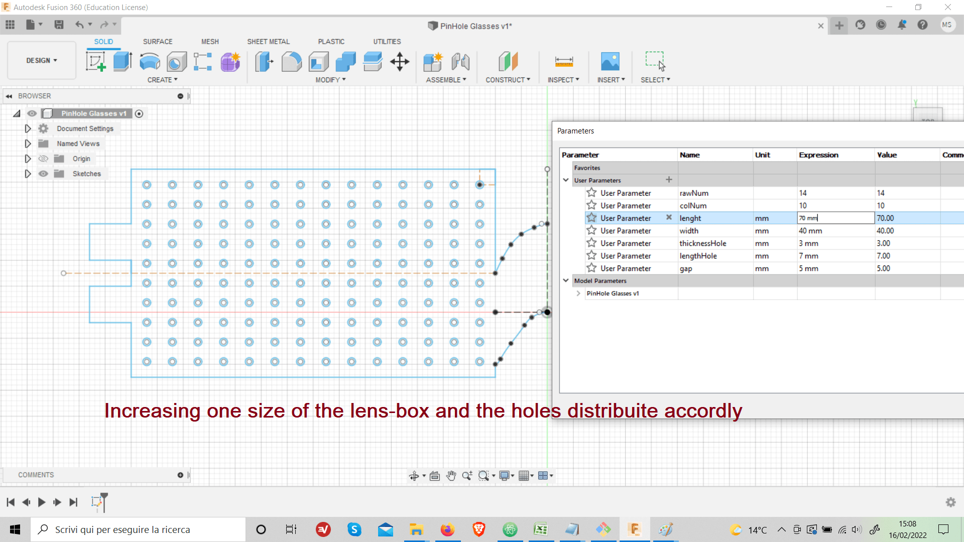
While if I change the size of the lens, the holes always remain equispaced with a greater or less distance depending on whether you have increased or decreased the size of the lens.
Here you are, a preview of the final result:
Once the model has been prepared, it must be exported as a .dxf file. Then we move on to the machine, in the Barcelona FabLab I've been using 2 machines mostly: Trotec 200 and Trotec 4000.
We use Rhinos as a software to load the .dxf file and then print it, so it's worth point out and list in more detail some meaningful commands we are going to use to prepare the Laser Cutting.
| Distance | To measure point to point distance, remember to hide the measurement otherwise it'll be printed as well |
|---|---|
| Boundingbox | To know the overall dimension of your 2D model, and indicate also the z size that must be 0 |
| Scale | Select from the origin point to reference point, than scale. Very useful as I have often had sizing problems importing files from Fusion360 |
| Copy | Copy an object. |
| Array | To replicate an object through a pattern. |
| SelColour | By first clicking on a line of a specific color and then using this command, all lines of the same color as the one you previously selected are now automatically selected as well. |
| Join /Explode | To unify solid lines so that the laser follows a continuous path and does not randomly cut lines, which it can be problematic if then the material moves during the process. (Explode does the opposite) |
| Hide / Show and Isolate | To hide, show specific lines and objects. |
| Text | To put text on an object. |
| Hatch | Command to fill the writing or a selected object with a color (black is the default color). |
| Osnap and Gumball | Not a command, but a clickable option in the bottom menu. |
Once the model is adjusted, you can colour the lines and curves in the model. The most used colours are Red, Blue and Magenta as they are the same colors that the laser cutting control software recognizes.
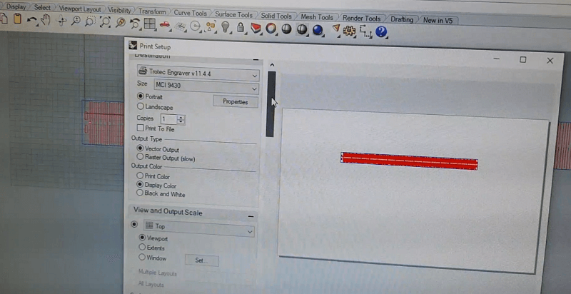
After this, click on print (or Ctrl + P), the print screen appears where you can control some parameters (such as the scale factor which must be 1:1), if everything is in order, proceed and the model is loaded on the machine software.
From here you drag the model to the central workspace and you can snap it directly to the pointer representing the machine's laser position in the work surface.
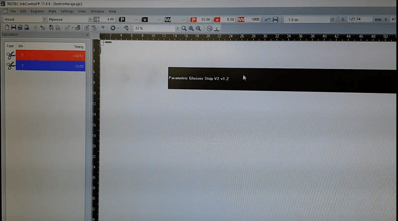
Go to Setting -> Change colors, to bring up the colour setting menu. Here for each color you can choose if you want to cut or to engrave, note that the laser will start from the first ones colors in the list (if selected). Then you can also set other parameters as Power, Speed and Frequency of the laser.
Each material needs different values if you don't have any clue what kind of values you need you can either try on the left menu where you can find some pre-set materials values, either use a table of very useful reference here in the FabLab.
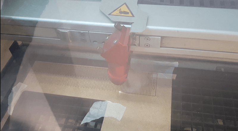
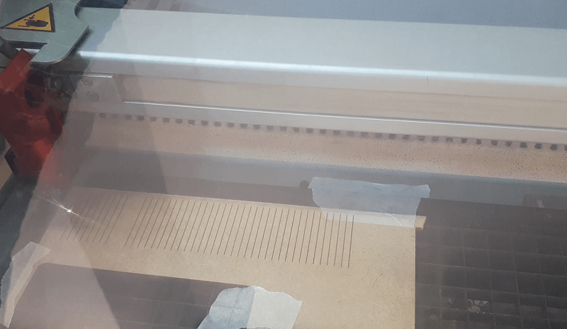
Once this is done, we move on to the machine side.
The most important things are to calibrate the laser focus, and it's very easy to do with the caliber and also never forget to keep the fume extractor turned on while the machine's running.
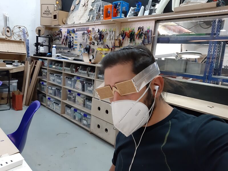
I hooked a folding strip to the pinhole glasses, I am very satisfied with that, the first attempt turned out to be good, as the parameters I choose gaves the strip a good flexibility and a good resistance as well, in fact I can easily wear them with out the fear to brake them.


The next step was to try acrylic, and the qualities of flexibility and resistance remained the same. Plus having a much cooler effect now!
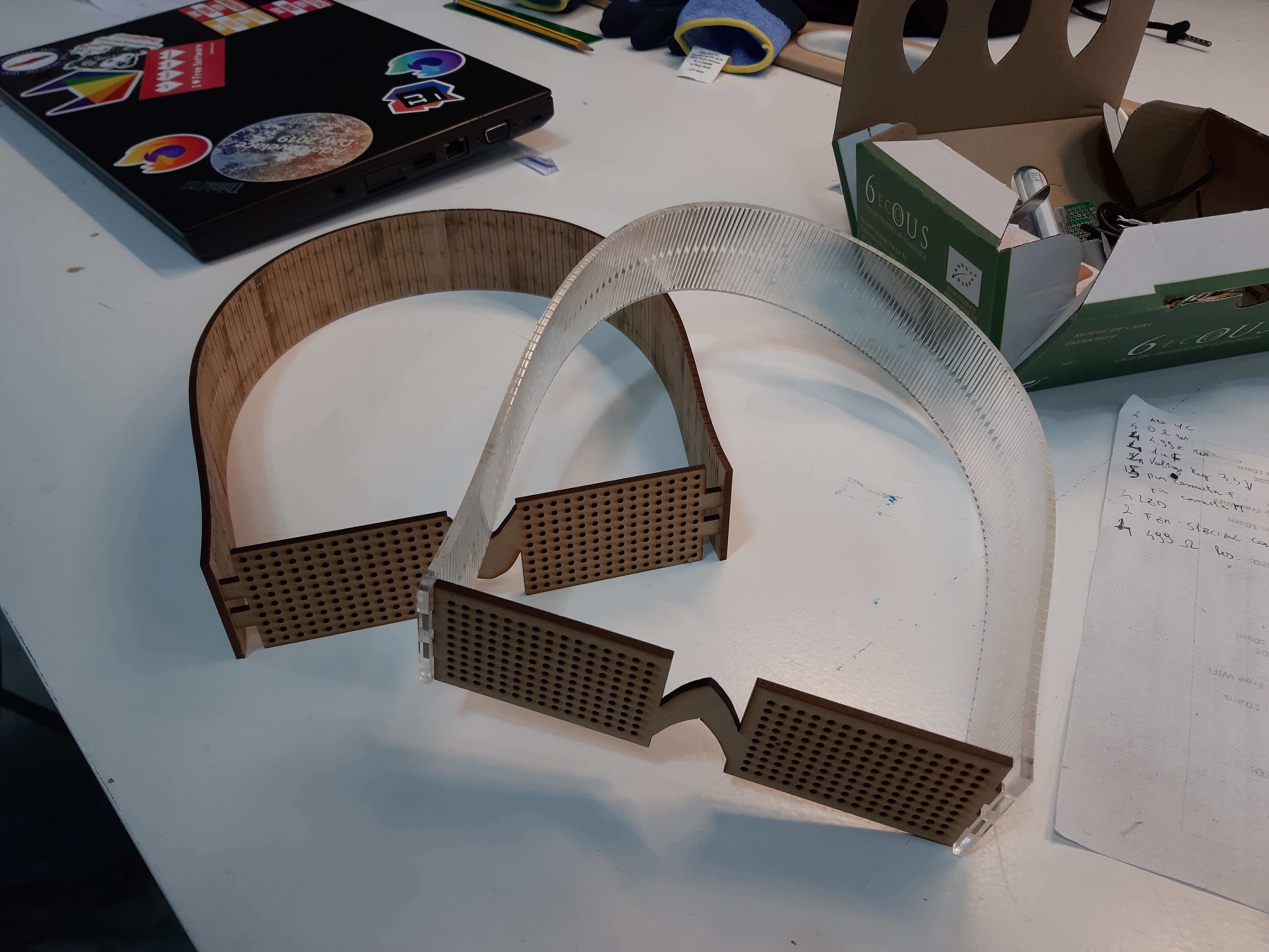
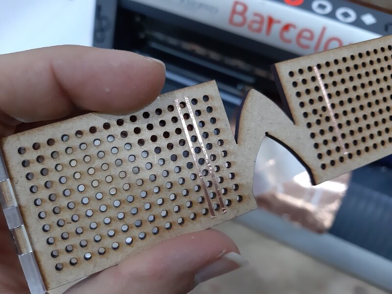
I wanted to give to my brand new glasses a WOW effect, adding LEDs and connecting them using Copper Paper traces I'd make with the Vinyl Cutter.
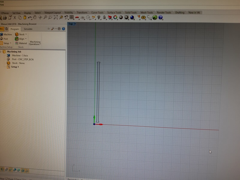
So I first designated some traces with Fusion360 and then I moved on to set up the machine.
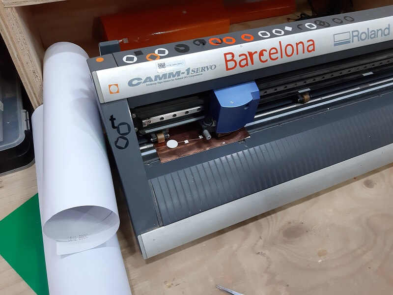
Each machine has a lever to load and unload the material to be cut, in my case, as I announced, I used a copper paper so that I could solder on it.
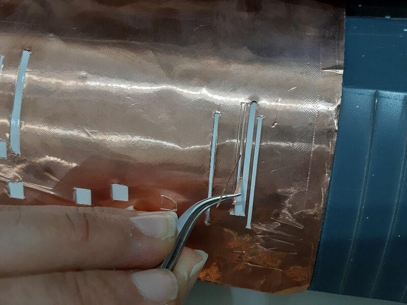
The next step is to do several tests, in my case, the hardness of the material and especially the minimum size of my model (we are talking about strips of 1 mm wide) made the job not so easy.
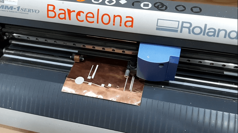
My instructor Josep and I were forced to make several attempts before getting a valid result. At first we gradually increased the strength, reaching the value of 200 gf. We have also reduced the speed to the minimum possible: 1 cm/s.
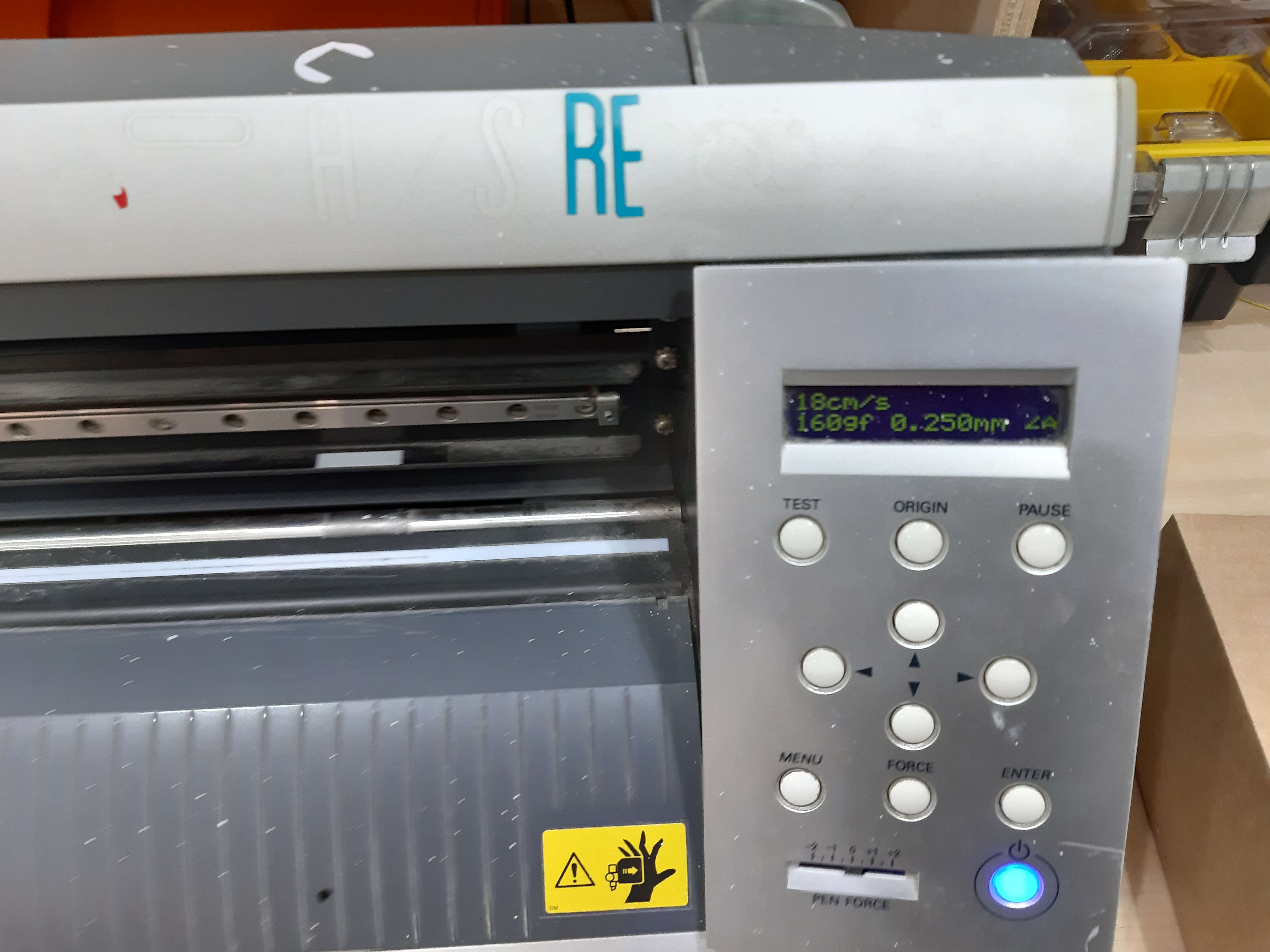
Even with these setting, it was still inconvenient to cut a set of strips together because of the high probability of ending up ruining them, so I ended up cutting one by one, but the result was ultimately acceptable.
This is the mesmerizing result adding a buntch of Blue LED: