Useful Links
- 3D print troubleshooting Guide ✔
- Step By Stap 3D Print Calibration ✔
- Materiom, 3D biomaterial recipes ✔
- Marlin G-Code Guide ✔
- G-Code Guide ✔
other comment
Ideas materialized in 3 dimensions, this week we talk about 3d printing and 3d scanning.
Regarding 3d printing, I already have a minimum of experience having bought my first 3d printer a couple of years ago, It's an Anycubic i3, where I mostly printed models downloaded from Thingiverse, while a few times I made personal projects as I showed in Week 2.
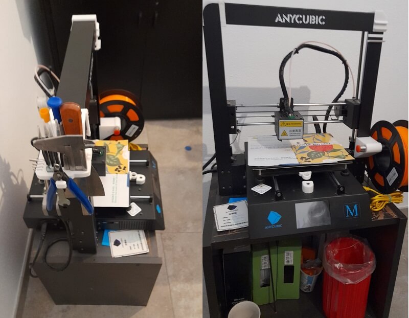
Having a Cartesian type printer I was already quite familiar with the concepts of Calibrating the work plane, unclogging the nozzle, changing parts of the machine like the nozzle itself and some switches and also setting the right parameters on Ultimaker Cura (the Slicer software) to obtain a decent print.
Our instructor Eduardo was in charge of explaining the lesson, and it was very interesting. Among the most important concepts:
Furthermore, the very known problem of printing time which can be limited with some precautions, such as decreasing the height of the layer (at the expense of the print resolution) or by increasing the movement speed of the nozzle (at the expense of any defects that could occur on the model) or by increasing the amount of extruded volume by changing the type of nozzle using for example the volcano type or super volcano (obviously at the expense of a greater use of power which would then serve to heat the nozzle itself). In short in 3d printing it's all a trade-off.
He also presented us with a very useful website to calibrate at the best you 3d printer. On the page there is a guide with several tests to do to best calibrate each specific section of the machine. One thing I will definitely do to my Anycubic when I get back home.
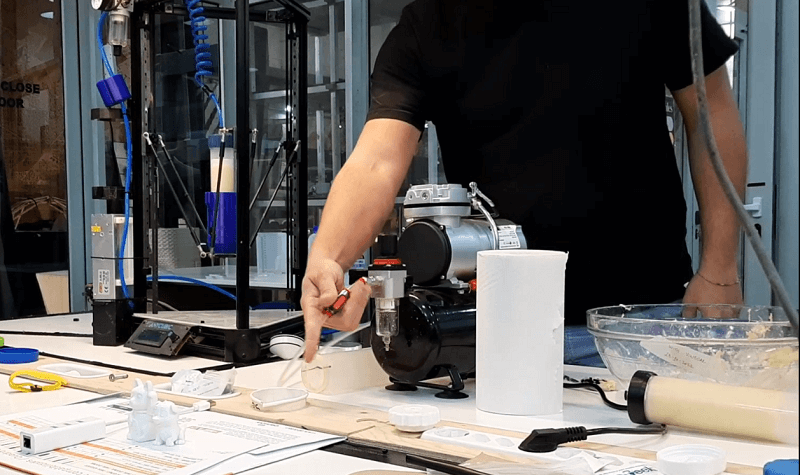
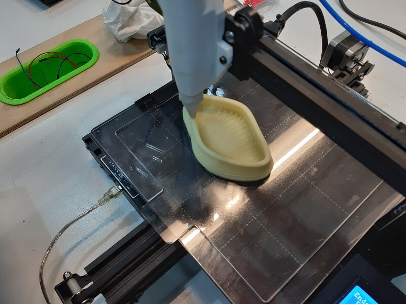
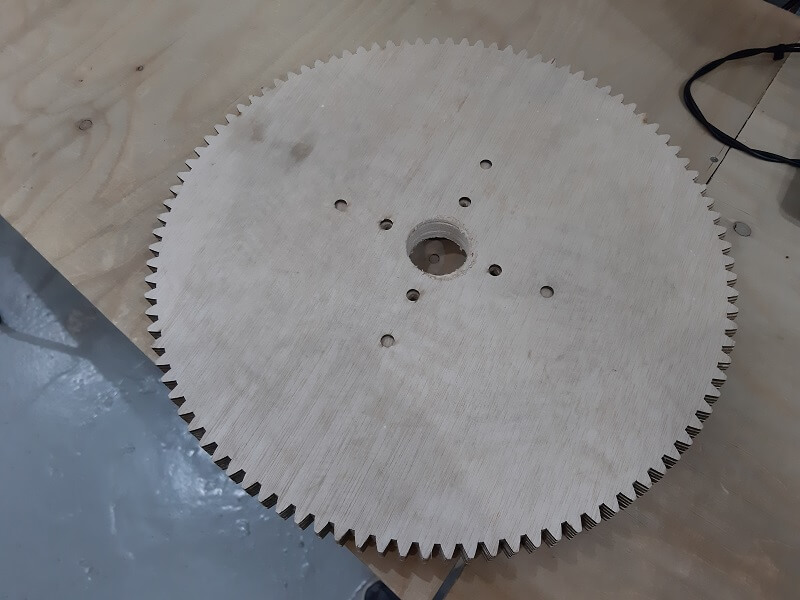
As far as I see, the Barcelona Fablab is specialized in researching different materials for 3D printing outside of the classic PLA and ABS. In fact, we were introduced to a special 3d printer with a modified nozzle to print different types of dense paste. In our case there was a smashed potatos paste mixed with some additives to make the paste properly sticky.
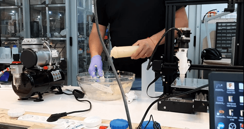
However, if one would like to have fun and test different materials, I recommend the website Materiom website to find 3d print bio-solution that worked good.
Obviously in order to use this type of printer we cannot simply slice it with Cura sw which does not have a proper option to select this unusual material as filament. So we swiched to another sw, called Repetier Host Software, where, aside for being a slicer, it is also possible to directly enter the G-code to control the machine.
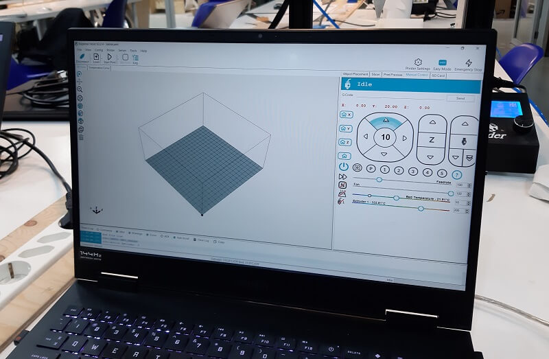
G-code is the operational language for CNC machining. It tells numerically controlled lathes and machining centers how to move tools in order to perform various cutting operations. It is equivalent to manual programming where each operation is spelled out line-by-line and is separate from M-code and T-code, codes that control the machine and tooling.
Here is a page directly from the Barcelona fablab[link] which is useful as an introduction to the topic.
To have a complete guide of all the actions that a 3d printer and their respective G-codes can do, there is the very useful website: Marlin G-Code Guide.
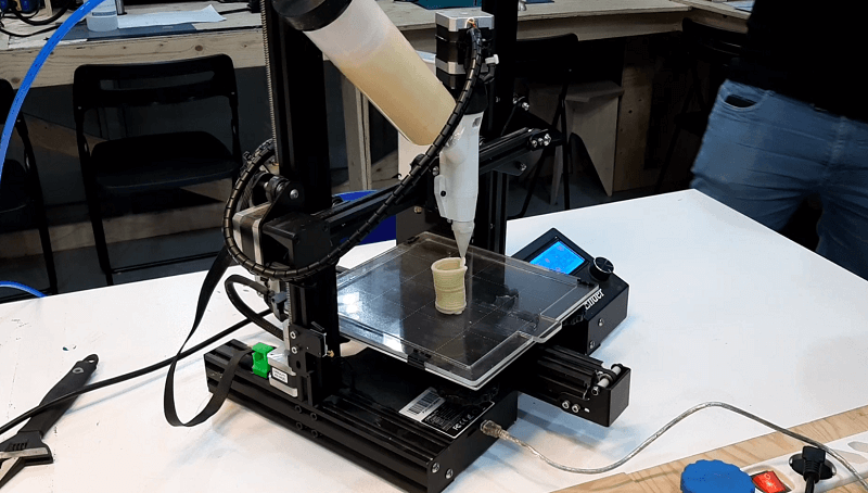
To get the G-code we used Rhino and a Grasshopper program already prepared by our instructors, in short with Rhino we built the shape we wanted to print, while with the grassHopper plug-in we obtained the G-code that we directly inserted in Repetier Host, then once set the BaudRate at 11500 we started the press.
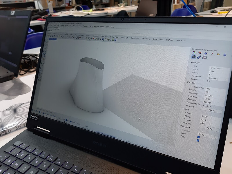
I want to thank Dhanu for collaborating with me in this useful exercise. Without her, who has experience in Rhino and Grasshopper, I wouldn't have completed the task.
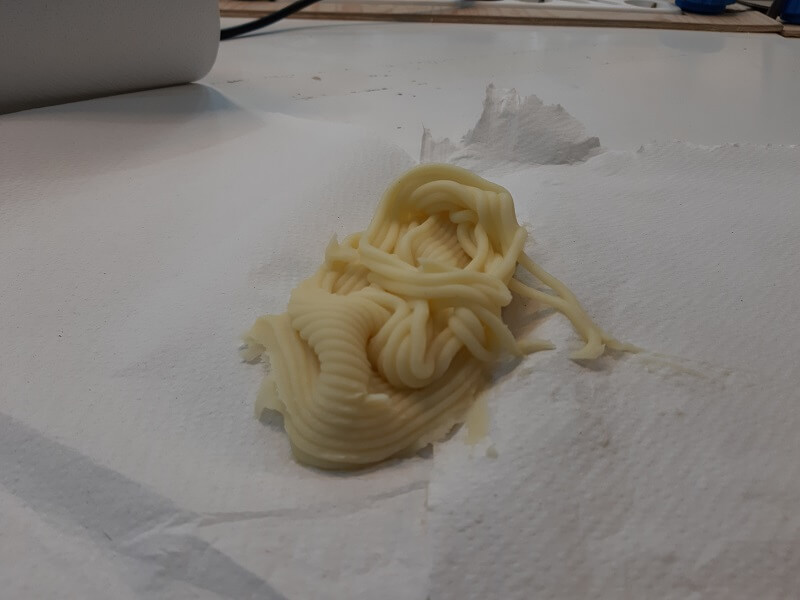
Unfortunately at a certain height the model collapsed on itself. The result, however, was very instructive.
The next topic of the assignment was 3d scanning, we were given a very broad overview of tools and software to scan at best from the smallest objects to huge buildings.
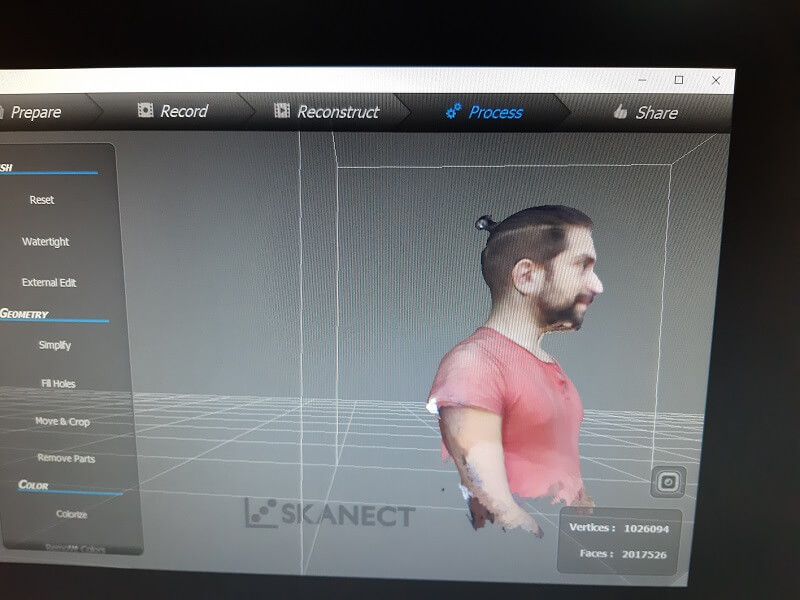
For my test I used the most economical and practical Kinect and the related software Skanect
The important thing to remember about scanning is the more data you collect the better the final result will be, this means collecting lots of images from lots of angles that must necessarily overlap. To proceed with my scanning I got on this rotating platform, so that a colleague of mine used the sensor for scanning while another colleague was turning me around.
Here is the final scan, there are certainly flaws but I am satisfied.
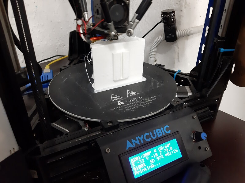
For my printing assigment I decided to use a Delta type printer, having already experience with the Cartesian type. Specifically, I used the Anycubic Kossel Lineas Plus printer.
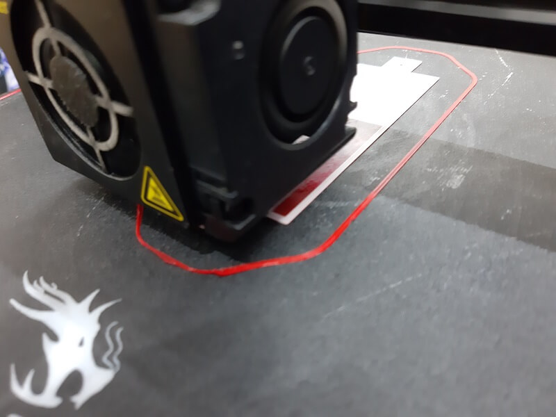
But before talking about my printing project, I want to tell you about all the countless problems I had to calibrate the printer worktable. Problems that cannot be solved simply turning some screws as in the case of the Cartesian printers, but a quite long process. First you need to use a suitable sensor, as presented below.
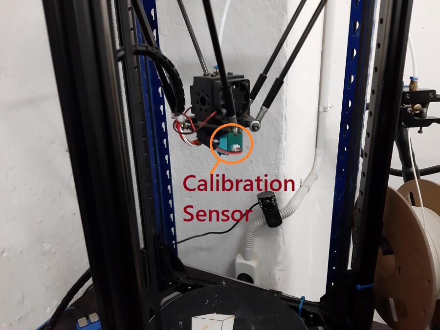
Here is shown how it works:
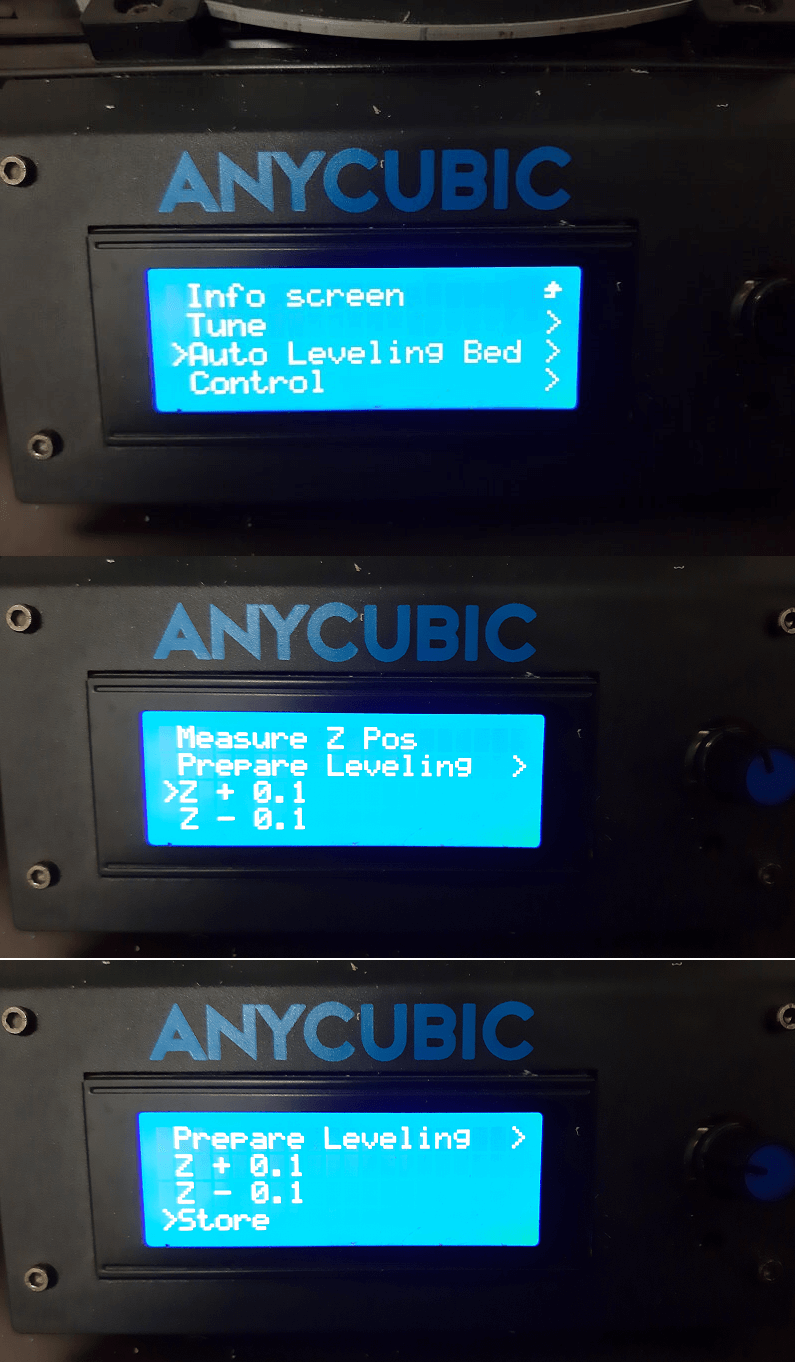
Once this is done, the print can be launched, but the offset of the Z axis will still need to be adjusted, this can be done easily even during printing via the panel control.
In particular you start from the Auto Leveling Bed and click on Z +0.1 mm or Z -0.1 mm to raise or lower the Z level to an optimum state, once that is done Click on Store to save the new offset.
As a printing project I want to create a support that holds an LED matrix to a VR case, practically one of the ideas I listed in the week 0 paragraph. What will be the aim of this thing and what it will be for will be revealed in the future... stay tuned :)
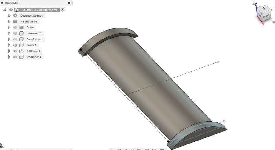
I made a first model with Fusion360, the intention was to have three pieces that would fit together.
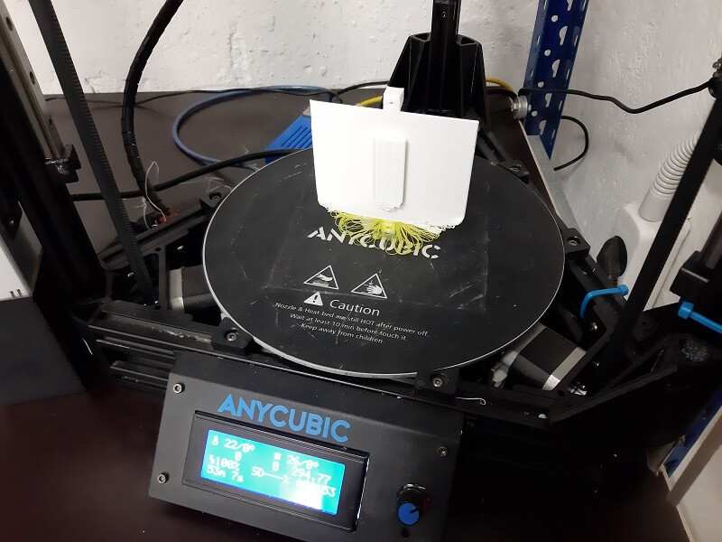
Then I 3D printed them:
The results, however, were disappointing, the main problem were the tolerances of the models and the pieces did not fit perfectly with each other and with the LED matrix itself:
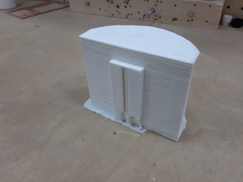
The different color depends on the rest of colored filament that someone else promptly left in the prints before mine. The main reason of my failure is rush to complete the assignment as fast as I could, then my instructor Eduardo enlightened me with the sentence:
"Marco, the problem is that you want accurate and fast that are the opposites in the 3D printing world"
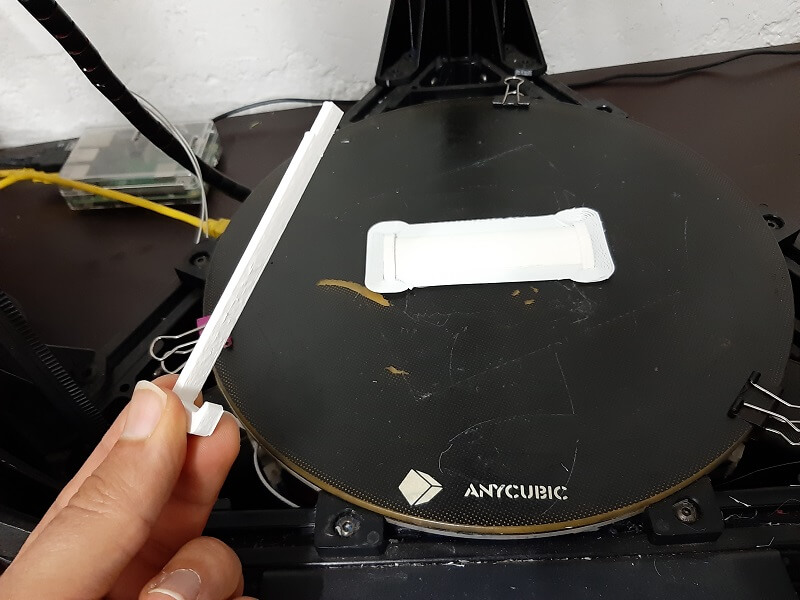
So I started over this time creating small pieces just to be able to have quick test-prints and rapidly check tolerances.
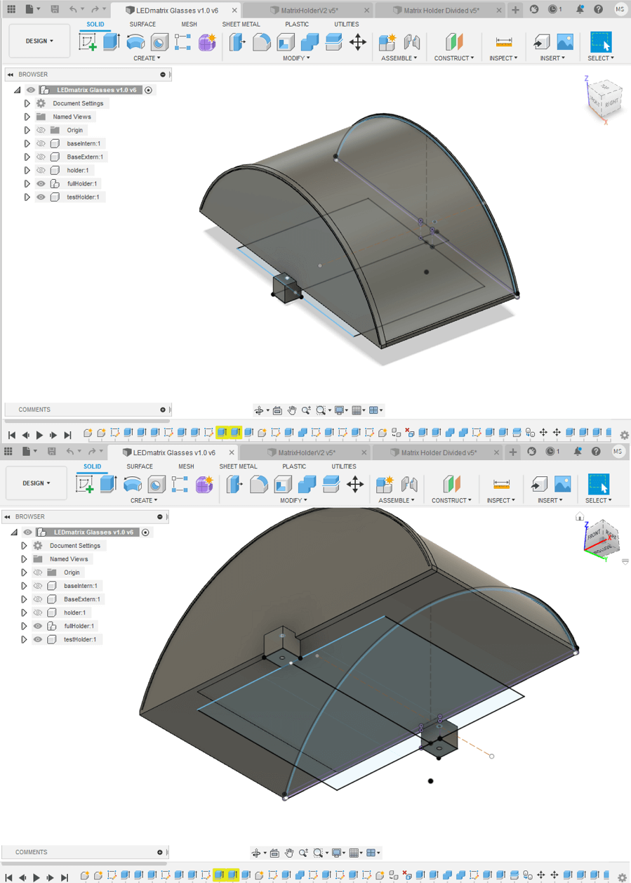
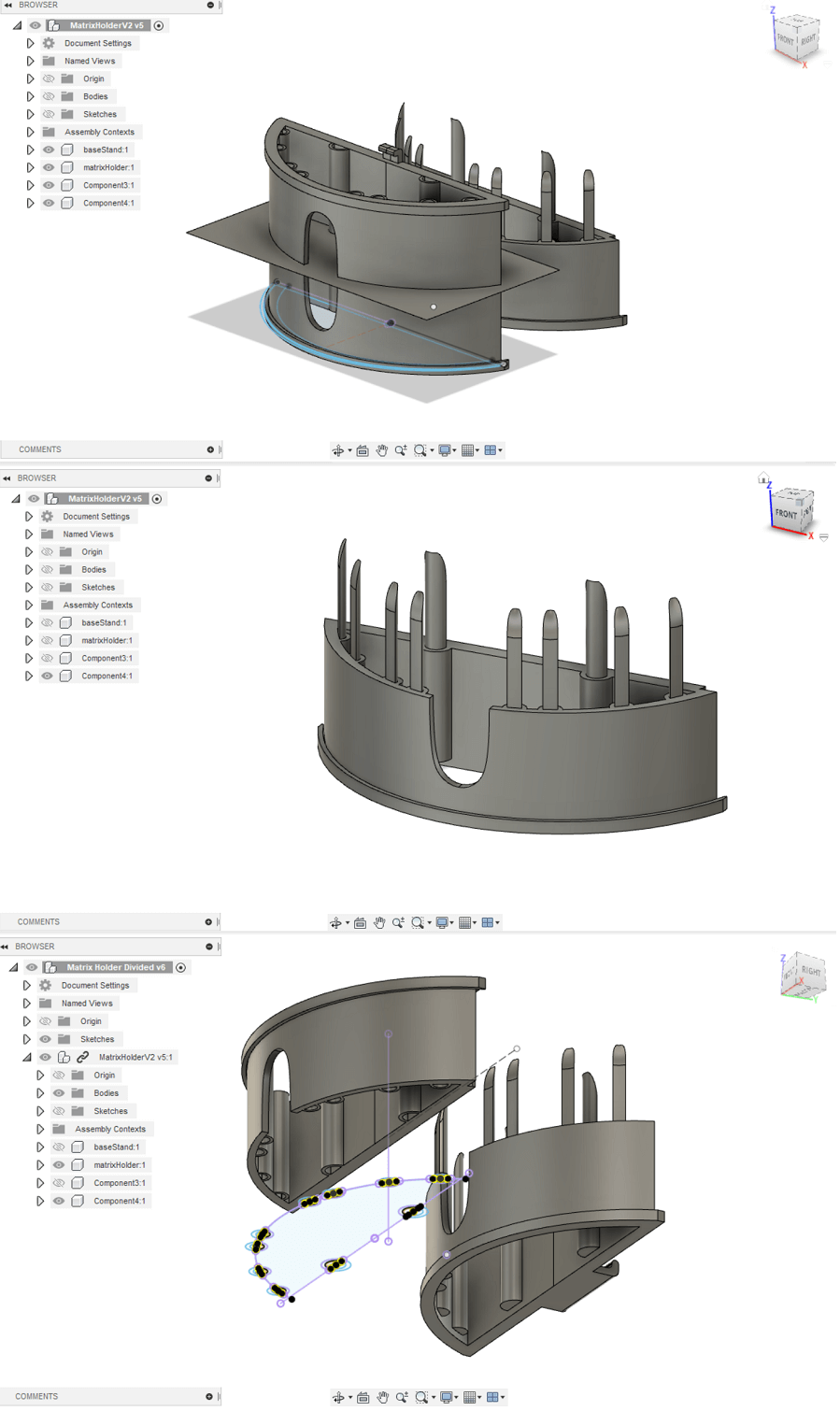
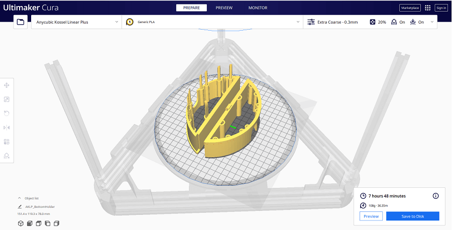
Once I checked the right tolerances, I start recreating the whole 3D model again. I made some improvements and I figured out the best way to let the LED matrix slide into my holder is to divide that in 2 parts, like is shown below:
Here a better view from the Slicer Cura of the whole piece divided in 2
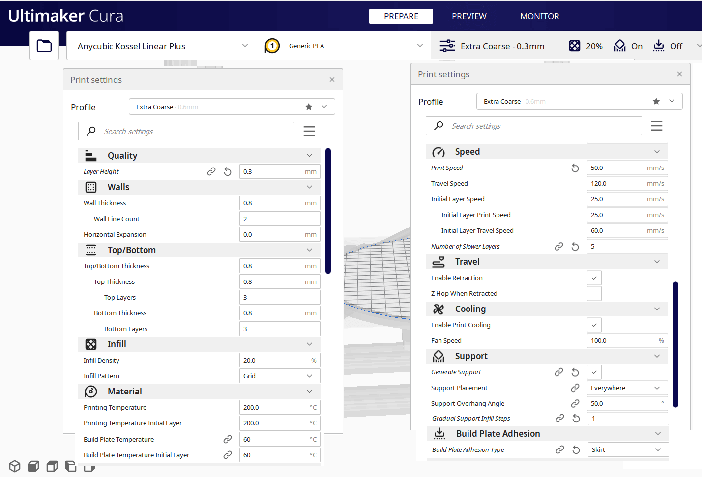
Here the paramenters I used in the Cura Slicer software:
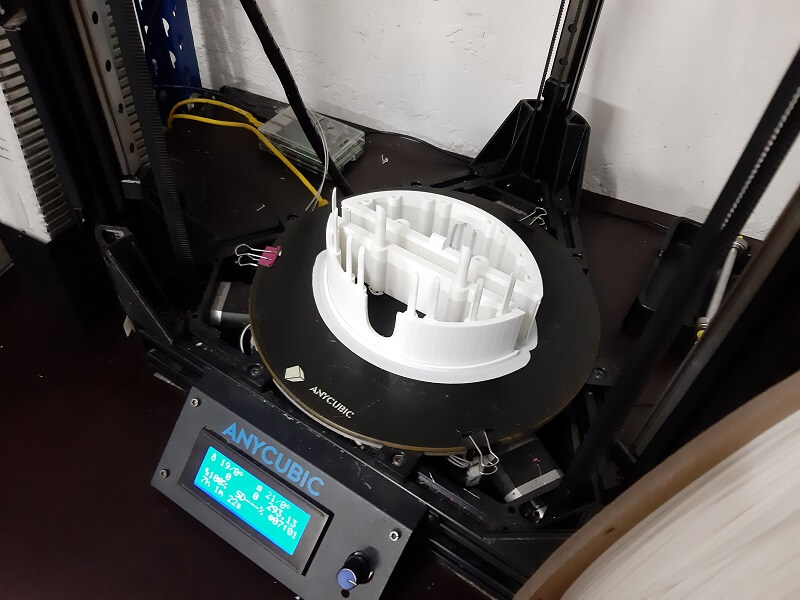
And here the 3D print:
Consideration: this model can not be easily made subtractively, First, for the pegs that serve to fit the two halves,
which are so long for a normal mill-bit and would require a CNC with extra dimention degree. Second, the hollowness is such that it would create too much waste to realize it subtractively.
Below you can see the final assembly with the LED Matrix and the VR glasses, I'm still not completely satisfied with the design and I'm going to improve it whenever I have more time to dedicate to it. Also the top hook (you can see it circled in the image below) that I need to anchor the matrix to the frame of the glasses wasn't 3D printed properly.
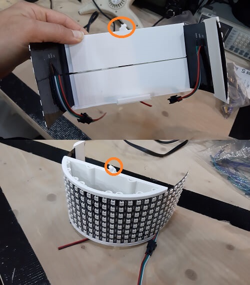
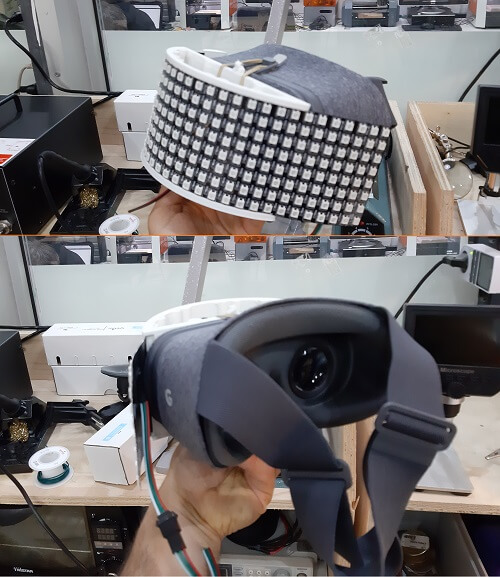
At the end I still managed to attach everything together, but still It could be way better.
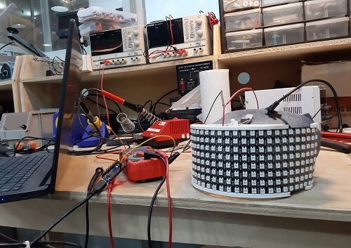
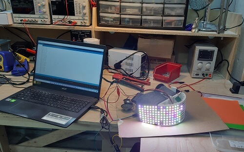
Below the pics of the first test using the LED matrix, to see how it goes on, jump to the assignment of week 8.
Warning: THIS PART IS NOT COMPLITED YET, I DIDN'T HAVE TIME TO FINISH IT, HOPE TO HAVE IT DONE IN JULY
To make the headset functional, you need to be able to see outside when you are wearing it. That's why I'm going to connect an IP Camera (pointing in front) to the smartphone that it will obviously be in the VR case.

This is the Camera Holder project:
Which will be attached to the LED Matrix Holder through the specific slots designed previously.
Copyright © 2018 - All Rights Reserved - Domain Name
Template by OS Templates