Useful Links
comments week 6
- Link1 ✔
other comment
What a coincidence, the day before the start of this week I got the cnc I bought on Aliexpress a few weeks before. It never happened that a product arrived so fast.
VIDEO UNPACKING
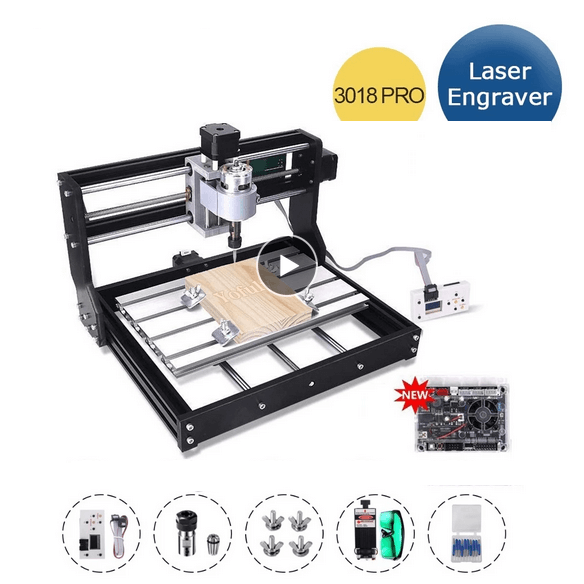
The model I bought is CNC 3018 Pro with Laser Module of 15W
Unfortunately I haven't had time to build everything up yet, I hope to have more time in the next weeks... but something tells me that it won't be that easy (Considering I am writing this page on the 17th of June and I didn't mounted the machine yet).
-----THEORY CNC ---------- 2.5 size innercut / outerCUt different mill-bit
The project I drew inspiration from was a book that my classmate Ximena showed me.
The book is called Nomadic Forniture 2 and it's about how to build sustainable fornitures for tiny spaces.
Browsing the various models, I was interested by the following chair, in terms of beauty and simplicity.
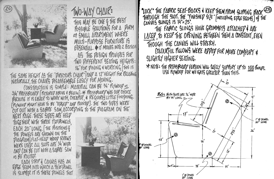
The model is called 2-Way Chair, a chair that can be flipped to became a couch...and so I had my own inspiration.
I first proceeded to create the sketch on Fusion 360, but inspirated by the flippible design I wanted to add some personal changes.
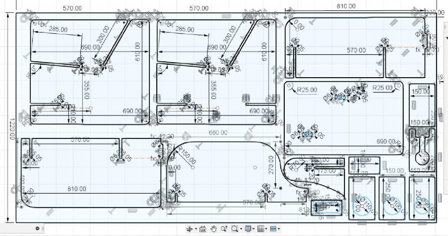
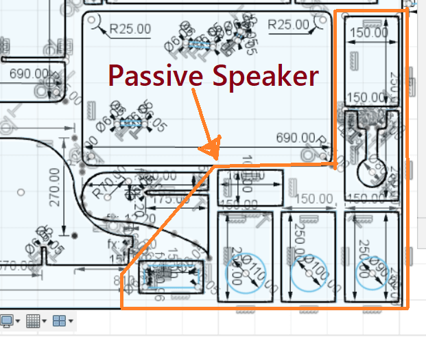
As you can see, while Nesting the whole design, I had some room to put another small design so I decided to realize a Passive Speaker as a Side CNC project.
I want to point out that the design above is just the final version after several attempts:
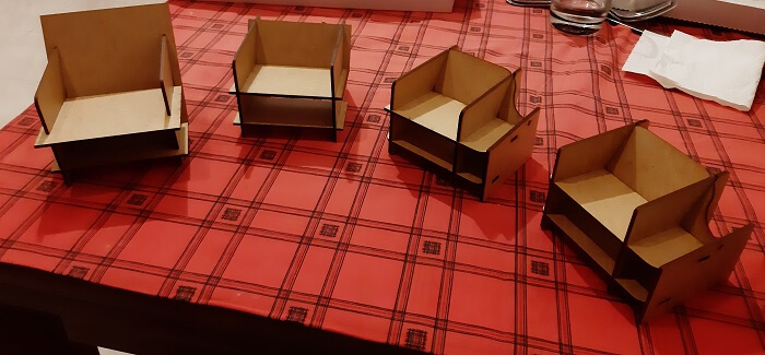
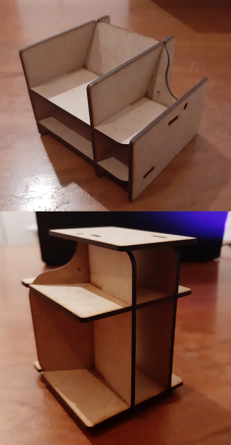
The model ultimately resulted in a small Couch/chair that when flipped can be used as a shelf.
I called it Storauch, as a fusion of the words Storage and Couch.

Here you can see the 2 orientation of the model, the first is a couch and the second a shelf.
Before I mentioned the term NESTING, meaning insert the parts of the design inside the size of the wood table I'm going to use.
In my case the chosen wood board has the following dimensions: 2440 x 1220 x 12 mm
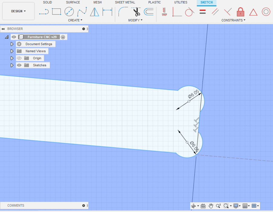
I then proceed to create the bones, among the 3 possible types. I excluded T-bones because they would be too visible, and also the Dog-bones because of the thickness of the table is too small compared to the diameter of the bit-mill (which is 6 mm).
The only one left is therefore the MickyMouse Bones which I then proceeded to insert:
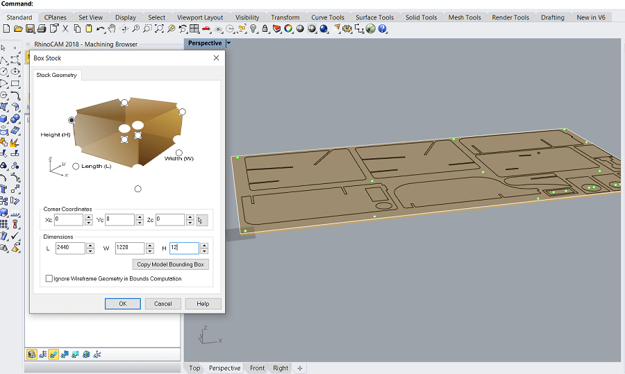
In order to prepare the file for the milling I used RhinoCam software.
Here we have the explanation of all the steps to get the G-code for the machine:
1) set the origin of the machine considering the dimention of the wood board that is going to be milled ( 1220 x 2440 x 12 mm in my case).
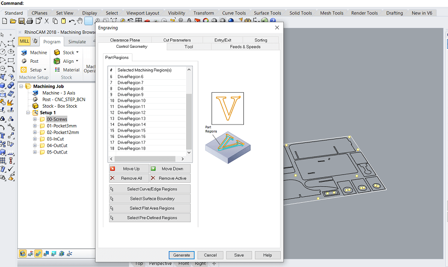
2) Set the Engraving for the Screws regions.
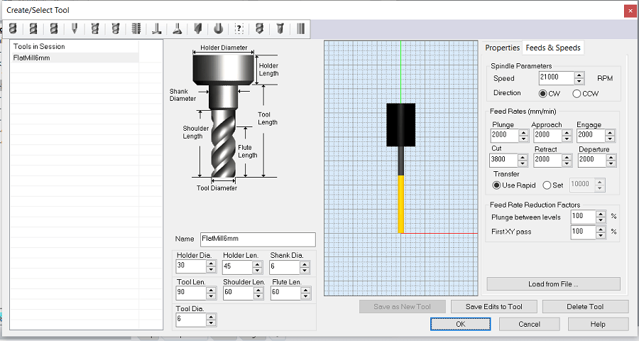
3) Creating the specific tool for milling: (important paramenter to remember 6mm of diameter, 60mm of lenght and 21000 RPM)
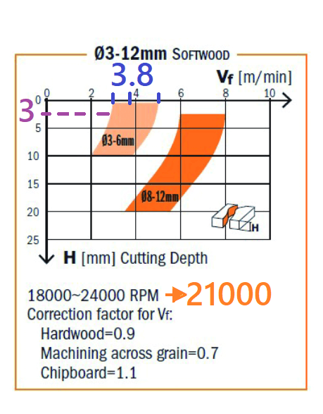
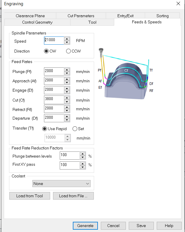
4) How to calculate the Feed Rate? Using the datasheet graph from the manufacter of the mill-bit.
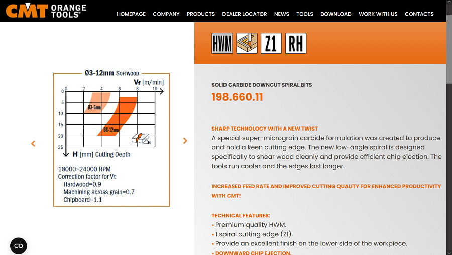
The graph shows how set the Feed Rate from the tool diameter, the Cutting Depth and the RPM. In our case the tool diameter is 3mm meaning we will consider the light orange curve, the cutting depth is set to 3mm, so depending on RPM value we could have a feed rate range from around 3m/min (if RPM is choosen to be 18000) to around 5 m/min (if instead RPM is choosen to be 24000). Considering the machine I am going to use has an RPM of 21000 the feed rate value I am going to use would be more or less in the middle of the range, around 3,8 m/min.
5) Here it is set the feed rate when the bit is approaching or leaving the board, it is recommended to set an lower value than the one calculated before for the cut (2000 mm/min in this case).
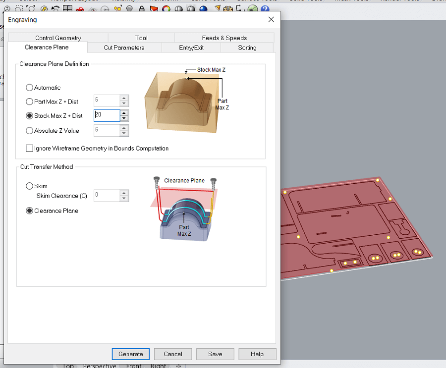
6) Clearence paramenter, same as the Job Hight in the mini-CNC machine when we mill PCB.
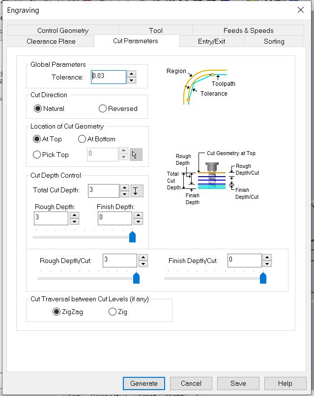
7) Setting of the Tolerance (lower is the value, closer would be the cut to the profile of the curve of my design. I.e. with a value of 0 the cut would follow the exactly the curve profile of the design) and Cut depth control, here we decided the depth of the Rough and Finishing Cut.
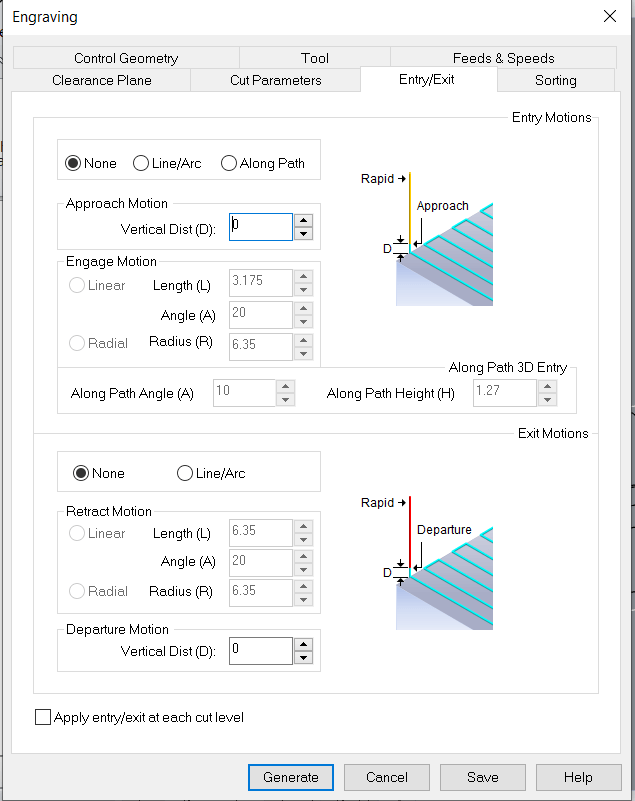
8) Setting how the mill-bit should enter and exit the material, considering we are engraving holes for the screws there is no need to set up this paramenter.
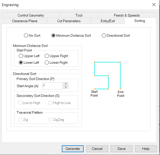
9) Sorting, meaning deciding the order of the hole engraving.
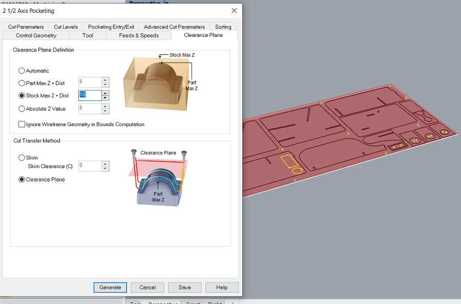
10) Setting the Clearance for the Pockets
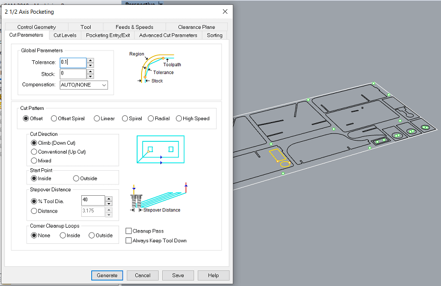
11) Setting the Tolerance and the StepOver Distance for the Pockets. The Step Over distance is the percentage of the mill-bit diameter that cut the material in each cicle, so a 100% Step Over means the whole mill-bit will cut the material in each cicle.
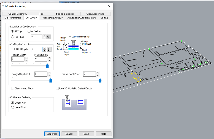
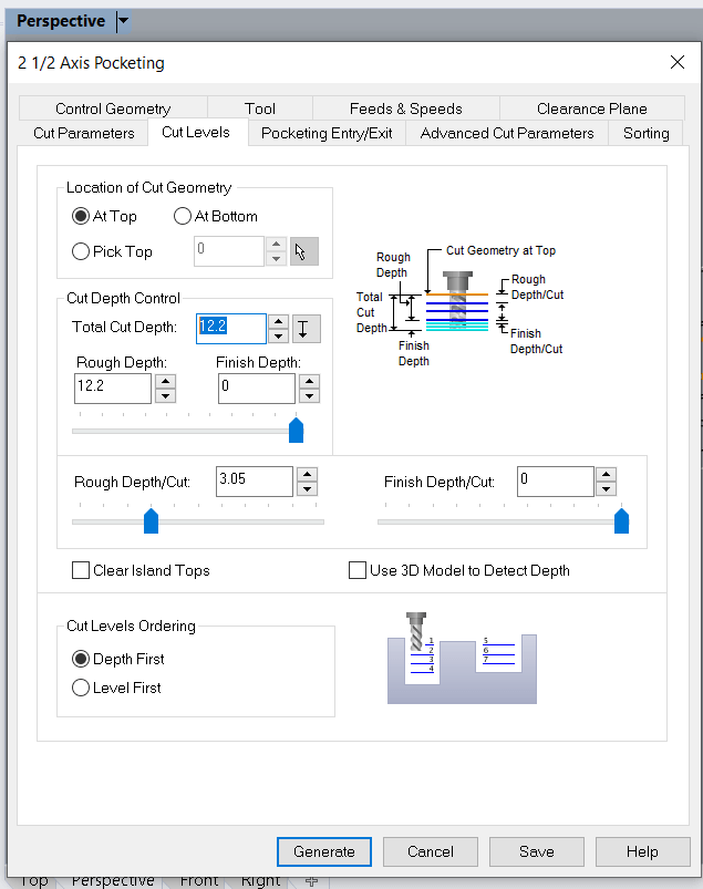
12) Changing the Total Cut Depth to 3mm because that will be the deepness of the Pockets.
13) Changing again the Total Cut Depth to the maximum (12.2mm) for another Pocket profiles, I could have also opted for choosing an inner cut set up but, considering the narrow of the profile, in this way I avoid small residues of material left in the center of the profile that could have flown away.
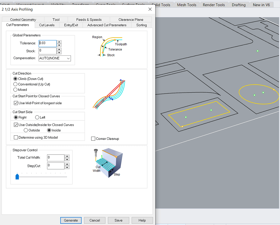
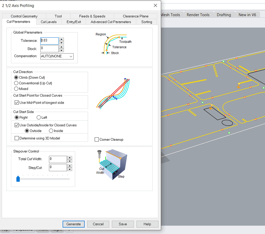
14) Cutting of the Inner Profile as we choose in the following parameter together with the Climb Cut direction.
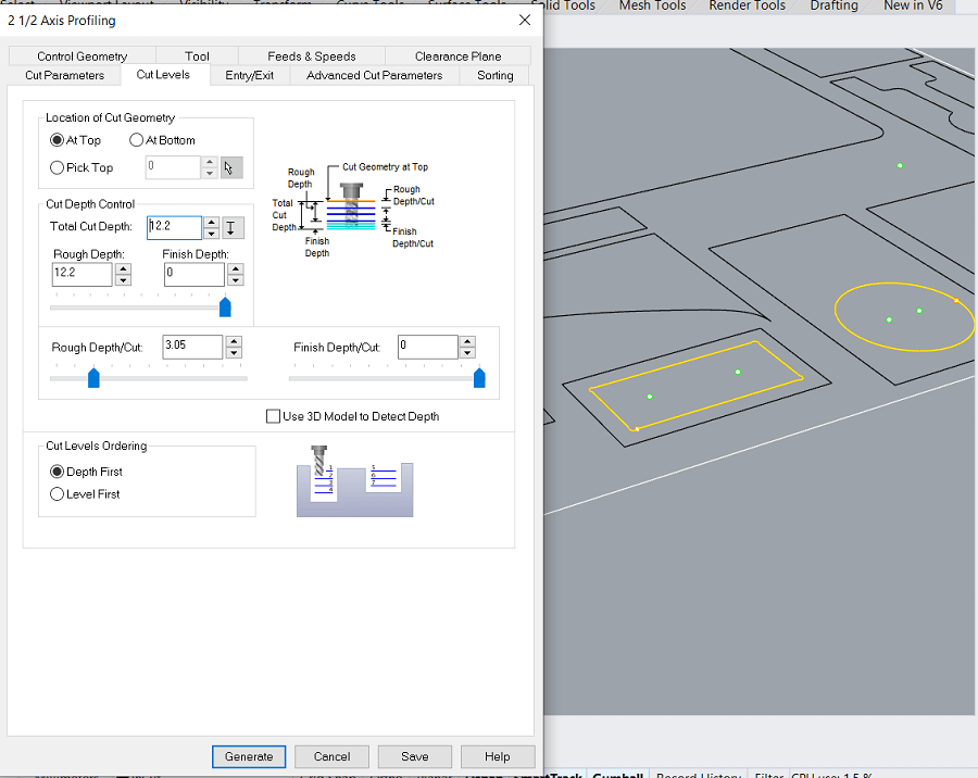
15) Setting the total deapht cut, the maximum 12.2 mm.
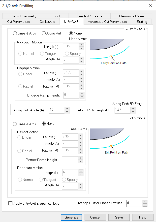
16) No gradual approaches in Entry/Exit parameters considering I am cutting a soft material as wood.
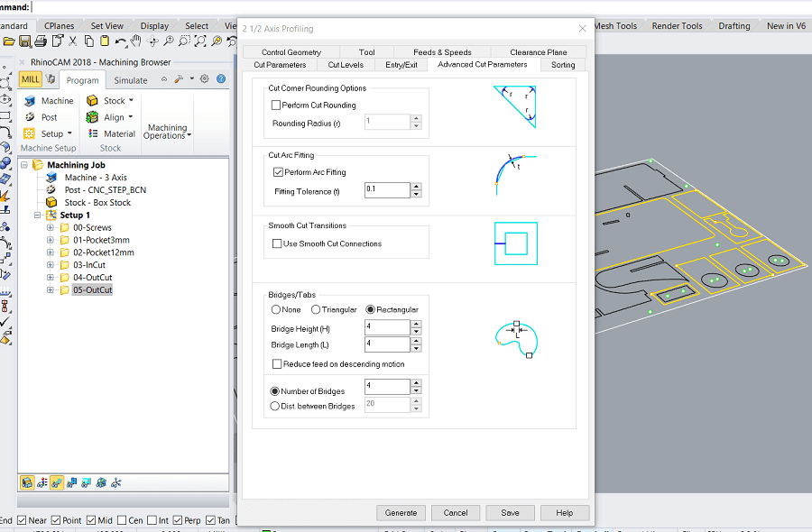
17) In Advanced Cut Parameters, bridge dimentions are set (2mm of high x 3mm of lenght in our case).
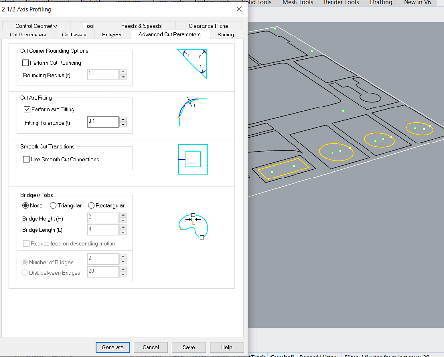
18) Setting the OuterCut for some of the profiles.
19) Setting the Bridge dimentions for the Outer Profiles.
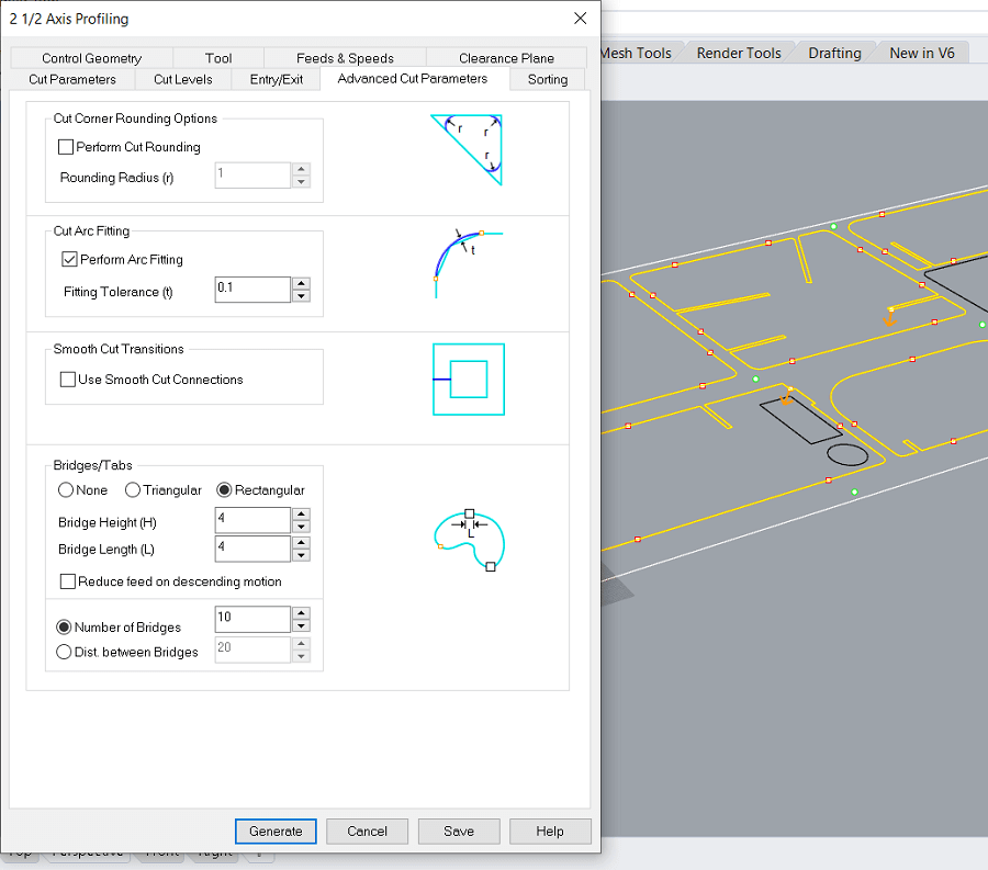
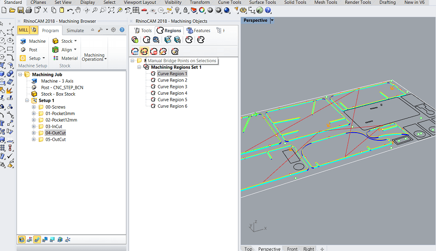
20) Manual setting of the position of bridges in Outer profiles where the default placing of the bridges done by the software was not satisfing, because most of them were placed on the curve reducing the quality of the cut.
21) Setting the Bridge dimentions for the rest of the Outer Profiles.
To mill my design I am gonna use the Raptor X-SL.
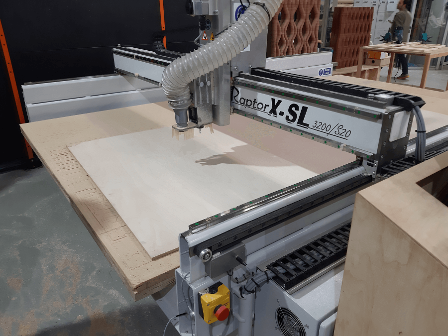
We are gonna then use a DownsideCut Mill-Bit of 6mm
Setting the XY origin:
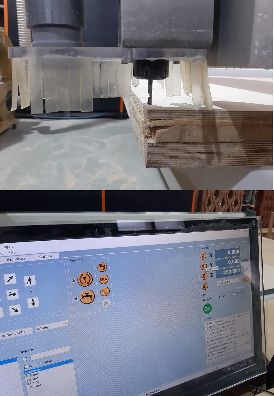
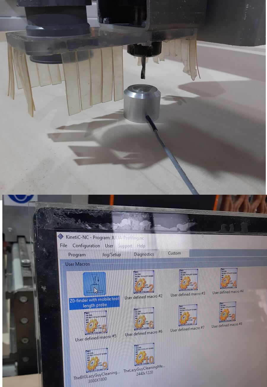
Setting the Z origin with ther proper push-botton function:
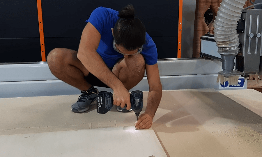
Before launching the Project we need to set the screws, the CNC machine will help doing it creating proper holes where insert the screws in.
I want to point out the importance to not insert the screw direcly into the wood table, but let it out once before inserting it completely. This is needed to avoid the separation from the cutting table and the sacrifice board while screwing.
Me, screwing all the holes:
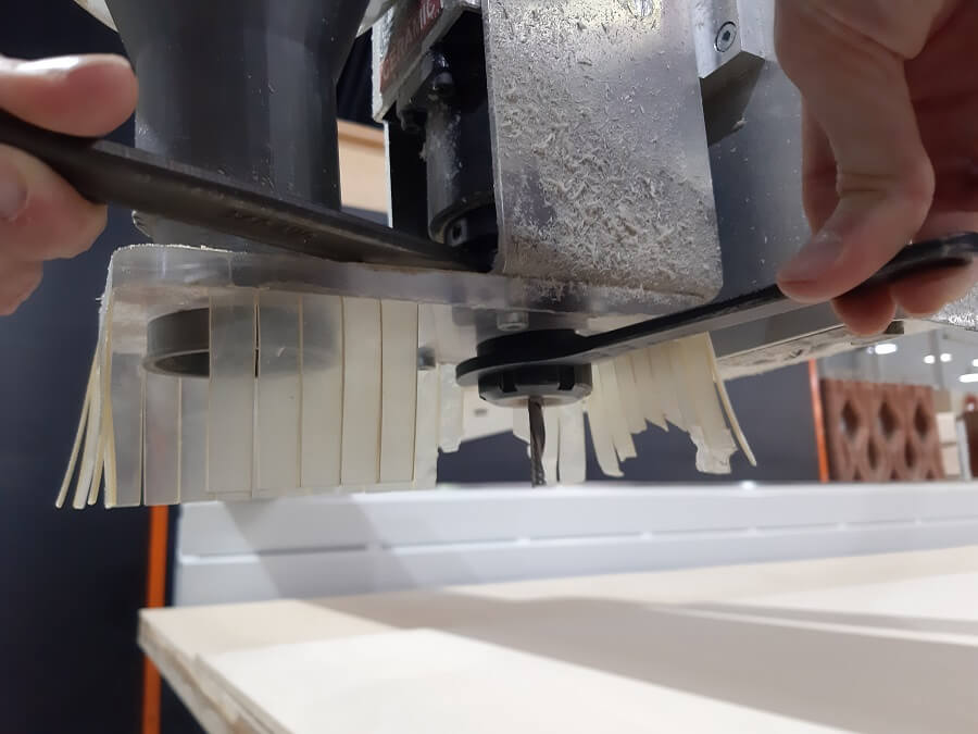
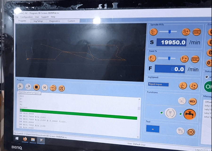
Once the preliminary operations are done, we can start the milling:
This is the finale result:
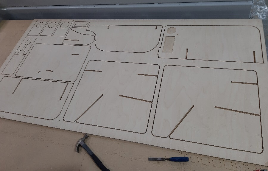
Before taking the pieces out, you need to remove the bridges
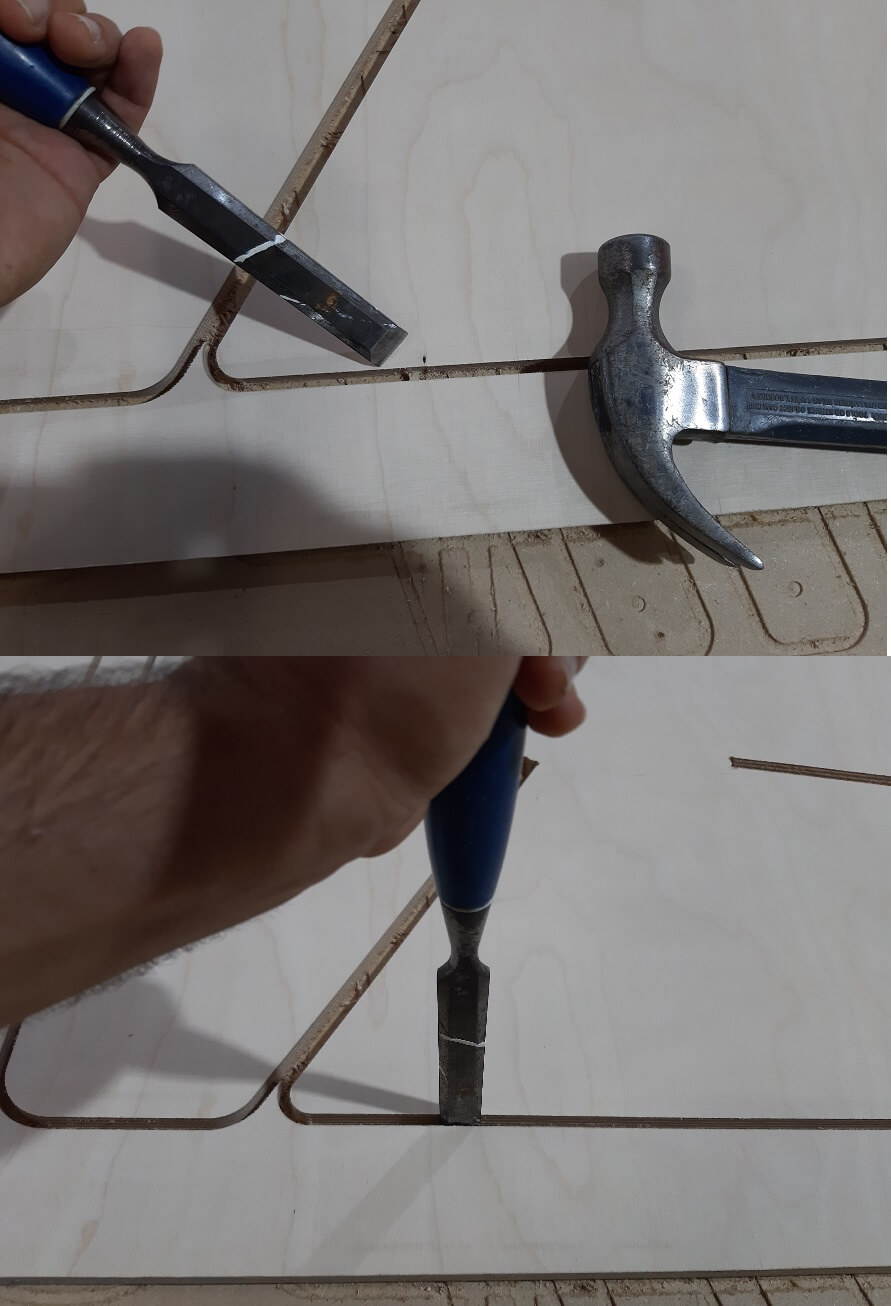
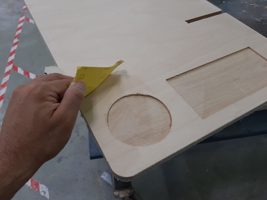
Obviously the milling process is not ideal, you will likely need to sand the pieces after:
I am gonna mount all the project after I will bring the pieces to my place in Italy, so forgive me if there is no pic of the project completed. In exchange here you can see the Passive Speaker working:
Copyright © 2018 - All Rights Reserved - Domain Name
Template by OS Templates