Embedded programming is a specific type of programming that supports the creation of consumer
facing or business facing devices that don't operate on traditional operating systems the way
that full-scale laptop computers and mobile devices do.
Hence Embedded programming is the creation of computer software designed and developed to control
embedded devices or an embedded system that we can define as a purpose-built computing platform that is designed to
accomplish a specific software-controlled task, such the microcontrollers we are using here in the FabLab for our assignments.
I am aready familiar with embedded programming, especially through the Arduino IDE.
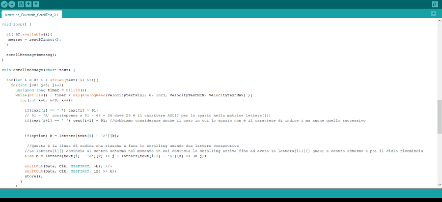
Below you can see a snapshot of a code I created for controlling a 8x8 Matrix LED to let it display scrolling-text
with out any external library aid.
Part of the quite long code of my device
To see the device, click here to access the video in the Output Device Page.
Testing my Own Samduino
As I explained in week 6, I made an electronic board
using the SAMD11C with various pins out that I could program as I want. Basically my own version of the SAMDUINO.
I then made a second board consisting of a button and a potentiometer, which
act as a Digital and Analog input module for the SAMDUINO, the digital input is made by the button
and the analog one is the potentiometer.
Problems with the Module board
There were two problems with the input module, the first regarded
the pin Out of the SAMDUINO, I mistakenly believed that all pins could be used
as digital and analog input, I then discovered is not the case as it is described in the
SAMD11C datasheet.
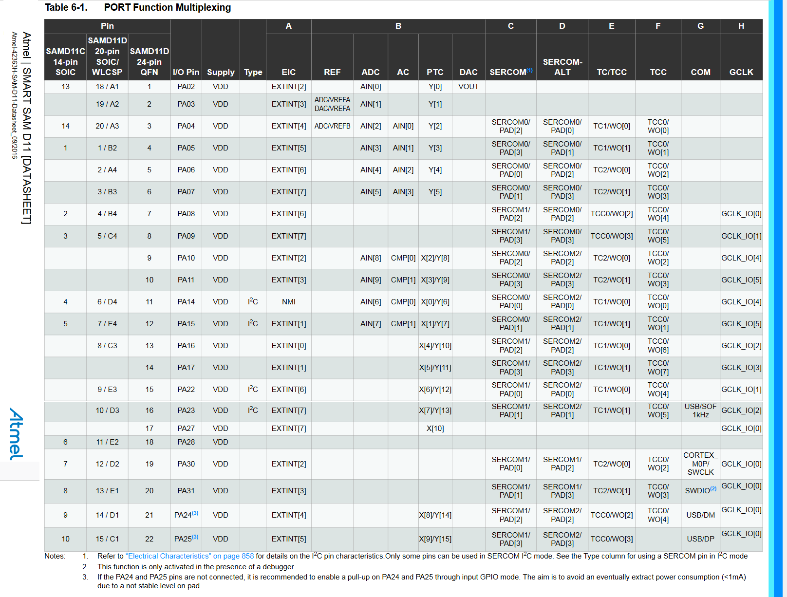
Specifically, in the page 13 and 14 of the datasheet you can find a table where is described the functions of each pins:
Datasheet Table in page 13/14
So if I want to know which pins are suitable for Analog input, I consider the first column (regarding the type of microcontroller I am using: SAMD11C), the 9th column
regarding which pins is connected to Analog Digital Converter and in the end the fourth column where is shown the number you use to call that specific pin in the Arduino IDE.
This is a summary table:
SAMD11CAnalogPin
SAMD11C datasheet number
SAMD11C pin number in the IDE
ADC pin number
13
2
A0
14
4
A2
1
5
A3
2
8
A0
3
9
A2
4
14
A9
5
15
A7
6
28
no
7
30
no
8
31
no
9
24
no
10
25
no
The same is confirmed in the SAMDUINO website, as shown below:
Samduino Website and Input/Analog Pins
This way I could not directly attach the module to SAMDUINO as in the elegant way as I preventivated but I had to use additional ugly cables.
Expectation VS Reality
The second problem was far more serious from the theoretical perspective. It was about the HW debouncing
I designed that turned out to be wrong, to my shame.
On the Debouncing Hardware Design section I explained how a capacitor was needed
to prevent sensing the mechanical bouncing that occurs inside the button while you release it.
The problem was every time I connected the input module to the SAMDUINO and pressed the button,
the latter would inevitally reset itself. Basically a short circuit occurred.
Where did this short circuit come from? From the capacitor itself.
How is that possible?! A capacitor should act as a open circuit in constant voltage regime.
That's very true, but that happens in steady state circuit, in my case it was not. Because the voltage
across the capacitor change rapidally from 0V to the maximum when the button is pressed.
Hard to belive for a electronic beginner, but when there is a rapid change in voltage across the
capacitor, it acts as a short circuit.
The impedence of a Capacitor is inversely proportional to the frequency of the Voltage across it
So every time I pressed the button, the capacitor saw a rapid change voltage going to short-circuit the 3.3V directly to the Ground.
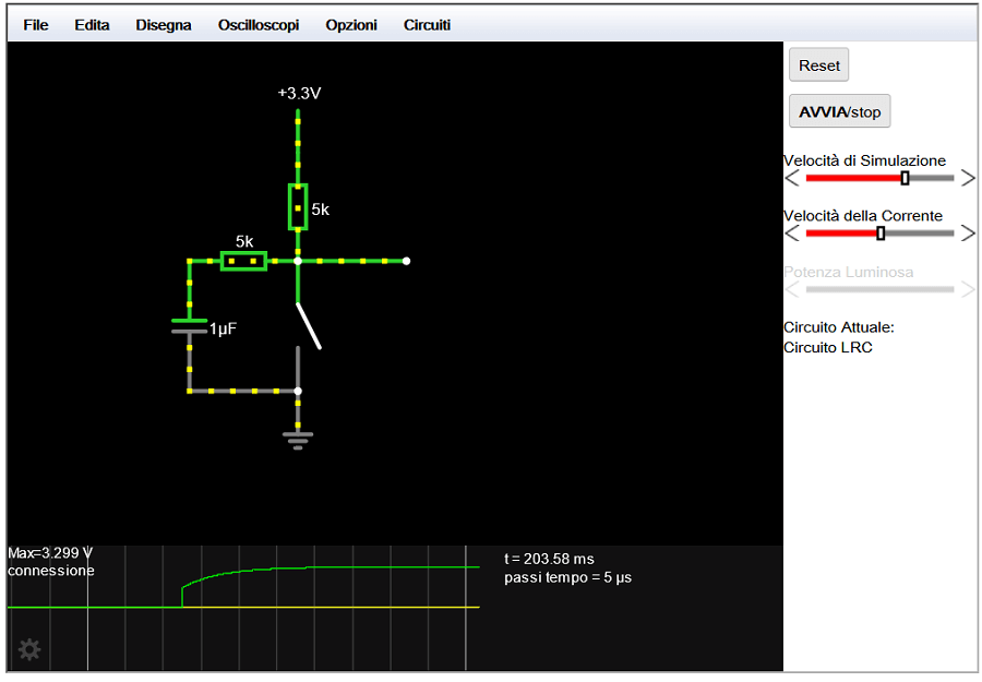
To solve the problem I would have had to redesign the whole board with a system of HW debouncing of this type:
New HW debounce design
What I did however was simply unsolder the capacitor to no longer have malfunctions.
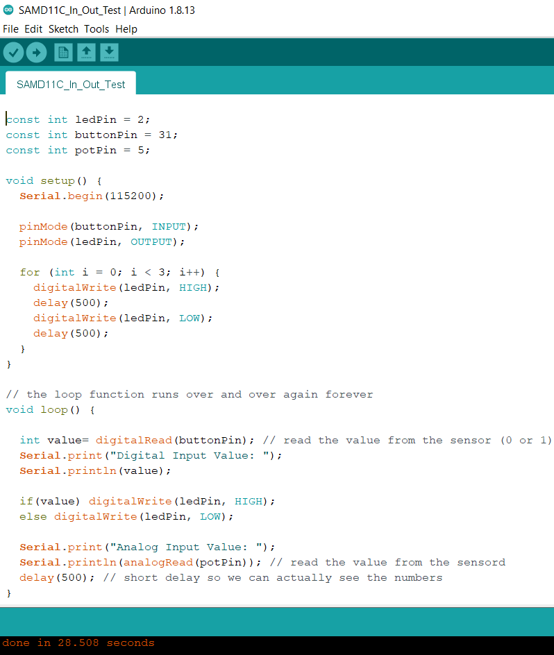
Input Module Testing
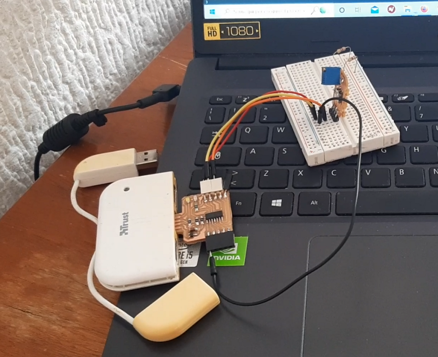
Once I could use the input module without further problems, I proceeded to the button test to turn on the LED. Here the schematic:
Push-button test
And here there is the code running:
Digital and Analog input Code
Basically whenever I push the button, the Samduino will light up the LED and will display 0 on the Serial Monitor (1 when the button is released), changing the Potentiomenter
will also be displayed in the Serial Monitor.
How it works
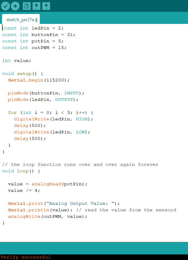
I then test the potentiometer (again as an Analog Input) to change the duty cycle of a PWM signal
The schematic, including the Scope
This is the code:
PWM generator Code
How it works
These tests were not problematic as I am already widely familiar with these concepts.
Warning: The following part it is not completed yet. I am writing the minimum to get
      the assignment approved and in July I would be available to finish it.
Programming of the LED Matrix
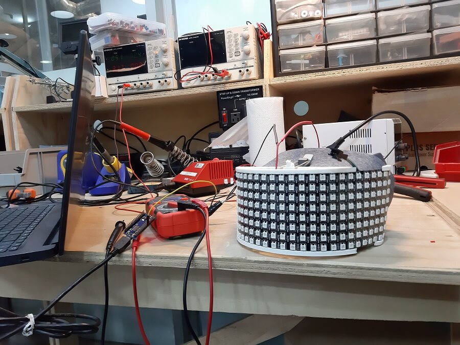
In Week 5 regarding 3D printing I created a support for a LED matrix Visor.
Now, it is time to make it work.
The Led Matrix with the 3d Printed holder
The Matrix I am about to program is a ù32x8 LED Matrix with a total of 256 WS2811 CHIPSET.
I managed to create custom animations on the Matrix in 2 ways, as presented below:
I METHOD: Led Matrix Control Application (Ver 1.3.2)
I took inspiration from this youtube video from a famous youtuber: GreatScott:
GreatScott Video
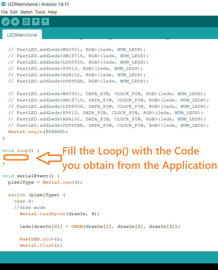
It basically showed an application, you download a file where you find a pre-made code for the Arduino with the loop
function left in blank to be filled later using the application itself.
LED Matrix Control default code
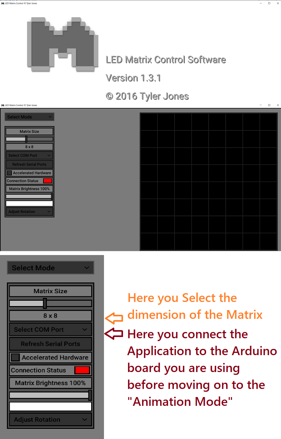
This is how the application is presented, in order to control it you need to connect the arduino first, and then select the size of the
Matrix you are programming.
The Application
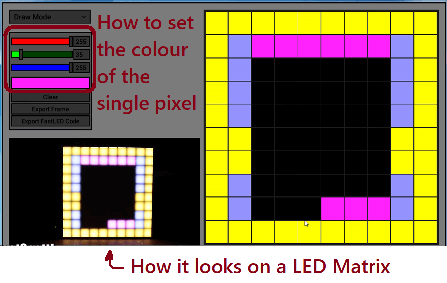
Once the connection is enstablished, you can start playing with the pixel colour as it's shown:
Changing the colour of the pixels
Finally you can export the code and fill the loop() function in the previous code to obtain the drawing you created with the application
Obtaining the instructions to put in the previous arduino code
PROBLEM: The application works only for squared Matrix while mine is Rectangular, but
you can see it as 4 squared Matrix of 8x8, so in order to display 4 different letters I need to repeat each time the procedure.
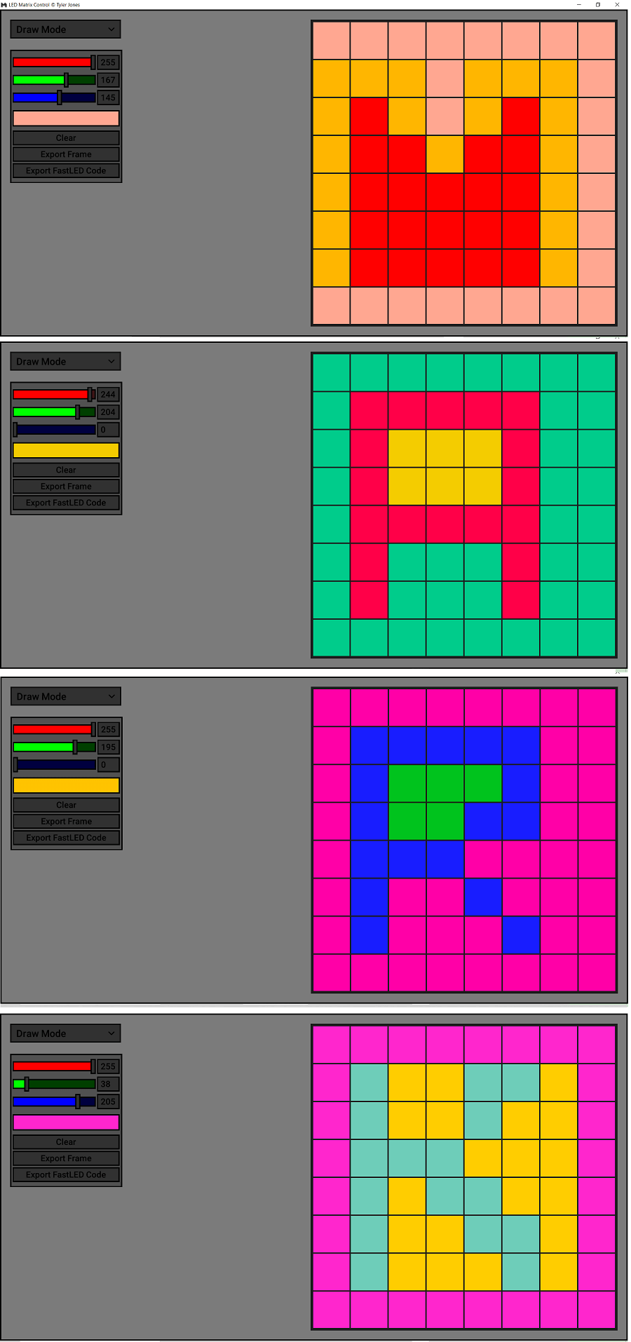
Defining the letters I want to display
The problem will remain because whenever I export the code it will consider only a Matrix of 8x8, so an array index starting from 0 to 63, while
I need an array starting from 0 to 255 accordly to the dimension of my Matrix.
Specifically, I need the array starting from 0 to 63 for the first letter, the from 64 to 127 for the second, from 128 to 191 for the third and finally
from 192 to 255 for the last letter.
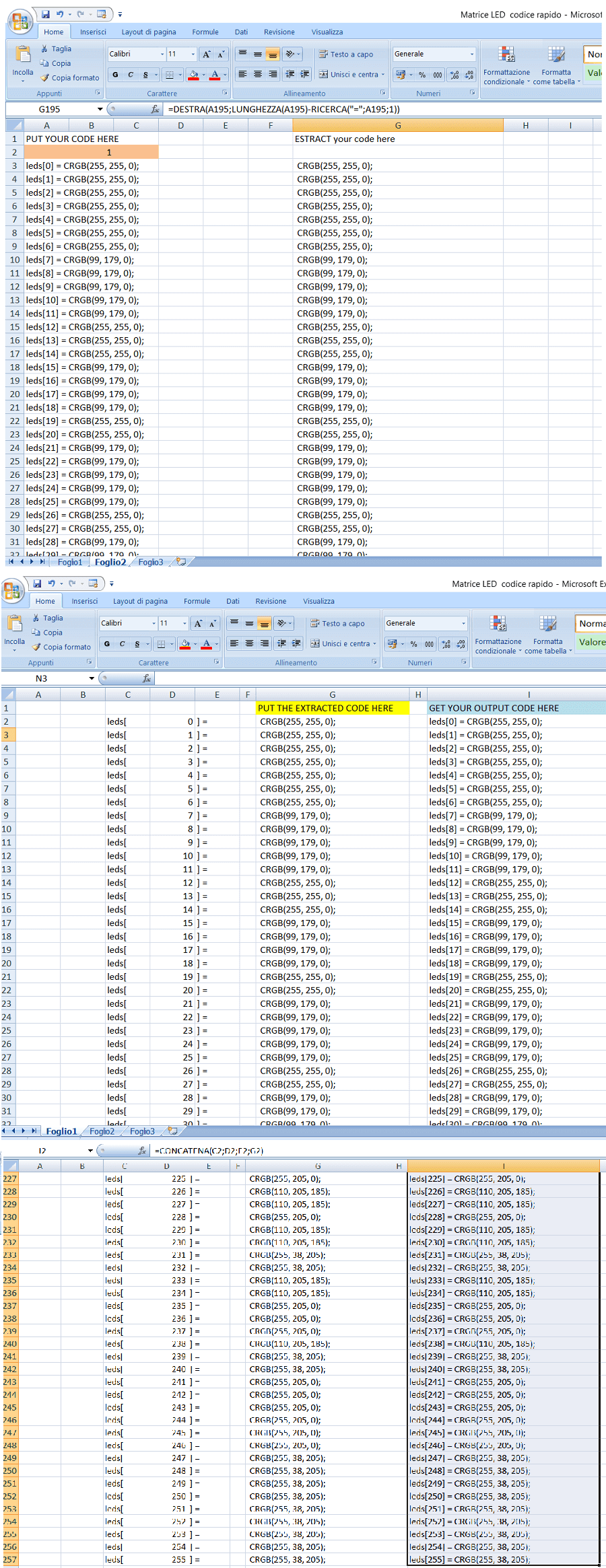
In order to accomplish this I used an Excel sheet where I just paste the esported code, extracting the Colour Info and then inserting it again in the Array for my Matrix:
Using a Excel sheet to adapt the code to my Matrix
This is the final result:
Displaying MARK
II METHOD: FastLED XY Map Generator Web-Application
A totally different method to control the Matrix involved a FastLED library example code.
It was shown in this Youtube Video where the owner managed to control a Customized LED Matrix that contained even holes!
How control a random type of LED Matrix
To do so, you use a Web Application where you can obtain the code after setting the parameters of your matrix.
Web App
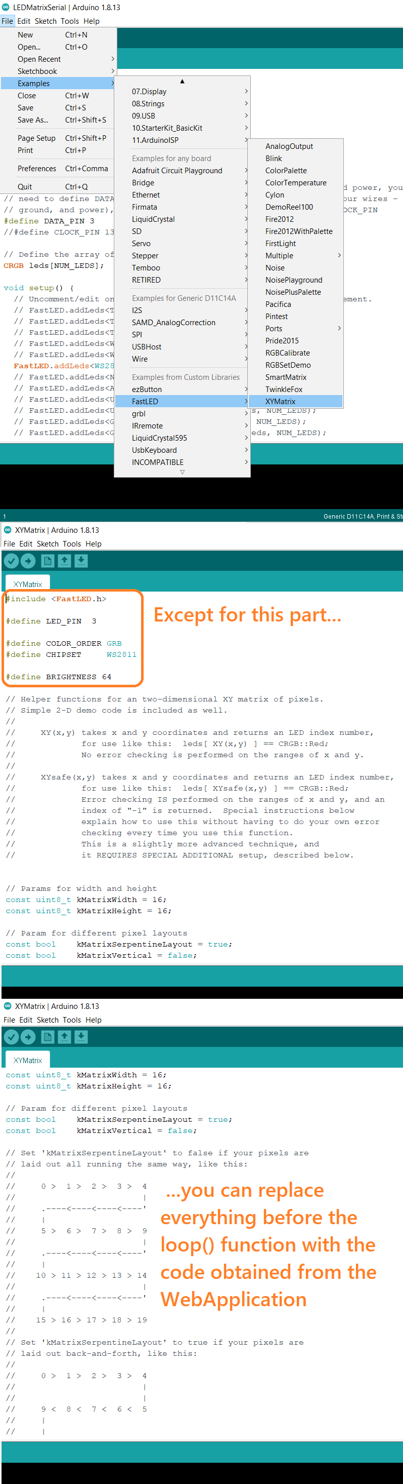
After that, you just open the XYMatrix code you find in the FastLED sample folder and paste the code in there.
Changing the XYMatrix Code
And here you have waves of rainbow ;)
Rainbow Animation
This week I tried to programming the LED matrix with the aid of an Arduino Nano. (OLD TYPE)
LED matrix description
strange behavior (not GND connection) with test code
define the sense of the matrix by flashing one LED at a time
Use of the application for creating graphics
Use of a second application for creating a rainbow type of animation on led matrices
of any kind and size.
Future projects VU meter.