Electronics Production
group assignment:
- characterize the design rules for your in-house PCB production process
Workflow to produce electronic circuits
Cheatsheet
Context: You already have the design of the board you’d like to use, and you are happy with it (no design changes required).
This assumes that the designs have been customized for the machine that you will be using: e.g. Since the machine will use a 1/64th inch milling bit, the traces will need to be at least 1/64th inch separated from each other, etc..
If this is not the case, you might have to customize your board design. Check out our documentation from Week 06 Electronics Design.
Creating the milling programs
- Load the design into mods and load the custom program for the Roland SRM-20 that you can
find in the Barcelona Lab.
- You can find the customized programs for milling and cutting in Edu’s documentation
- You will use the milling program to mill the traces, and the cutting program to cut out the outline of your board.
- Load the custom program into mods by:
- Right-clicking on an empty space, and choosing “Programs > Open program from file”
- Load the milling program you downloaded
- This program has been customized for the Barcelona Lab machines, so you don’t have to customize any other settings.
- If you cannot use this custom program, you will have to customize the settings manually. See custom settings section for a detailed breakdown.
- Load the traces file that has the design of your board (PNG or SVG)
- Click “Calculate” and the *.RML file will be downloaded
- You will use this file to mill your traces when you are on the Roland machine
- Repeat the process with the cutting programme, and the outline file
- This will give you the RML file to do the outline.
- Load the custom program into mods by:
Launching the milling programs
- Book time in the Roland SRM-20 machine.
- lol. no one ever does it!
- Go to the computer lab, and launch the V-Panel for SRM-20 app. This application is used to send milling jobs to the Roland SRM-20 machine.
- Get a new blank board.
- Stick it to the bed with double-sided tape.
- Make sure you cover the entire surface to avoid it moving out of place.
- Load the 1/64th inch. milling bit (for tracing) into the machine
- Remember to hold it in place with your finger while you tighten it, to make sure it doesn’t fall off and break while you are tightening it.
- Configure the 0,0 for X and Y axis
- Close the safety cover
- Use the VPanel app to move the milling bit to the starting coordinates for X and Y only.
- Click on the “X/Y” button under the “Set origin point” in order to configure those to 0,0
- Configure the 0 for the Z axis
- ⚠️This is the dangerous (expensive) step, if you do it wrong/carelessly
- You need to move the milling bit close to the board, without it touching.
- You will need to carefully unscrew the bit and lower it gently by hand until it rests on top of the board.
- Once it is resting on top of the board, tighten it again, while still holding it in place to avoid it going up/down.
- Click on the “Z” button under the “Set origin point”
- Validate your settings (Optional)
- You can lift the spindle up a few mm
- Turn on the spindle. Wait until it reaches 10k rpm.
- Lower it very slowly until it reaches Z = 0 and see if it’s touching the board and milling a tiny dot into it.
- If it’s not milling properly, you Z is set too high, and you should readjust.
- You have successfully calibrated your equipment. 👯♂️👯♀️🎉
- You are not ready to load the RML file into the application.
- Click the “Cut” button.
- Delete any pending tasks that might be on the list.
- Click on “Add” to load your file
- ⚠ Mill the job!
- Click on Output to launch the milling job
- Other tips:
- You can always pause the job to check out what it looks like, and resume later.
- You can cancel the job to fully stop the operation. This will not let you resume and you will have to restart the job from the beginning.
Launching the cutting programs
Repeat the steps above, but load the 1/32 inch. into the spindle instead of the 1/64 inch one ⚠️IMPORTANT: You will need to recalibrate the Z axis only!
Manually Configuring Settings
Milling settings
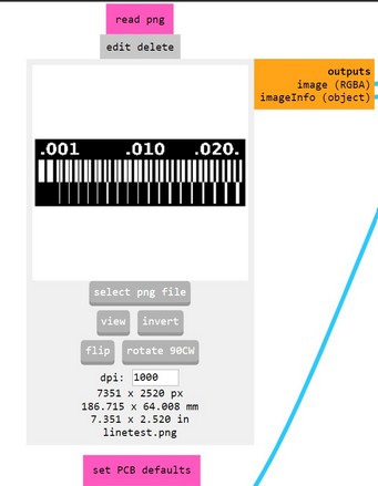
- Make sure that your file has a DPI of 1000
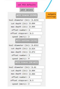
- Under PCB Defaults module;
- Set offset number to 4
- Set speed to 3mm/s
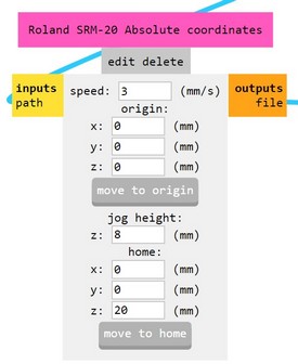
- Under Roland SRM-20 Absolute Coordinate module:
- Set speed to 3mm/s
- Origin to 0,0,0
- Jog height to 10mm
- Set Z coordinate for home to 20mm
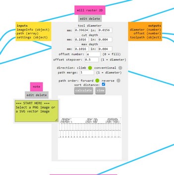
- Under the mill-raster 2D module:
- Check if the offset number is 4
- Check that direction is set to Climb
- Connect a line between the Absolute Coordinates module (the output node) to the “Save File” module.
- Click on Calculate and the RML will automatically be downloaded by your browser
Cutting settings
Cutting the outline uses the same settings except for these small tweaks
- Under PCB Defaults module;
- Set offset number to 1
- Set speed to 1.5mm/s
- Under Mill Raster 2D module:
- Set Max depth: set 1.75mm
Our lab equipment
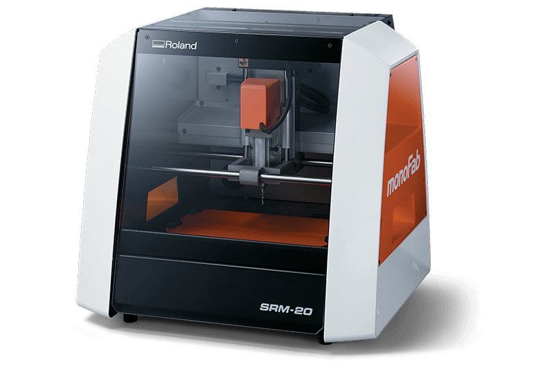
Roland SRM-20
Our barcelona lab has a couple Roland SRM-20 milling machines.
Testing our machine tolerances
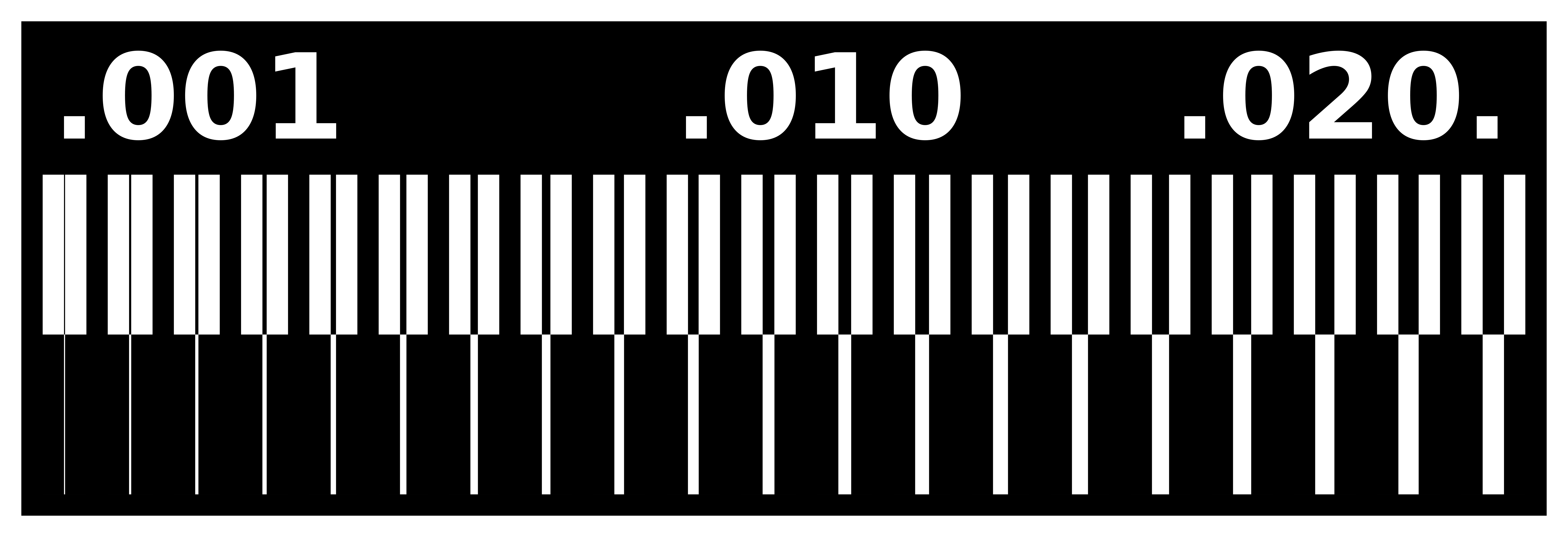
During week 3, we had to test and find out what are the tolerances for our equipment, so we could make important design decisions when milling and designing new boards.
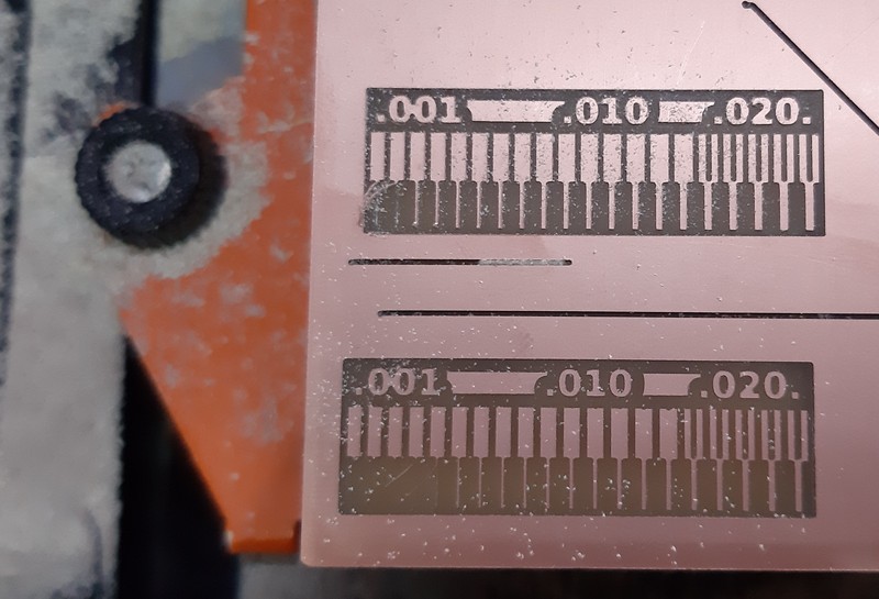
To find out, we printed out a test board and this is the result.
Conclusions:
Physical Constraints: When cutting from the outside, anything under 0.007mm will be scraped off and will not have any copper material left.
Mods Logic: When cutting from the inside, anything under 0.014mm will not be cut, as the milling bit is too wide, and Mods will not allow it to get milled.