Week 6 Electronics Design - Group Assignment
The purpose of this week’s group assignment is to become familiar with the test equipment in our lab. Josep told us that we have a pocket oscilloscope and a voltmeter.
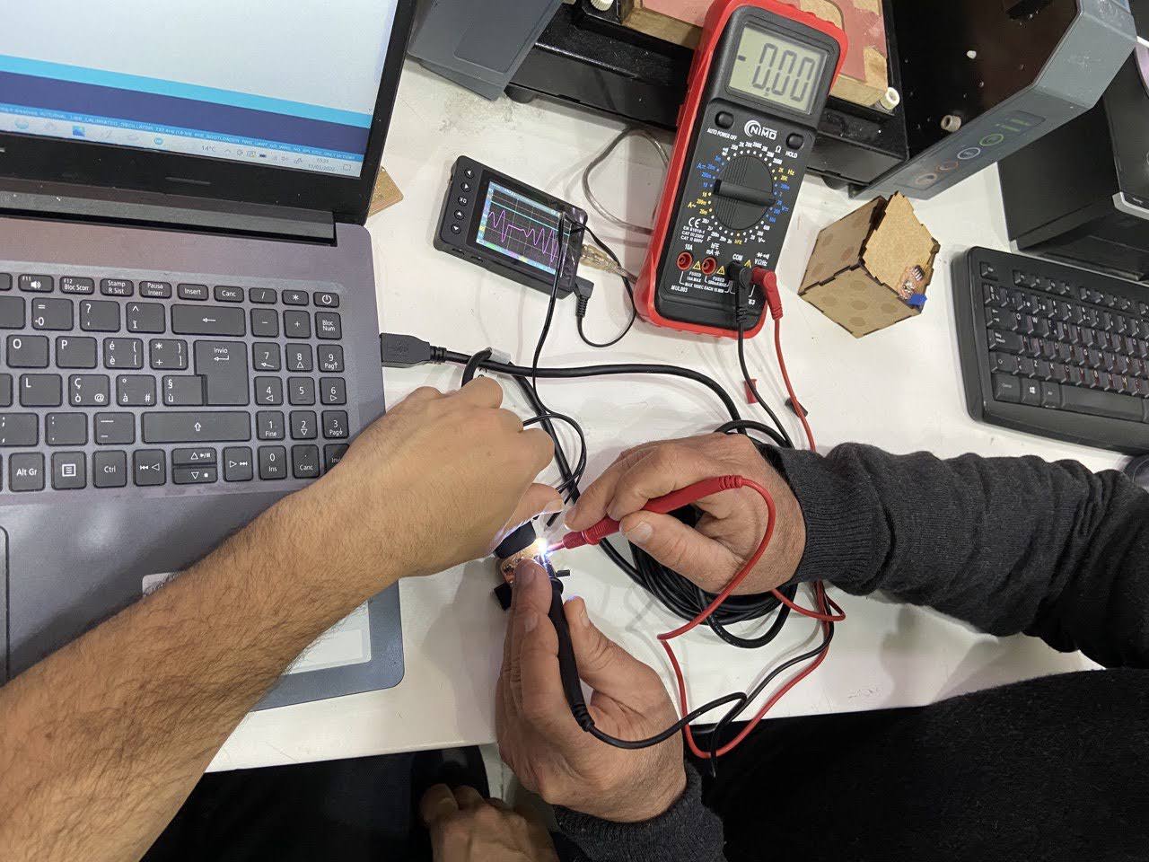
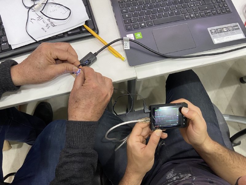
We used the digital volt meter (DVM) and pocket oscilloscope to read some some voltages on the SMD11c board that Marco built. We changed the blink rate on the LED by editing the sketch in the Arduino IDE and observed the voltage across the LED.
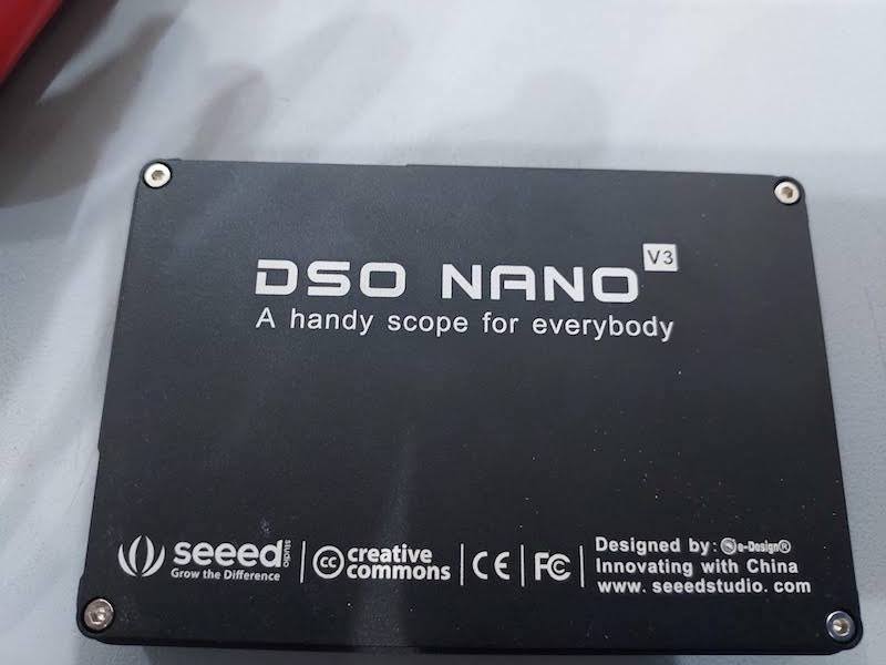
We used a pocket oscilloscope called DSO Nano v3, which was an open source project sold by SEEED. It is no longer manufactured or supported by the manufacturer, but there is a community that continues to make modifications to the product.
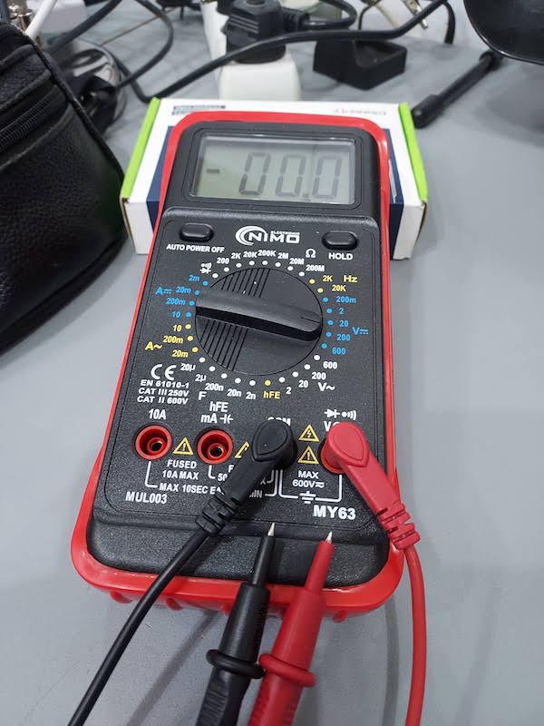
The digital volt meter (DVM) is a NIMO electronics MY63 MUL003 meter.
Digital Volt Meter
First we measured the voltage in and out of the regulator. We noticed that the 3.2 volts on the output of the regulator dipped when the LED came on.
The voltage into the regulator was a steady 5 volts.
Next we looked at the voltage across the LED and the LED and resistor. The program turned the LED on for one second and off for two seconds.
We calculated what the voltage should be across the resistor (Vdd-Vled=Vr) and then measured it to confirm. The voltage was within a few hundredths of a volt of what we calculated.
Pocket oscilloscope
Here are the specs on the scope:
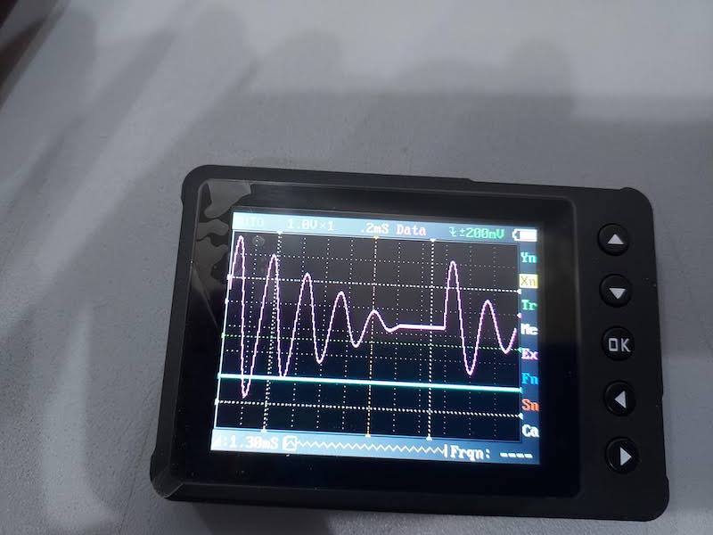
An oscilloscope allows you to see how an electrical signal changes over time. It shows a graph of the signal - the x axis of the graph is voltage and the y axis is time. You need to set appropriate voltage and time scales in order to see the voltage on the screen.
We used the pocket oscilloscope to observe the voltage across the LED as we changed the parameters of the light blinking Arduino IDE sketch. The key to being able to observe the trace on the oscilloscope is setting the voltage and time scales to the right values for the signal we want to observe. The pocket oscope can only go up to about 200 khz, plenty of bandwidth for what we were looking at.
One second on 2 seconds off
We varied the arduino sketch that turned the LED on and off, changing on and off times, making a kind of PWM signal. We observed the behavior of the diode and the signal on the scope.
Reflections and Conclusions
It seems like it would be pretty easy to short things out using the leads on the voltmeter and oscilloscope, although we didn’t. Checked the data sheet on the LM 3480 and it is short circuit protected. USB is also short circuit protected.
We didn’t try to measure currents because you need to break the circuit and insert the meter into the circuit. It is not easy to break into a pcb trace to measure current. This is one disadvantage with PCBs over proto boards. You could design PCB boards that would allow current measurements. We could build a board with jacks for pins to read current - shorted in normal use but routed through a voltmeter when you want to read current.
It was surprising to see the output voltage of the regulator dip when the LED came on. The LED is only a load of about 20 ma, and the regulator is rated at 100 ma. I wonder what the actual current draw of the SAMD11C is. From the data sheet, the SAMD11C has a minimum amp load of 8 microamps to about 1 ma when on.
The oscilloscope is a complex device with lots of options. We barely touched the surface of its features. It would take a lot more time to become proficient in its use.