Networking & Communications
- Design, build, and connect wired or wireless node(s) with network or bus addresses
- Send a message between two projects
This week I want to focus on my final project, because even if I had some fun the previous weeks I didn’t go any further. So I want to decide which MCU I will be using and how to connect everything.
Building the network
I will use an ESP32 to be the main board of the project: this way, I will be able to connect an interface later on. This main board will handle the interaction with the project, first with buttons, then with proximity sensor, and finally web interface.
It will send messages to another board via I2C protocol that will contain all functions necessary to control the WS2812B addressable LEDs. I plan to use a ATtiny 412 at first and work with the tinyNeopixel library. I initially wanted to use the FastLED library as it’s very versatile, but my previous tests and the work of previous Fab Academy students (like this one) changed my mind.
In a second spiral, it will also send messages simultaneously to a board dedicated to the sound system, with an associated SD card to store music. I plan to use an ATtiny 3216, but I will need to run some more tests.
graph LR
  A{ESP 32} --->|I2C| B{ATtiny 412};
  B -->|DATA| C[WS2812B];
  D[Interface] --> A;
  A --->|I2C| E{ATtiny 3216};
  E --> F[Speaker];
  G[SD card] --> E;
  C -->|DATA| H[WS2812B];
  H -->|DATA| ...;
Graphs on Mkdocs
I used Mermaid.js directly integrated in Mkdocs to add this diagram to my page.
markdown_extensions:
- pymdownx.superfences:
    custom_fences:
        - name: mermaid
        class: mermaid
        format: !!python/name:pymdownx.superfences.fence_code_format
``` mermaid
graph LR
A[Start] --> B{Error?};
B -->|Yes| C[Hmm...];
C --> D[Debug];
D --> B;
B ---->|No| E[Yay!];
```
graph LR
A[Start] --> B{Error?};
B -->|Yes| C[Hmm...];
C --> D[Debug];
D --> B;
B ---->|No| E[Yay!];
Design of the secondary board
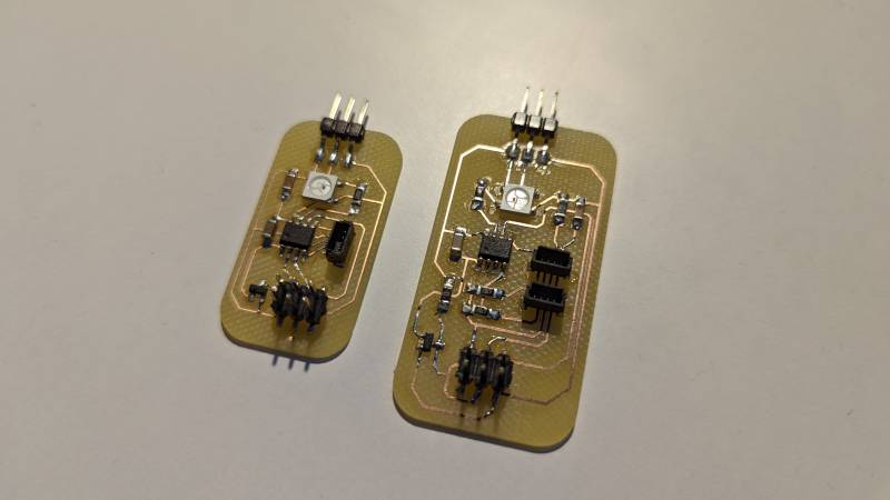
I started by designing the secondary board because it seemed that the proof of concept was lying there. I needed to expose the I2C ports and the serial ports because I wanted to test it properly. I also needed a port to control the RGB leds. The good thing about that is thanks to the hop-count protocol I only need one data pin for the leds.
KiCAD schematics
I decided to use a Qwiic connector for the I2C protocol: it’s very minimal in size and very popular amongst new components (Adafruit loves them particularly). I found the symbol and footprint for KiCAD on SnapEDA.

Later on this week, I realized I made several mistakes: I forgot to add the pull-up resistors for the I2C communication protocol. I redid the board, deleted the serial ports and added a Qwiic connector to add a bus for the I2C protocol.

Fabrication
I did the milling on the Roland SRM 20 as usual and it went well. These are quick boards to make and solder. What a pleasure to be able to prototype a board and realize it in the same day!
| First board | Second board | |
|---|---|---|
| Isolation | 5min | 10min |
| Non-copper cleaning | 20min | 25min |
| Cutout | 20s | 40s |
Programming and testing
To program the ATtiny 412, I need to use the UPDI I made earlier in the Fab Academy. I also discovered that the ATTiny 412 pinout is not straightforward: the pin PA3 I connected my leds to is not the Arduino 3, but the Arduino 4.
I also made some tests to know how many leds I could power without adding another power management. As it turned out, I cannot handle more than 25 leds with this board. It will be enough for the final project, bu it’s something to keep in mind for future reference. It’s also caused by the 3V3 regulator I used to keep consistency between the ESP32 data output and the ATtiny.
As I wrote before, I used the tinyNeoPixel library written by SpenceKonde to program the leds. The idea is to trigger some function thanks to the I2C protocol.
Test program for the ATtiny 412 using tinyNeoPixel library
#include <tinyNeoPixel.h>

#define PIN            4    // PA3
#define NUMPIXELS      25   // Careful to not go pass 25 pixels with the ATtiny 412

tinyNeoPixel pixels = tinyNeoPixel(NUMPIXELS, PIN, NEO_GRB + NEO_KHZ800);

void setup() {
    // Setup and clear all pixels
    pixels.begin();
    clearPixel();
}

void loop() {
    rainbow(10);
}

void lightPixel(int r, int g, int b) {
    pixels.fill(pixels.Color(r, g, b));
    pixels.show();
}

void clearPixel() {
    pixels.fill(pixels.Color(0,0,0));
    pixels.show();
}

void blinkPixel(int r, int g, int b) {
    lightPixel(r, g, b);
    delay(500);
    clearPixel();
    delay(500);
}

void rainbow(uint8_t wait) {
    uint16_t i, j;

    for (j = 0; j < 256 * 5; j++) { // 5 cycles of all colors on wheel
        for (i = 0; i < pixels.numPixels(); i++) {
        pixels.setPixelColor(i, Wheel(((i * 256 / pixels.numPixels()) + j) & 255));
        }
        pixels.show();
        delay(wait);
    }
}

uint32_t Wheel(byte WheelPos) {
    WheelPos = 255 - WheelPos;
    if (WheelPos < 85) {
        return pixels.Color(255 - WheelPos * 3, 0, WheelPos * 3);
    }
    if (WheelPos < 170) {
        WheelPos -= 85;
        return pixels.Color(0, WheelPos * 3, 255 - WheelPos * 3);
    }
    WheelPos -= 170;
    return pixels.Color(WheelPos * 3, 255 - WheelPos * 3, 0);
}
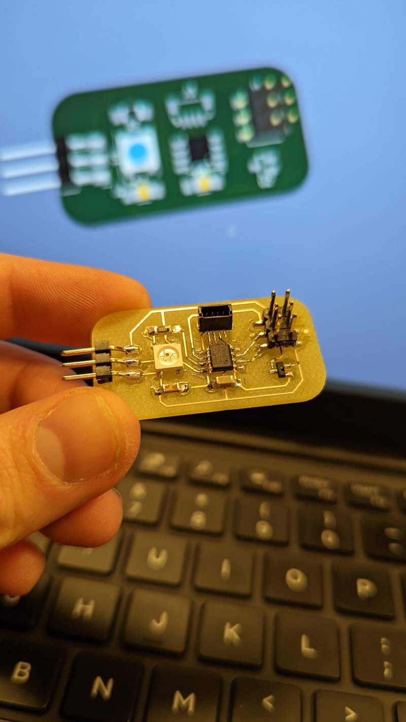
Design of the main board
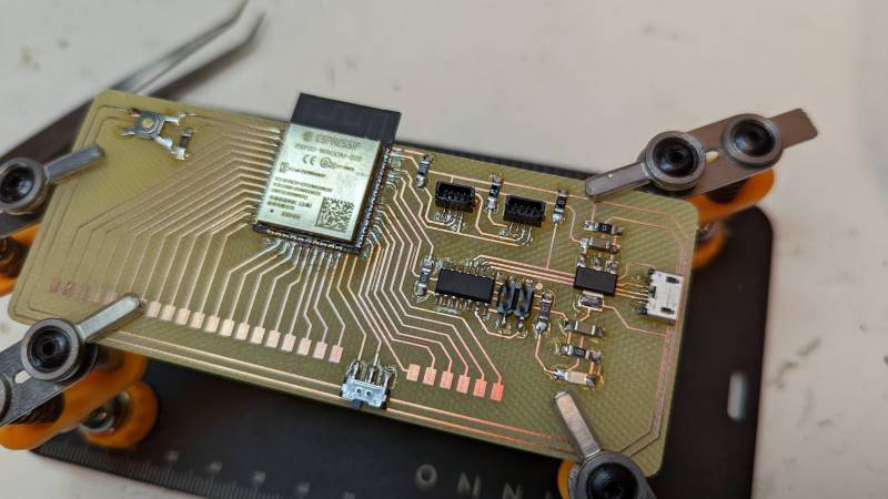
The secondary board being designed, I needed a brain! I never used an ESP32 before, so it was a challenge to read everything I could and design at the same time: I wanted to be done with the fabrication as early as possible to work on the networking part of the week. Oh my, was I naive again! I created a monster, as hard to design as to route and solder…
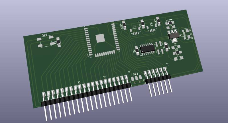
Schematics and PCB routing
First I looked into Neil’s ESP32 design board to understand the basics requirements for this kind of board. During Machine Week we used an ESP32, but it was an Adafruit Feather ready-to-use. Watching one of Neil’s video I noticed he needed to turn a commutator on and off before downloading a program and run it. I did some research and finally I found the Barduino project, which gave me enough information to launch myself in the design.
I also wanted to be able to program it through USB, so I added a SAMD11C connected directly to RX and TX. I wanted to try that for a long time, I hope it will work as intended!
Warning
When connecting RX and TX, be aware that the SAMD TX must be connected to the ESP32 RX, and RX to TX.

That wasn’t so bad, apart from the spaghetti-like breakout I had to make: I wanted to have access to more pins if needed. I also forgot the pull-up resistors for I2C in this one, but it was easier to redo the secondary board above than this one after I realized it. The routing was hard, especially becasue the Qwiic were hard to route. I could have done it differently but I only see it now. The next time will be better! It’s what I love about designing so many boards, it’s rewarding to notice how wrong you were and correct this in the next one.
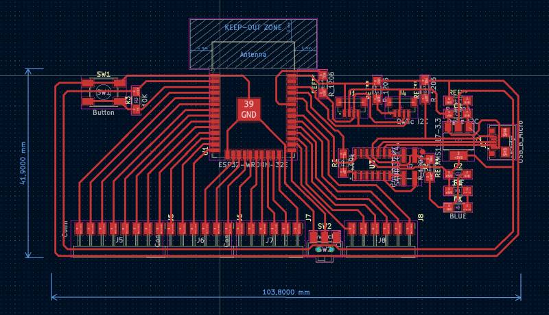
It’s clearly not the best-looking board I made, but it was Friday afternoon and I wanted to mill it before the week-end, so I stick with it.
Birth of a monster
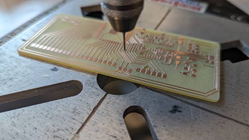
The milling went well, except for one weird moment before the non-copper cleaning operation when the milling happened in the air. I think I miscalibrated the Z axis. I redid the Z and everything returned to normal. It took forever to mill, but yet again I couldn’t have done without the NCC operation: I’m too afraid of shorts now, so I prefer loosing time during fabrication and be sure that my soldering skills won’t be too much of a problem later.
| ESP32 | |
|---|---|
| Isolation | 45min |
| Non-copper cleaning | 65min |
| Cutout | 2min |
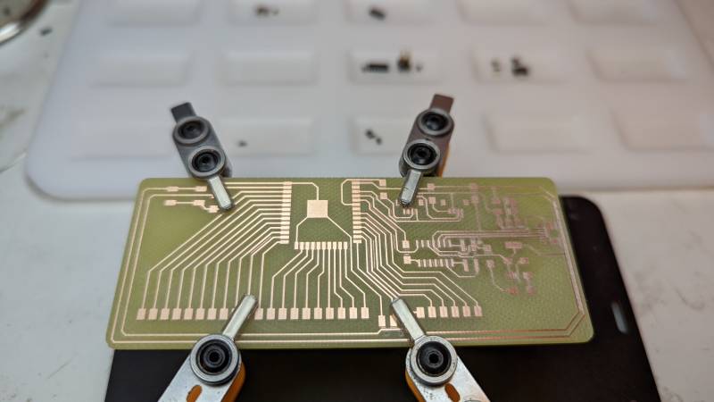
After milling I checked for shorts and didn’t find any, so I prepared the components to solder them in Monday morning.
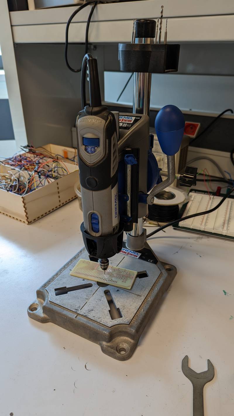
First thing Stephane told me on Monday when he saw my board was: “Have you forgot to drill the holes for the commutator?” …Indeed. I drilled them with the Dremel and a 0.8mm flat endmill.
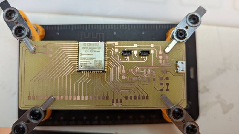
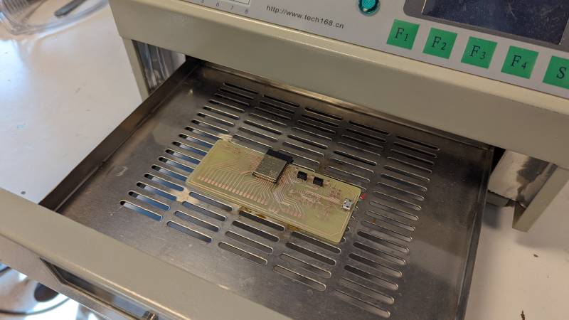
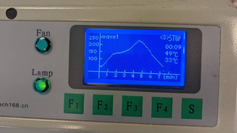
I then tried to solder the ESP32 with the hot air gun but I was too afraid to burn it (I know it’s stupid, but the components seem so fragile). Stephane suggested to use the oven and I liked the idea of soldering the trickiest components this way. So I placed the Qwiic connectors, the USB ports and the ESP32 carefully with solder paste and put them in the oven with the same program I used in Electronic Production week.
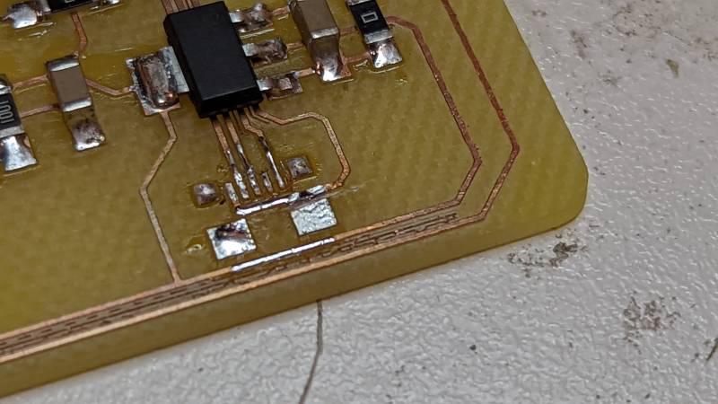
After that I soldered the other components easily enough. But when I firt plugged the board in my USB port the power led did not light up, and my mouse who was plugged in the same usb hub stopped working: I understood it must be a short, but it took me a while to figure out what was the cause of that. Finally I understood that the USB port caused that because the 5V track was touching the fixing pad underneath: another bad design, I was angry at myself for not thinking of that. Last time I used this USB port it was the ground underneath, and it didn’t cause any problem. But the 5V is another story. So I used the hot air gun to remove the USB port, I cut the connection between the fixing pad and the 5V track that I haven’t notice before and resolder the usb port.
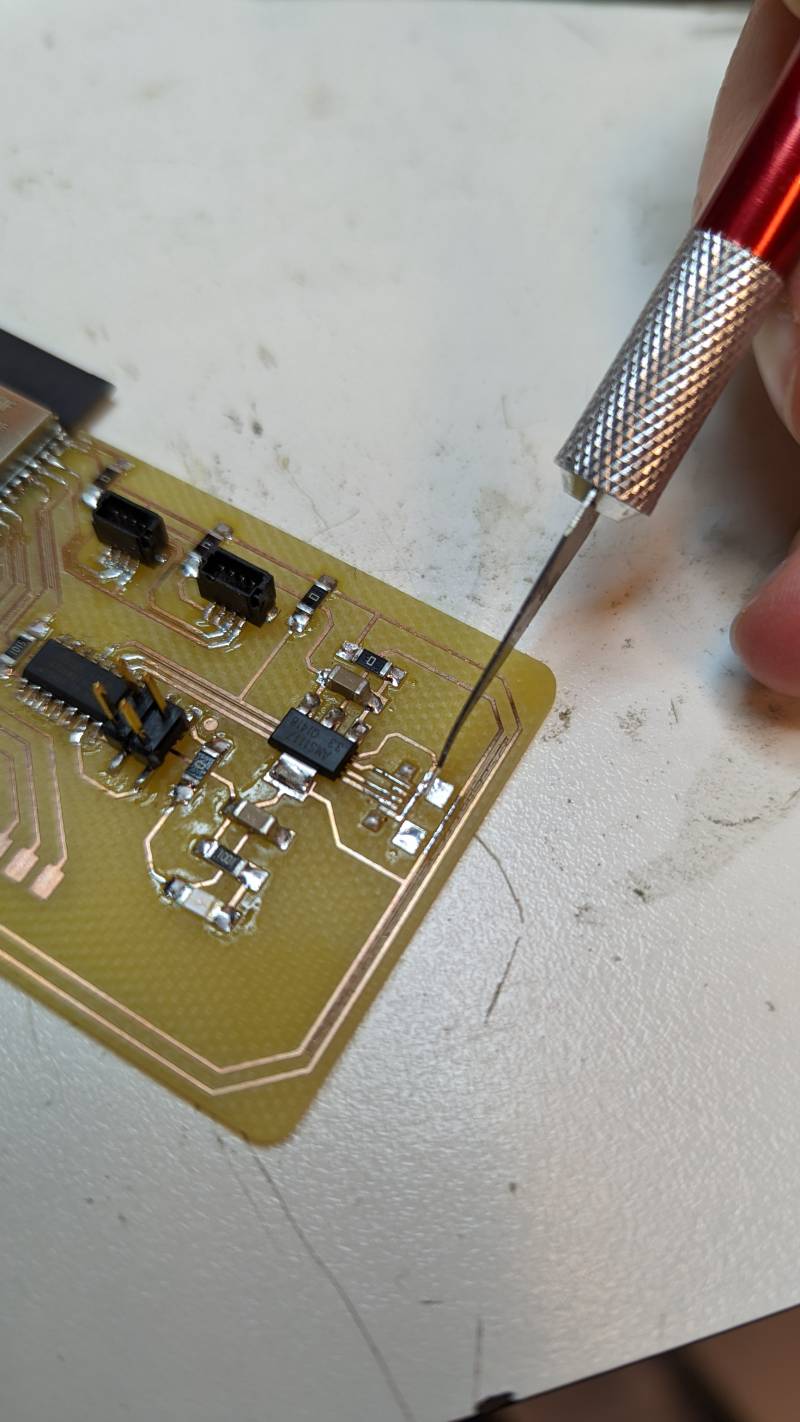
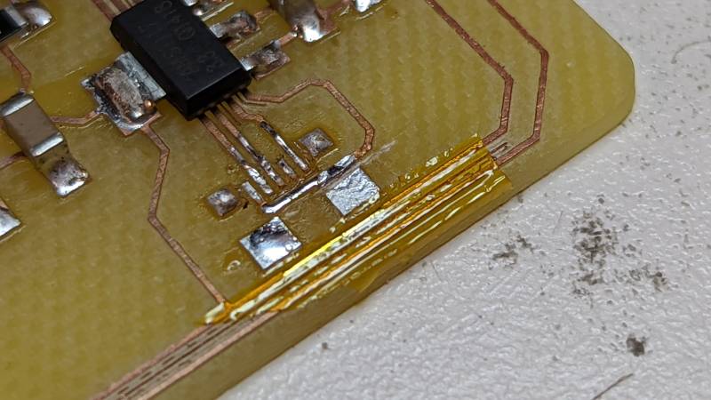
Same thing happened again: it’s when I realized the track was directly in contact with the USB port: again, I desoldered and look at it more carefully. When desoldering the first time a little bit of solder sticked to the port and when soldering after that it melt with the 5V track. It’s when I had the idea to use scotch to isolate the tracks. We have special scotch that can resist the heat, so I used that to isolate the tracks under the USB port. This time it worked like a charm.
The monster was born. Is it gonna be angry at its creator?
Programming
To program the ESP32 I needed to flash the SAMD11C with my SWD. I followed my own documentation to remember how to do it and uploaded Quentin’s program. After that I just had to select the right port in the Arduino IDE and I was able to program my little monster.
To program the ESP32, I need to:
- put it in Program mode by switching the commutator to the ground (to the left on my board)
- pushing the button one time
- upload a program
- switching the commutator in Run mode
- pushing the button to start
ESP32 ressources
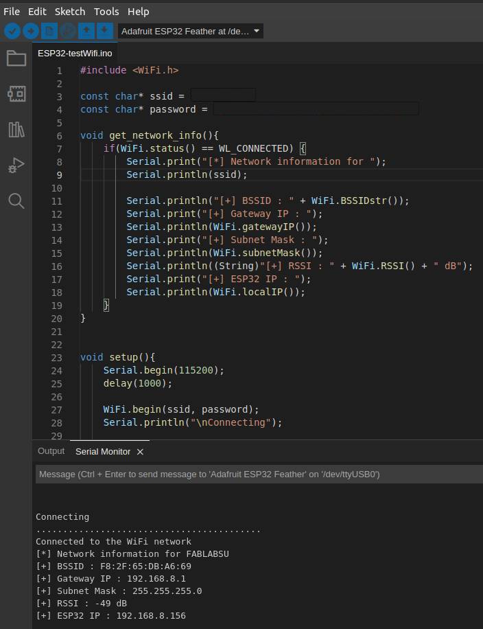
I first uploaded a simple program to test the Wi-Fi network to see if everything was going well, and thankfully no more surprises, it worked!
Networking
Now it was time to finally network! I wanted to explore the I2C protocol I want to use in my final project.
I2C protocol
I found a very helpful article explaining the I2C communication protocol between main and secondary boards. After reading it I was ready to program my boards an test them with an example. But it’s when I realized I forgot to add pull-up resistors for the I2C protocol. So I redid my little ATtiny board with the resistors and I added also an I2C connector: I will be able to use my first one as another address after all. Nothing is lost, apart for precious time.
Sending a signal (Main board)
  Wire.beginTransmission(I2C_ADDRESS);
  Wire.write('R');                      // One byte, but if I need more I can use pointers
  Wire.endTransmission();
Receiving a signal (Student board)
I learned that you need to do as few actions as possible in your receive function, as it plays with interrupts at the same time. Best practice is to change a variable and let the loop() take care of the rest. The variable needs to be volatile and must be defined outside of the loop() or setup() functions.
void receiveDataWire(int numBytes) {
char c = Wire.read();
switch (c) {
case 'R': // Red
ledTriggered = true;
r = 255;
g = 0;
b = 0;
break;
case 'G': // Green
ledTriggered = true;
r = 0;
g = 255;
b = 0;
break;
case 'B': // Blue
ledTriggered = true;
r = 0;
g = 0;
b = 255;
break;
case 'O': // Off
ledOff = true;
break;
}
And in the loop() I can then light the pixels.
void loop() {
if (ledTriggered) {
lightPixel(r,g,b);
ledTriggered = false;
}
if (ledOff) {
clearPixel();
ledOff = false;
}
}
Memory issues
I ran rapidly into an issue I didn’t anticipate (yet again, I don’t expect to anticipate much as I’m fairly new to all of this!). As I wanted to test the Wire library, the ATtiny ran out of memory very quickly, even with a simple code. I read the experience of a previous student and tried different libraries (as TinyI2C) to communicate in I2C, but none of them seemed really steady.
Space issue
Linking everything together...
/home/ejoz/.arduino15/packages/arduino/tools/avr-gcc/7.3.0-atmel3.6.1-arduino7/bin/avr-gcc -Wall -Os -g -flto -fuse-linker-plugin -Wl,--gc-sections -Wl,--section-start=.text=0x0 -mrelax -mmcu=attiny412 -o /tmp/arduino-sketch-E5350420058AF8CAC4C4C2997FB1EEE9/ATtiny412_secondary.ino.elf /tmp/arduino-sketch-E5350420058AF8CAC4C4C2997FB1EEE9/sketch/ATtiny412_secondary.ino.cpp.o /tmp/arduino-sketch-E5350420058AF8CAC4C4C2997FB1EEE9/libraries/Wire/twi.c.o /tmp/arduino-sketch-E5350420058AF8CAC4C4C2997FB1EEE9/libraries/Wire/twi_pins.c.o /tmp/arduino-sketch-E5350420058AF8CAC4C4C2997FB1EEE9/libraries/Wire/Wire.cpp.o /tmp/arduino-sketch-E5350420058AF8CAC4C4C2997FB1EEE9/libraries/tinyNeoPixel/tinyNeoPixel.cpp.o /tmp/arduino-sketch-E5350420058AF8CAC4C4C2997FB1EEE9/../arduino-core-cache/core_cac85e99a536e8525aa80710597bfff3.a -L/tmp/arduino-sketch-E5350420058AF8CAC4C4C2997FB1EEE9 -lm
/home/ejoz/.arduino15/packages/arduino/tools/avr-gcc/7.3.0-atmel3.6.1-arduino7/bin/../lib/gcc/avr/7.3.0/../../../../avr/bin/ld: address 0x1040 of /tmp/arduino-sketch-E5350420058AF8CAC4C4C2997FB1EEE9/ATtiny412_secondary.ino.elf section `.text' is not within region `text'
/home/ejoz/.arduino15/packages/arduino/tools/avr-gcc/7.3.0-atmel3.6.1-arduino7/bin/../lib/gcc/avr/7.3.0/../../../../avr/bin/ld: /tmp/arduino-sketch-E5350420058AF8CAC4C4C2997FB1EEE9/ATtiny412_secondary.ino.elf section `.rodata' will not fit in region `text'
/home/ejoz/.arduino15/packages/arduino/tools/avr-gcc/7.3.0-atmel3.6.1-arduino7/bin/../lib/gcc/avr/7.3.0/../../../../avr/bin/ld: address 0x1040 of /tmp/arduino-sketch-E5350420058AF8CAC4C4C2997FB1EEE9/ATtiny412_secondary.ino.elf section `.text' is not within region `text'
/home/ejoz/.arduino15/packages/arduino/tools/avr-gcc/7.3.0-atmel3.6.1-arduino7/bin/../lib/gcc/avr/7.3.0/../../../../avr/bin/ld: region `text' overflowed by 146 bytes
collect2: error: ld returned 1 exit status
Using library Wire at version 2.0.6 in folder: /home/ejoz/.arduino15/packages/megaTinyCore/hardware/megaavr/2.5.11/libraries/Wire
Using library tinyNeoPixel at version 2.0.4 in folder: /home/ejoz/.arduino15/packages/megaTinyCore/hardware/megaavr/2.5.11/libraries/tinyNeoPixel
Compilation error: exit status 1
I decided to try my prefered method of debugging: comment and uncomment lines one by one and see what’s causing the issue. It turned out the Serial library was causing all this trouble! Once removed all traces of it, I was able to upload the code properly, without too much space taken.
Hardware setup and sending a character
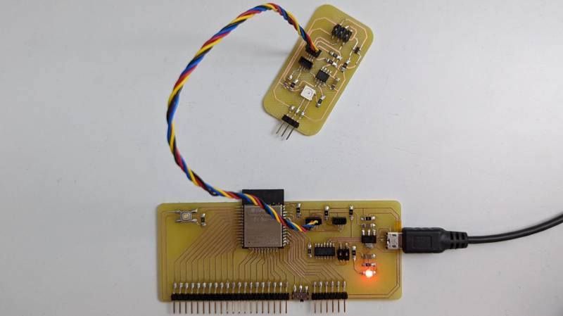
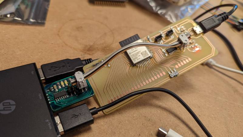
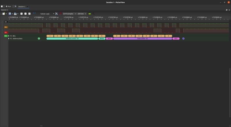
I then connected my two board via the Qwiic connectors and tested the all thing, but nothing happened. I used my Logic Analyzer to try to understand what was going on, but I was unable to read any signal on the clock line (SCL). Stephane found an article that suggested to add more informations in the main setup() loop, as the SDA and SCL pins and the clock for example.
#include <Wire.h>
void setup() {
Wire.begin(21, 22); // Indication of SDA and SCL pins
Wire.setClock(100000); // Clock to 100kHz
}
And then the signal was read by the Logic Analyzer! I almost cried Eureka but I my RGB led did not seem to work, even with the signal now working as expected. Digging the internet (here and here), I found that the interrupts timing of the RGB leds and of the Wire library seemed to be incompatible… There seems to be some solutions but I don’t think I’m able to create an easy fix for now.
Solution: tinyNeoPixel_Static
During Regional Review I talked about my issue: thanks to the power of distributed education someone had run into the same issue and solved it already! Bas was my saviour this week, and he did a marvelous job talking to his student boards. I immediatly tried his fix, which turns out to be a different version of the tinyNeopixel library, the tinyNeoPixel_Static.
tinyNeoPixel_Static library specifications by SpenceKonde
tinyNeoPixel_Static is slightly cutdown, removing the option to change the length or type of pixels at runtime (which relies on dynamic memory allocation). Instead it requires the user to manually declare the pixel array and pass it to the tinyNeoPixel constructor. Additionally, it does not set the pinMode of the pin (the sketch must set this as OUTPUT); - the reason for this was that it is a no-holds-barred attempt to cut the flash consumption as much as possible, Removing that last pinMode cuts out over 100 bytes, which is nothing to sneeze at on the tiniest of tinies! Note that the savings requires eliminating all calls to pinMode and replacing them with writes toVPORTx.DIR registers (if you have to set only a small number of bits in one of those, and everything is known at compile time, you’re often better with several consecutive |= operators each setting one bit, because those end up as a single-word SBI or CBI - while |= for more than 1 bit requires a read/modify/write (IN, ORI, OUT, which must be done with interrupts disabled if any interrupts modify the same register. Finally, no call to begin() should be made, nor can it be made. These changes reduce sketch size and provide greater visibility on the memory usage. Unless you need to change string length or type at runtime, it is recommended that tinyNeoPixel_Static be used - it uses less flash, particularly if you don’t use malloc elsewhere (I try to avoid it - the core certainly doesn’t, nor, to my knowledge, do any of the included libraries!
I just had to change the library name and to call out the pinMode(), and it worked! I love being in a distributed network.
Final code
#include <Wire.h>
#define I2C_ADDRESS 42
void setup() {
Wire.begin(21, 22);
Wire.setClock(100000);
Serial.begin(115200);
}
void loop() {
sendDataWire('R');
delay(1000);
sendDataWire('G');
delay(1000);
sendDataWire('B');
delay(1000);
sendDataWire('O');
delay(1000);
}
void sendDataWire(char c) {
Wire.beginTransmission(I2C_ADDRESS);
Wire.write(c);
Wire.endTransmission();
}
#include <Wire.h>
#include <tinyNeoPixel_Static.h>
#define ADDRESS 42
#define PIN 4 // PA3
#define NUMPIXELS 25 // Do not put more than 25 leds
byte pixels_byte[NUMPIXELS * 3];
tinyNeoPixel pixels = tinyNeoPixel(NUMPIXELS, PIN, NEO_GRB, pixels_byte);
volatile uint8_t ledTriggered = false;
volatile uint8_t ledOff = false;
volatile uint8_t r, g, b;
void setup() {
pinMode(PIN, OUTPUT);
pixels.show();
Wire.begin(ADDRESS);
Wire.onReceive(receiveDataWire);
}
    void loop() {
        if (ledTriggered) {
            lightPixel(r,g,b);
            ledTriggered = false;
        }

        if (ledOff) {
            clearPixel();
            ledOff = false;
        }
    }
void receiveDataWire(int numBytes) {
char c = Wire.read();
switch (c) {
case 'R':
ledTriggered = true;
r = 255;
g = 0;
b = 0;
break;
case 'G':
ledTriggered = true;
r = 0;
g = 255;
b = 0;
break;
case 'B':
ledTriggered = true;
r = 0;
g = 0;
b = 255;
break;
case 'O':
ledOff = true;
break;
}
}
void lightPixel(int r, int g, int b) {
pixels.fill(pixels.Color(r, g, b));
pixels.show();
}
void clearPixel() {
pixels.clear();
pixels.show();
}
About this week
At the end of the week I was a little discouraged because I wasn’t able to make my network work. I presented my work in Regional Review and asked if anyone had any suggestions about my issue with the tinyNeoPixel library, and the magic happened. I really want to say thank you to Bas, who not only saved my week but also tought me good practices from his documentation.
I was also happy to present my monster board to Global after Quentin put the light on it. Even if it’s not a beautifully designed one, the fact that it uses the SAMD11C with Quentin’s code to be programmed makes it special.
You can watch every classes online, and this week’s below. The monster board is presented at 01:30:08.