Interface & Applications
- Write an application that interfaces a user with an input &/or output device that you made
- Compare as many tool options as possible
Warning
I came back using Arduino IDE 1.8 because the 2.0 version is not yet compatible with everything I tried this week. Moreover, the Serial Monitor kept printing weird values when using the ESP32, and I thought for a long time that it was a hardware issue.
Dabble
Thanks to Aurore who presented her work in Regional Review, I discovered Dabble. Dabble works with Bluetooth, and I wanted to test it with my ESP32 board made in Networking week to see if I could control the lightning of the leds.
Spoiler: It was very easy, but it’s kind of a black box.
Setup & tests
The first thing you need to do is download the app on your smartphone (Android is recommanded).
Then you need to download the Dabble ESP32 library in the Arduino IDE. You can do it directly from the Library Manager.
When it’s done, you can upload one of the test code in your ESP32 to test if everything is working. I recommand testing the Terminal Module, as it’s the more customizable afterwards.
Et voilà! You can now communicate via Bluetooth with your ESP32.
Having fun with LEDs
Once I tested the basics, I tried to make things a little more interesting. As I already programmed my network last week, I wanted to trigger the leds via bluetooth. The only thing you need to do is get the data from the app and after that everything work as usual.
void loop() {
    Dabble.processInput();                  // Dabble need this line to get the data you send from your smartphone

    if (Terminal.compareString("red")) {    // A simple condition to trigger an event you chose
    Wire.beginTransmission(I2C_ADDRESS);
    Wire.write('R');
    Wire.endTransmission();
    }
}
You can find the entire code below. I can now control my LEDs via bluetooth!
#include <Wire.h>
#include <DabbleESP32.h>

#define CUSTOM_SETTINGS
#define I2C_ADDRESS 42

void setup() {
  Wire.begin(21, 22);
  Wire.setClock(100000);

  Dabble.begin("ESP32_WROOM_32E");
}

void loop() {
  Dabble.processInput();

  if (Terminal.compareString("red")) {
    sendDataWire('R');
  }

  if (Terminal.compareString("green")) {
    sendDataWire('G');
  }

  if (Terminal.compareString("blue")) {
    sendDataWire('B');
  }

  if (Terminal.compareString("off")) {
    sendDataWire('O');
  }
}

void sendDataWire(char c) {
  Wire.beginTransmission(I2C_ADDRESS);
  Wire.write(c);
  Wire.endTransmission();
}
As fun as it was, I will not use Dabble in my final project, as I want it to be as personalsed as it could be. But for a simple project, Dabble can be really helpful. The only thing I regretted was the impossibility to create an app myself.
ESP Dash
I also tested quickly ESP-Dash as a way to host a web interface directly in the ESP32.
I followed their Getting started tutorial and then build my own interface to control the leds. It was fun to do, but again, kind of a black box.
Dependencies
Don’t forget to install these libraries into your IDE before compiling your program. These can be installed via Sketch > Include Library... > Add .ZIP Library...
- ESP32 Arduino Core - (latest)
- AsyncTCP - v1.0.3
- ESPAsyncWebServer - v1.2.3
- ArduinoJson - v6.17.0
Code
#include <WiFi.h>
#include <AsyncTCP.h>
#include <ESPAsyncWebServer.h>
#include <ESPDash.h>

/* Your WiFi Credentials */
const char* ssid = "SSID";
const char* password = "PASSWORD";

/* Start Webserver */
AsyncWebServer server(80);

/* Attach ESP-DASH to AsyncWebServer */
ESPDash dashboard(&server);

/*
  Dashboard Cards
  Format - (Dashboard Instance, Card Type, Card Name, Card Symbol(optional) )
*/
Card buttonR(&dashboard, BUTTON_CARD, "RED");
Card buttonG(&dashboard, BUTTON_CARD, "GREEN");
Card buttonB(&dashboard, BUTTON_CARD, "BLUE");

#include <Wire.h>

#define I2C_ADDRESS 42

void setup() {
  Wire.begin(21, 22);
  Wire.setClock(100000);

  Serial.begin(115200);

  /* Connect WiFi */
  WiFi.mode(WIFI_STA);
  WiFi.begin(ssid, password);
  if (WiFi.waitForConnectResult() != WL_CONNECTED) {
      Serial.printf("WiFi Failed!\n");
      return;
  }
  Serial.print("IP Address: ");
  Serial.println(WiFi.localIP());

  /* Start AsyncWebServer */
  server.begin();
}

void loop() {
  buttonR.attachCallback([&](bool value){
    Serial.println("[buttonR] Button Callback Triggered: "+String((value)?"true":"false"));
    if (value) {
      sendDataWire('G');
    }
    else {
      sendDataWire('O');
    }
    buttonR.update(value);
  });

  buttonG.attachCallback([&](bool value){
    Serial.println("[buttonG] Button Callback Triggered: "+String((value)?"true":"false"));
    if (value) {
      sendDataWire('R');
    }
    else {
      sendDataWire('O');
    }
    buttonG.update(value);

  });

  buttonB.attachCallback([&](bool value){
    Serial.println("[buttonB] Button Callback Triggered: "+String((value)?"true":"false"));
    if (value) {
      sendDataWire('B');
    }
    else {
      sendDataWire('O');
    }
    buttonB.update(value);

  });

  dashboard.sendUpdates();
  delay(10);
}


void sendDataWire(char c) {
  Wire.beginTransmission(I2C_ADDRESS);
  Wire.write(c);
  Wire.endTransmission();
}
Video
Once running, you can access the I.P. address of your ESP32 (it will be printed in your Serial Monitor).
Web Serial with ESP32
The WebSerial library can be downloaded from the Library Manager in Arduino IDE. It allows the ESP to communicate in Serial through a web server stored in the program memory of the microcontroller.
Code
I worked based on the example code of the WebSerial library, and you can find tutorials here adnd here.
#include <WiFi.h>
#include <AsyncTCP.h>
#include <ESPAsyncWebServer.h>
#include <WebSerial.h>

const char* ssid = "SSID";
const char* password = "PASSWORD";

/* Start Webserver */
AsyncWebServer server(80);

#include <Wire.h>
#define I2C_ADDRESS 42

void setup() {
  Wire.begin(21, 22);
  Wire.setClock(100000);

  Serial.begin(115200);

  /* Connect WiFi */
  WiFi.mode(WIFI_STA);
  WiFi.begin(ssid, password);
  if (WiFi.waitForConnectResult() != WL_CONNECTED) {
      Serial.printf("WiFi Failed!\n");
      return;
  }
  Serial.print("IP Address: ");
  Serial.println(WiFi.localIP());

  // WebSerial is accessible at "<IP Address>/webserial" in browser
  WebSerial.begin(&server);

  /* Attach Message Callback */
  WebSerial.msgCallback(recvMsg);

  /* Start AsyncWebServer */
  server.begin();
}

void sendDataWire(char c) {
  Wire.beginTransmission(I2C_ADDRESS);
  Wire.write(c);
  Wire.endTransmission();
}

/* Message callback of WebSerial */
void recvMsg(uint8_t *data, size_t len){
  WebSerial.println("Received Data...");
  String d = "";
  for(int i=0; i < len; i++){
    d += char(data[i]);
  }
  WebSerial.println(d);

  if (d == "red") {sendDataWire('G');}
  if (d == "green") {sendDataWire('R');}
  if (d == "blue") {sendDataWire('B');}
  if (d == "off") {sendDataWire('O');}
}

void loop() {}
Video
MicroPython with ESP32
This doesn’t work for now
Spoiler alert: I couldn’t make MicroPython work on my ESP32. This paragraph is just here to remind me the steps I took to try it and hopefully make it work another time.
I first downloaded the firmware and installed esptool.
I followed the documentation to erase the flash memory of the ESP32 and upload the firmware on it.
ejoz@ejoz-xps-13:~/Desktop/MicroPython$ esptool.py --chip esp32 --port /dev/ttyACM0 erase_flash
esptool.py v3.3
Serial port /dev/ttyACM0
Connecting.............................
Chip is ESP32-D0WD-V3 (revision 3)
Features: WiFi, BT, Dual Core, 240MHz, VRef calibration in efuse, Coding Scheme None
Crystal is 40MHz
MAC: 8c:4b:14:a3:9d:ec
Uploading stub...
Running stub...
Stub running...
Erasing flash (this may take a while)...
Chip erase completed successfully in 20.8s
Hard resetting via RTS pin...
ejoz@ejoz-xps-13:~/Desktop/MicroPython$ esptool.py --chip esp32 --port /dev/ttyACM0 write_flash -z 0x10000 esp32-20220117-v1.18.bin
esptool.py v3.3
Serial port /dev/ttyACM0
Connecting...
Chip is ESP32-D0WD-V3 (revision 3)
Features: WiFi, BT, Dual Core, 240MHz, VRef calibration in efuse, Coding Scheme None
Crystal is 40MHz
MAC: 8c:4b:14:a3:9d:ec
Stub is already running. No upload is necessary.
Configuring flash size...
Flash will be erased from 0x00010000 to 0x0018bfff...
Compressed 1555136 bytes to 1022998...
Wrote 1555136 bytes (1022998 compressed) at 0x00010000 in 90.2 seconds (effective 137.9 kbit/s)...
Hash of data verified.

Leaving...
Hard resetting via RTS pin...
At this point everything was doing ok but I was worried to not be able to go back and upload an Arudino code on it again. A little late to worry, but anyway, I searched online and found out you just have to reset the board and upload a new sketch via the Arduinon IDE.
I then followed a tutorial to use MicroPython in VSCode thank to an extension called Pymakr.
And then the problems started. I wasn’t able to detect the board via the serial ports. Even though in the Arduino IDE the SAMD11C wasn’t a problem, I think that might be the issue here.
Found 0 serialports
Please connect to your device
Please connect to your device

Searching for PyCom boards on serial...
No PyCom boards found on USB
Connecting to dev/ttyACM0...
No PyCom boards found on USB
So I found that it was possible to open a REPL in an emulated terminal. I downloaded picocom with apt-get and tried it. It seems fine, but when I try to hit Enter to open the REPL, nothing happens.
ejoz@ejoz-xps-13:~/Desktop/MicroPython$ picocom /dev/ttyACM0 -b115200
picocom v3.1

port is        : /dev/ttyACM0
flowcontrol    : none
baudrate is    : 115200
parity is      : none
databits are   : 8
stopbits are   : 1
escape is      : C-a
local echo is  : no
noinit is      : no
noreset is     : no
hangup is      : no
nolock is      : no
send_cmd is    : sz -vv
receive_cmd is : rz -vv -E
imap is        :
omap is        :
emap is        : crcrlf,delbs,
logfile is     : none
initstring     : none
exit_after is  : not set
exit is        : no

Type [C-a] [C-h] to see available commands
Terminal ready
I also tried ampy without success. I check a thousand time if it was the right port, but nothing.
ejoz@ejoz-xps-13:~/Desktop/MicroPython$ ampy --port /dev/ttyACM0 ls
^C
Aborted!
I also tried putty, but nothing happens when I try to open the serial terminal. I think all my search are in vain because of the SAMD11C making the serial connection.
I finally gave up after more than an afternoon of searching. I wanted to do my interface, and it will be in C++. I’m a little disappointed because I love python, but I will try again. If the problem comes from the SAMD11C, I think I will try with another board.
Final project interface
This week I want to make the interface for my final project: even if it’s a diorama and I want to keep things simple, I would like to have a way to quickly test light effect to work on some of the scenarii I have in mind. So an interface would be a perfect tool to do that: listen at the music and testing live some effects by simply pushing a button on my phone without having to compile every time I make a change: what a dream !
As a first spiral I want to build the interface, and maybe, find a way to store the effects I’m launching to keep a scenario in memory? But more on that later.
SPIFFS
After having fun with easy interface tools on the beginning of the week and failing to get MicroPython working on my ESP32, I looked into more efficient ways to create a web interface. I found tons of example but kind of unreadable: the html was written directly in the .ino file and I didn’t like that at all. Otherwise the principle stayed as simple as the rest. As soon as you had AsyncTCP and ESPAsynchWebServer installed, it seemed easy enough to deploy a webpage.
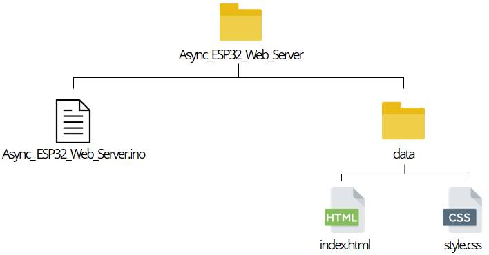
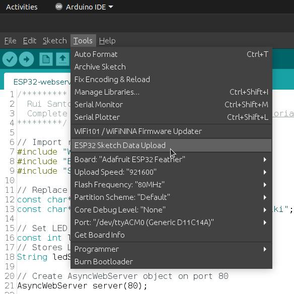
I finally found a system that answered my need to keep things organized: SPIFFS, or Serial Peripheral Interface Flash File System. I followed a tutorial to install the filesystem uploader in my Arduino IDE: I just need to respect a simple rule when uplaoding my files: keep everything under a data/ folder (as shown in the schematic below).
Now I can upload files into the flash memory of the ESP32 and can keep things organized (I love it). To upload my files, I need to put the ESP in waiting for download mode and push the reset button.
[SPIFFS] data   : /home/ejoz/Arduino/ESP32-webserver/data
[SPIFFS] start  : 2686976
[SPIFFS] size   : 1472
[SPIFFS] page   : 256
[SPIFFS] block  : 4096
/index.html
/style.css
[SPIFFS] upload : /tmp/arduino_build_234978/ESP32-webserver.spiffs.bin
[SPIFFS] address: 2686976
[SPIFFS] port   : /dev/ttyACM0
[SPIFFS] speed  : 921600
[SPIFFS] mode   : dio
[SPIFFS] freq   : 80m

esptool.py v2.9-dev
Serial port /dev/ttyACM0
Connecting........_____....._____
I then tested the workflow with some tutorials (like this one or this one and get it to work quickly: now the fun begins, because I need to adapt this system to my final project.
To add SPIFFS to your project, you just have to add these lines to your setup() function.
// SPIFFS
if (!SPIFFS.begin()) {
Serial.println("SPIFFS error...");
return;
}

File root = SPIFFS.open("/");
File file = root.openNextFile();

while (file) {
Serial.print("File: ");
Serial.println(file.name());
file.close();
file = root.openNextFile();
}
ESP32 as Soft Access Point
These tutorials were great to understand the process, but I would like to store the network in the ESP32. I tested the ESP32 as a Soft Access Point and it worked. The most important lines are to be put in the setup() function as usual. The SSID is the network that you’re building from the ESP32, and you need the password to connect to it. It’s optionnal to add a password, and if the diorama was made to be in an interactive exposition I think I would let the network open, but for now I think it’s good practice to keep a password. Don’t forget to print the IP address in the Serial Monitor, otherwise you won’t know which page to connect to. In my case it’s 192.168.4.1, and I think it’s a standard for the ESP32.
Asynchronous server
Now that our ESP works as a Soft Access Point, we can add all that makes an interface: interaction with user! I have to keep in mind to not add too many things because every file is stored in the flash memory.
The key is the ESPAsyncWebServer library, that allows multiple connections adn simplifies the requests. I don’t understand how everything works yet, but it seems obvious that it was a really good choice for my use.
Warning
- This library does not work inside the loop, so all the requests are to be handled in the
setup()function. - Do not use
delay()oryield() - No more than one response to a single request
// Server requests
server.on("/", HTTP_GET, [](AsyncWebServerRequest *request) {
    request -> send(SPIFFS, "/index.html", "text/html");
});

server.on("/w3.css", HTTP_GET, [](AsyncWebServerRequest *request) {
    request -> send(SPIFFS, "/w3.css", "text/css");
});

server.on("/script.js", HTTP_GET, [](AsyncWebServerRequest *request) {
    request -> send(SPIFFS, "/script.js", "text/javascript");
});

server.begin();
I followed an excellent tutorial (it’s in french sadly, but I couldn’t find the equivalent in English) that explained how to use the AsyncTCP library with SPIFFS and javascript. I followed it and found the base perfect for my needs.
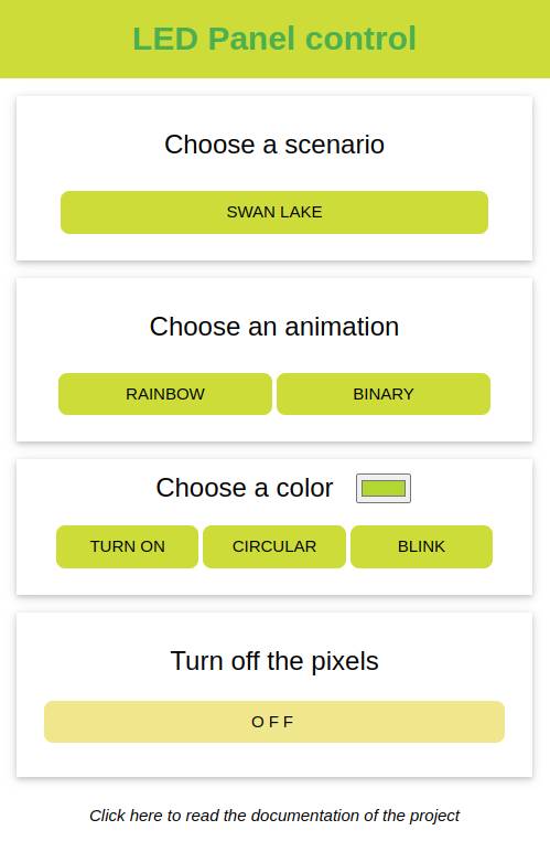
Building the interface
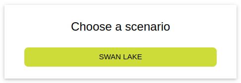
Combining all that I learned, I made my own interface.
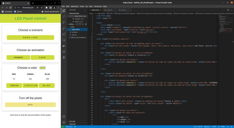
I made a pretty simple interface using W3.CSS. It’s easier for me to start with an existing CSS and modify what I need later. Plus it’s not really the focus on the week, so I hope it’s ok. I also found a very useful tool to reduce the size of the CSS file in the end and take less memory of the ESP.
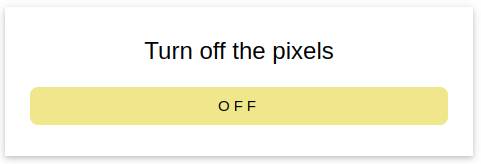
So I started simple by adding a button to turn off the LEDs.
The button is calling a javascript function that send an http request.
function offButton() {
    var xhttp = new XMLHttpRequest();
    xhttp.open("GET", "off", true);
    xhttp.send();
}
This request is then treated in the C++ code with the help of ASyncWebServer. I then call the I2C function sendCommand() and send a byte to trigger the student board.
server.on("/off", HTTP_GET, [](AsyncWebServerRequest *request) {
    sendCommand('O');
    request -> send(200);
});
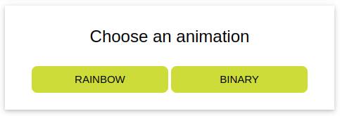
The next buttons were a little trickier. I handled the function onclick="command(0)" with integers as arguments because I was unable to treat them server-side.
function command(scenario) {
    var xhttp = new XMLHttpRequest();
    xhttp.open("GET", "/scenario" + "?=" + scenario, true);
    xhttp.send();

    console.log("GET", "/scenario" + "?=" + scenario);
}
The switch() is not capable of handling String values, so as I didn’t have that many effect to trigger, I chose to stay simple and kept integers. I needed to convert them first, because the getParam() function gives a pointer to a String.
  server.on("/scenario", HTTP_GET, [](AsyncWebServerRequest *request) {
    AsyncWebParameter* p = request->getParam(0);
    int param;
    param = p->value().toInt();

    switch (param) {
      case 0:
        sendCommand('S'); // Scenario
        break;
      case 1:
        sendCommand('R'); // Rainbow
        break;
      case 2:
        sendCommand('Y'); // Binary
        break;
    }

    request -> send(200);
  });
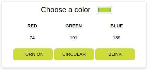
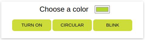
And I was done with the easy part. For the next, you can trust me if I say I spent more than a day figuring out how to pass correctly the information of the color choice. I first only wanted to trigger specific animations to keep things simple, but I found out that the <input type="color"> in HTML could allow me to send color information directly from the user to the LEDs. If you have read some of my previous weeks, you know I couldn’t have stop there, I needed to try.
I first struggled a lot with javascript, as it is really unknown territory to me. But a lot of googling made me on the right path and I could extract the RGB values picked by the input after a lot of tries.
var choose_color = document.getElementById("color_picker");
var hex_code = choose_color.value.split("");
var red = parseInt(hex_code[1] + hex_code[2], 16);
var green = parseInt(hex_code[3] + hex_code[4], 16);
var blue = parseInt(hex_code[5] + hex_code[6], 16);
I then displayed them in the screen dynamically thanks to .innerHTML, but it was only for debugging, I didn’t keep that in the end.
document.getElementById("rColor").innerHTML = red;
document.getElementById("gColor").innerHTML = green;
document.getElementById("bColor").innerHTML = blue;
After that I just had to send a GET request to the server with multiples arguments.
var xhttp = new XMLHttpRequest();
xhttp.open("GET", "/" + effect + "?r=" + red + "&g=" + green + "&b=" + blue, true);
xhttp.send();
On the .ino file, I got the parameters of the request by reading this tutorial and the ESPAsyncWebServer reference. And to send them, I needed to convert them in the right format. This took me forever to understand: I knew I should probably use uint8_t format because it can contain values from 0 to 255 and it’s only one byte (which is that I2C controls best), but I had no clue how to convert the getParam into uint8_t. I finally asked Bas for help because I didn’t know what to do, everything I tried was a fail. He taught me that you can easily convert values with a simple (uint8_t) in front of the value you want to convert! He wrote a tutorial about that for his colleagues in Waag, I learned a lot.
server.on("/on_rgb", HTTP_GET, [](AsyncWebServerRequest *request){
    AsyncWebParameter* r = request->getParam(0);
    AsyncWebParameter* g = request->getParam(1);
    AsyncWebParameter* b = request->getParam(2);

    red = (uint8_t)r->value().toInt();
    green = (uint8_t)g->value().toInt();
    blue = (uint8_t)b->value().toInt();

    sendColor('T', red, green, blue);

    request->send(200);
});
I used a new function sendColor() I wrote to send the information to the student board with the LEDs. It sends four bytes: one char and three uint8_t.
void sendColor(char c, uint8_t r, uint8_t g, uint8_t b) {
    Wire.beginTransmission(I2C_ADDRESS);
    Wire.write(c);
    Wire.write(r);
    Wire.write(g);
    Wire.write(b);
    Wire.endTransmission();
}
In the receiver board, I had to declare my variables right in the beginning of the file, before the setup() function where I call the Wire.onReceive(receiveDataWire);.
On the function receiveDataWire(), I read the first byte and according to it I can know if there are more to read or not. According to these informations, I trigger the corresponding animation. You can read more about those in the section below.
void receiveDataWire(int numBytes) {
    char c = Wire.read();

    switch(c) {
    case 'T':                         // Turn on with RGB values
        scenario = 'T';
        ri2c = Wire.read();
        gi2c = Wire.read();
        bi2c = Wire.read();
        break;
    case 'O':                         // OFF
        scenario = 'O';
        break;
    }
    t = 0;
}
And voilà, I have a working interface.
Reprogramming the NeoPixel
When programming the ATtiny to respond to I2C calls by the ESP32 (you can see it in the Networking week), I ran into an issue: it’s fine for the ATtiny to receive a simple task to do like light all pixels in red, but as soon as I wanted to try more complicated effects as rainbows or blinking, it became deaf to any other calls and got stuck in the light animation. For my final project I want to be able to program any effects I want, and call them in a scenario way.
Clock control
I read a serie of articles about how to use millis() to multi-task the MCU and try to be more effective when calling the leds animation. I then modify the structure of my code to avoid using any delay() in it.
When receiving a message from the main board, the ATtiny change a variable called scenario according to the byte received. I then use a switch to trigger an effect. Below you can see the main loop of the program: I use the internal clock of the MCU to count the milliseconds. Each ten milliseconds (an arbitrary interval, it could be longer), I execute a command according to the scenario defined. I then increment t, a variable that allows me to animate the LEDs (I will explain in the next paragraph why).
This way, I can receive another message while the LEDs are doing something, and change the scenario variable on the fly, being always aware of changes triggered by the interface.
void loop() {
  unsigned long currentMillis = millis();           // I check the internal clock

  if (currentMillis - previousMillis > interval) {  // If the clock is beyond the interval predefined, the program changes (or continues)
    previousMillis = currentMillis;                 // I update the time

    switch (scenario) {                             // According to the scenario variable, the LEDs are in  a different animation
      case 'R':                                     // "Rainbow" scenario
        rainbowEffect(t, ALL);
        pixels.show();
        tMax = 3000; // 30s                         // tMax is here to turn off the LEDs after 30s of inactivity
        break;
      case 'O':                                     // Off
        turnOff(ALL);
        pixels.show();
        break;
    }

    if (t >= tMax) {
      scenario = 'O';
      t = 0;                                        // Reset the t every time the LEDs turn off for inactivity
    }
    else {
      t++;                                          // t is incremented every 10 milliseconds
    }
  }
}
NeoPixels animations
The NeoPixels are a very versatile tools, but sometimes hard to bend to your will. If you read the previous assignments you saw me struggling with them during Embedding programming week, Output week and Networking week.
This time I was determined to not use any delay() and to make them do fun animations. As a reminder, the tinyNeoPixel_Static that I use is based on the Adafruit_NeoPixel API, so I can use the same functions.
It’s important to know that to light the NeoPixel you have to use the show() function. This function appears only in the main loop of my program, and the colors and animationsa are taking care of in the sub-functions.
I first wrote two simple functions to turn on and off the LEDs. The function loops other each pixel and turn them on or off. I added a ledSection argument to decide wich part of the strip should be affected by the command. It will allow me to make asynchronous animations for the scenarii.
void turnOff(int ledSection[]) {
  /*
   * Turn off a defined Section of LEDs
   */
  for (int i = ledSection[0]; i <= ledSection[1]; i++) {
    pixels.setPixelColor(i, pixels.Color(0, 0, 0));
  }
}
void turnOnRGB(int ledSection[], int r, int g, int b) {
  /*
   * Turn on a defined section of LEDs with RGB Color
   * R, G, B : 0 to 255
   */
  for (int i = ledSection[0]; i <= ledSection[1]; i++) {
    pixels.setPixelColor(i, pixels.Color(r, g, b));
  }
}
The sections are defined in global with arrays of two numbers: the first and last LED of the section.
I also wanted to use the HSV color space for some specific animations, like fading effects. I learned that this space is particular for the NeoPixel and had to remap the values from 0 and 360 to 0 and 65536. I used this Color Picker to convert some values at first.
void turnOnHSV(int ledSection[], int h, int s, int v) {
  /*
   * Turn on a defined section of LEDs with HSV Color
   * H: 0 to 65536
   * S: 0 to 255
   * V: 0 to 255
   */
  int hue = map(h, 0, 360, 0, 65536);                       // Map HSV value
  for (int i = ledSection[0]; i <= ledSection[1]; i++) {
    pixels.setPixelColor(i, pixels.ColorHSV(hue, s, v));
  }
}
I used the t variable to calculate the state of each NeoPixel on the fly and light them accordingly. For example, you can see below in the rainbowEffect that I use t to vary the hue of the LEDs. I made other functions that uses t as well.
void circularEffect(int t, int ledSection[], int r, int g, int b) {
    /*
    * Light every LED one by one and start again
    */
    int numberLeds = ledSection[1] - ledSection[0];

    for (int i = ledSection[0]; i <= ledSection[1]; i++) {
            if ((t % numberLeds) + ledSection[0] == i) {
            pixels.setPixelColor(i, pixels.Color(r, g, b));
        }
        else {
            pixels.setPixelColor(i, pixels.Color(0, 0, 0));
        }
    }
}
void fadeEffect(int t, int ledSection[], int hue) {
    /*
    * Varies the brightness value between 0 and 255.
    * Using cosinus and trigonometric circle.
    */
    double angle = (float) (t % 628) / 100;           // Map time to angle
    double valueDouble = (-cos(angle) + 1.0) * 128.0; // Compute cosinus and map value between 0 and 255
    int value = ((int) valueDouble) % (256);          // Transforms value in integer
    turnOnHSV(ledSection, hue, 255, value);           // Turn all defined leds to hue, maximum saturation and value
}
My girlfriend is a computer scientist and we had some fun programming animations with the LEDs over the week-end. She went crazy when she saw that with the ATtiny we couldn’t print any indications, so she had the ideo to monitor the t value thanks to a binary clock. It turned out to be a great help and a beautiful animation, so I kept it in the final code.
void binaryEffect(int t) {
  /*
   * Binary count with 16 leds (2^16-1)
   */
  int tt = t;
  for (int i = 1; i <= 17; i++) {
    if (tt % 2 == 0) {
      pixels.setPixelColor(i, pixels.Color(0,0,0));
    }
    else {
      pixels.setPixelColor(i, pixels.Color(127, 127, 127));
    }
    tt = tt / 2;
  }
}
Asynchronously build a scenario
As I love to make dioramas with scenarii since before Fab Academy, I already had a music in mind to animate it. I found the Swan Lake music really resourceful for a light and music show, and I will try to highlight the music with light effects as well as I can. This is open source music so I know I will not have issues using it in my project. The idea is to make the workflow of creating a scenario for a music easier, so later I will be able to make more scenarii with other musics.
Each scenario will be structured like this one below: every t the pixels are cleared, set to their new color according to the animation, and showed.
void swan(int t) {
  /*
   * Swan Lake music
   */
  pixels.clear();                             // Reinitialize all LEDs

  /*
   * Start of the scenario
   */

  if (effectDuration(t, 0, 30000)) {
    rainbowEffect(t, SECTION1);
  }

  if (effectDuration(t, 0, 30000)) {
    circularEffect(t, SECTION2, 89, 123, 87);
  }

  /*
   * End of the scenario
   */
  pixels.show();                              // Show the color for each t
}
I created a useful function to give a start and stop time to each animation, using t as always.
bool effectDuration(int t, int tStart, int tStop) {
  /*
   * Implement the effect for a given time
   */
  if ((t >= tStart) && (t < tStop)) {
    return true;
  }
  return false;
}
This way it’s possible to make the LEDs act asynchronously, and light only certain sections of the diorama, or make them do different things at the same time.
Video demonstration
Memory issues
When adding animations to the program I was warned regularly that the memory was almost overflowed. Today the program can not run properly if I test all the animations. For example, the fadeEffect eats too much memory and I can only use it for testing purpose. This made me think about the architecture I decided to do in Networking week: I will probably use an ATtiny 3216 for the final version, to be able to use the LEDs at their full capabilities. Moreover, I need to test some power supplies to see if I can use more than 25 LEDs.
Warning
Other things that I didn’t have time to investigate
About this week
My videos were too large this week, so I modified the ffmpeg command I used before by this one (assuming the sound were already removed from the vieo): ffmpeg -i input.mp4 -vcodec libx264 -crf 28 -vf scale=1280:-1 output.mp4. The final video is still 5Mb, but as I haven’t too many images this week I hope it’s ok. I dread the time coming of the final project video editing. I’m not used to do this and I juste tested ShotCut this week but it was minimal editing.