14. Networking and communications
This week I worked on networking and communications. I specifically worked on adding an ESP32 Wroom Bluetooth module to my board. Here are the assignments :
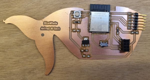
Hero shot
ESP32 Wroom Datasheet
I chose to use a ESP32 Wroom module because we have it at Agrilab.
Here are some specifications from the datasheet:
“ESP32-WROOM-32 is a powerful, generic Wi-Fi+BT+BLE MCU module that targets a wide variety of applications, ranging from low-power sensor networks to the most demanding tasks, such as voice encoding, music streaming and MP3 decoding.”
It’s composed of an ESP32-D0WDQ6 chip which has some caracteristics like :
- 2.4 GHz Wi-Fi and Bluetooth combo chip
- TSMC ultra-low Power 40nm technology (fine-grained clock gating, multiple power modes, and dynamic power scaling)
- 2 CPU cores that can be individually controlled. The CPU clock frequency is adjustable from 80MHz to 240Mhz. The CPU can be powered off by the user and the low-power processor can be used to monitor the peripherals for changes or crossing thresholds.
What is Bluetooth Low Energy (BLE) and how can it improve the battery consumpion when using Bluetooth ?
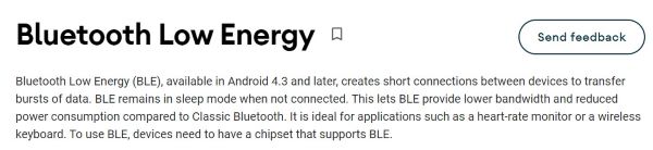
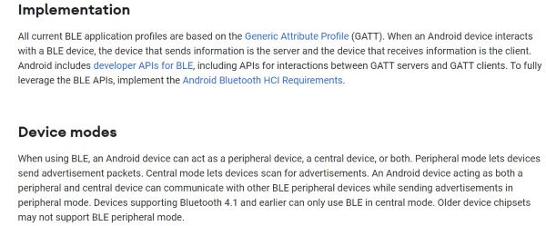
From Source Android
Group Assignment with Luc Hanneuse Agrilab
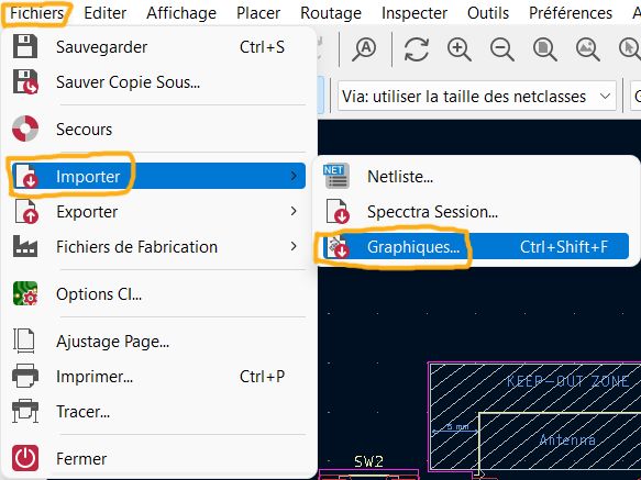
Adding the ESP32 Arduino IDE Board Manager URL :
- Go to this ESP32 Arduino IDE tutorial
- Copy the ESP32 Arduino IDE Board Manager URL
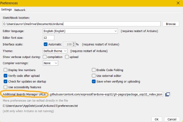
- Open your Arduino IDE
- Go to “file” > “preferences” and paste it into the “Additional Manager URLs”
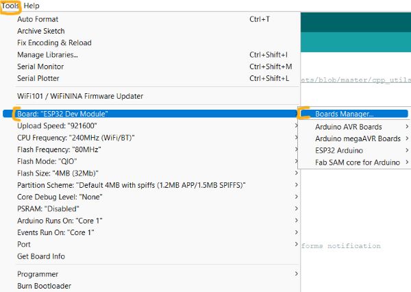
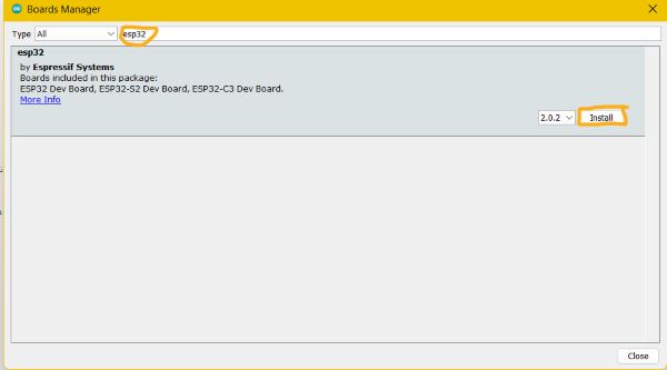
- Go to “Tools” > “Board” > “Boards manager” and search for “esp32” and then download it !
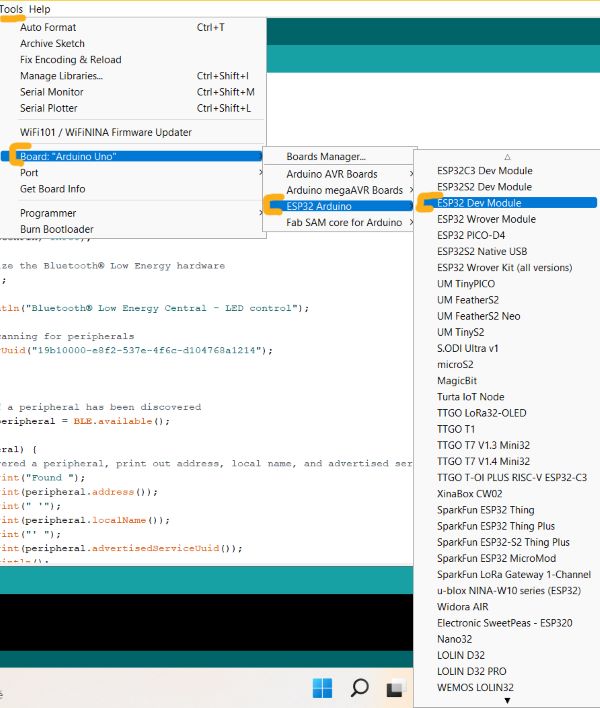
- Then go to “Tools” > “Board” > “ESP32 Arduino” > “ESP32 Dev Module”
- Select the port where your ESP32 is plugged
- Choose an ESP32 example from the library and test it !
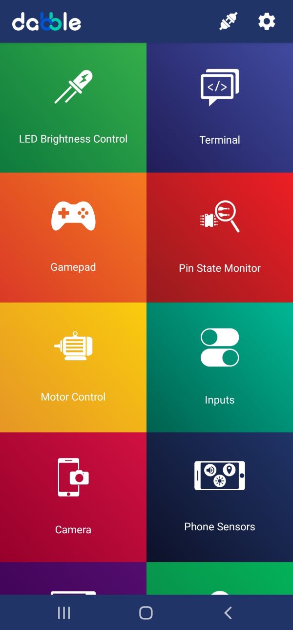
Blink and ledbrightness coding thanks to Dabble
- Download the Dabble Arduino library
- Download the Dabble mobile app
- Open the Dabble library examples
- Open the Dabble mobile application :
Blink example for ESP32
int led = 2;
// the setup function runs once when you press reset or power the board
void setup() {
  // initialize digital pin LED_BUILTIN as an output.
  pinMode(led, OUTPUT);
}

// the loop function runs over and over again forever
void loop() {
  digitalWrite(led, HIGH);   // turn the LED on (HIGH is the voltage level)
  delay(1000);                       // wait for a second
  digitalWrite(led, LOW);    // turn the LED off by making the voltage LOW
  delay(1000);                       // wait for a second
}
Ledbrightness control example for ESP32
/*
   This is Led brightness control example for ESP32 that uses LED Brightness Control Module in Dabble app.
   This module allows you to control state of pin. You can make pin HIGH or LOW or can also assign any PWM
   value to it.

   NOTE: As in esp32 any channel can be configured as a PWM channel hence any first eight pins controlled by Module
   will be treated as PWM and others will be treated as normal digital pins.


   You can reduce the size of library compiled by enabling only those modules that you want to
   use.For this first define CUSTOM_SETTINGS followed by defining INCLUDE_modulename.

   Explore more on: https://thestempedia.com/docs/dabble/getting-started-with-dabble/
*/
#define CUSTOM_SETTINGS
#define INCLUDE_LEDCONTROL_MODULE
#include <DabbleESP32.h>
unsigned long lasttime=0;
void setup() {
  Serial.begin(115200);     // make sure your Serial Monitor is also set at this baud rate.
  Dabble.begin("MyEsp32");     //set bluetooth name of your device
}

void loop() {
  Dabble.processInput();    //this function is used to refresh data obtained from smartphone.Hence calling this function is mandatory in order to get data properly from your mobile.
  //uncomment if you want to check if paramters read correctly
  /*Serial.print("Led:");
  Serial.print(LedControl.getpinNumber());
  Serial.print('\t');
  Serial.print("State:");          //0 if led is Off. 1 if led is On.
  Serial.print(LedControl.getpinState());
  Serial.print('\t');
  Serial.print("Brightness:");
  Serial.println(LedControl.readBrightness());*/
}
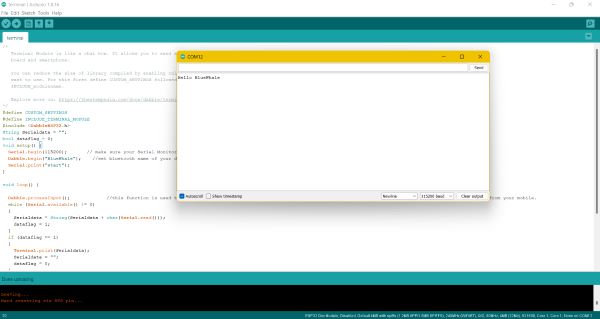
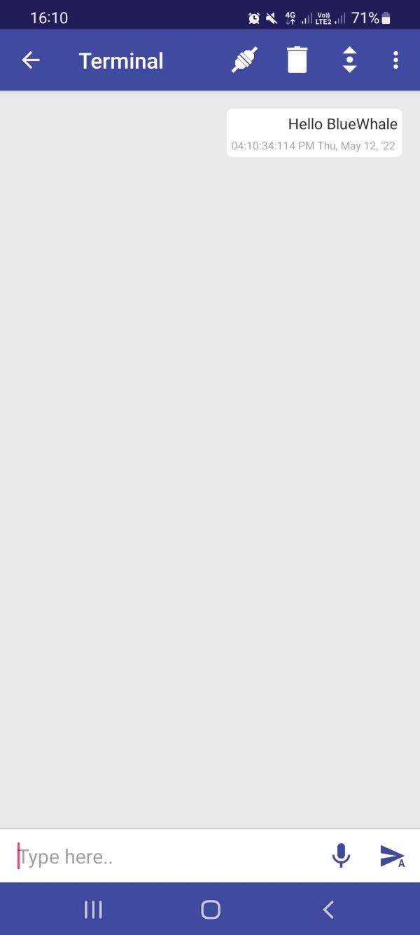
Communicating from your phone to your monitor thanks to Dabble
/*
   Terminal Module is like a chat box. It allows you to send and receive commands between your
   board and smartphone.

   You can reduce the size of library compiled by enabling only those modules that you
   want to use. For this first define CUSTOM_SETTINGS followed by defining
   INCLUDE_modulename.

   Explore more on: https://thestempedia.com/docs/dabble/terminal-module/
*/
#define CUSTOM_SETTINGS
#define INCLUDE_TERMINAL_MODULE
#include <DabbleESP32.h>
String Serialdata = "";
bool dataflag = 0;
void setup() {
  Serial.begin(115200);       // make sure your Serial Monitor is also set at this baud rate.
  Dabble.begin("MyEsp32");    //set bluetooth name of your device
}

void loop() {

  Dabble.processInput();             //this function is used to refresh data obtained from smartphone.Hence calling this function is mandatory in order to get data properly from your mobile.
  while (Serial.available() != 0)
  {
    Serialdata = String(Serialdata + char(Serial.read()));
    dataflag = 1;
  }
  if (dataflag == 1)
  {
    Terminal.print(Serialdata);
    Serialdata = "";
    dataflag = 0;
  }
  if (Terminal.available() != 0)
  {
    while (Terminal.available() != 0)
    {
      Serial.write(Terminal.read());
    }
    Serial.println();
  }
}
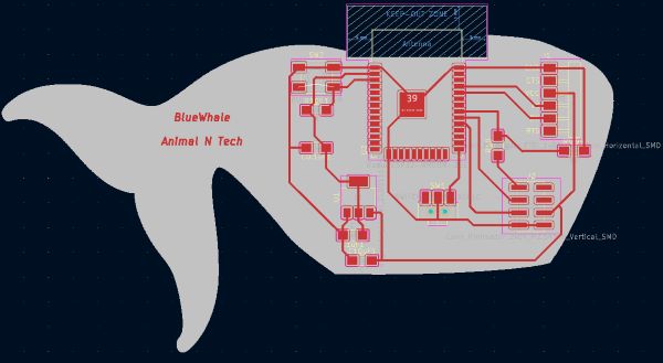
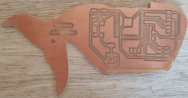
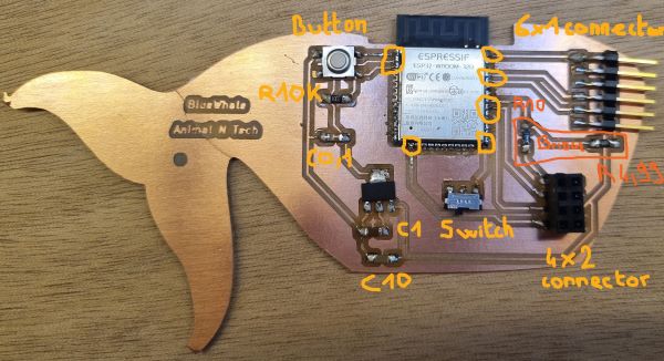
Designing a board with ESP32 module and a Load cell input!
Final design result :
- Open Kicad
- Get inspired with this Neil ESP32 Wroom board example :
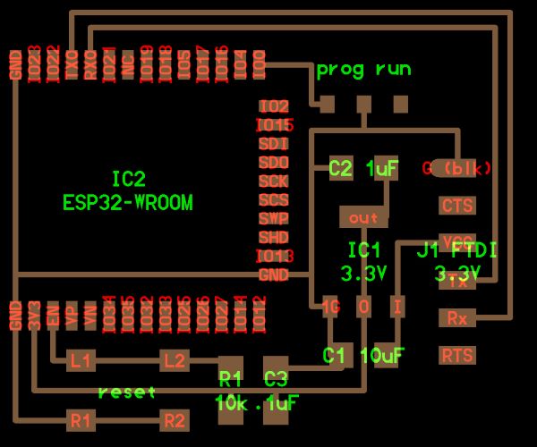
- Place your components regarding your input needs
- Be carefull of the Divider tension bridge needed for the Input
- Divider tension bridge calculator
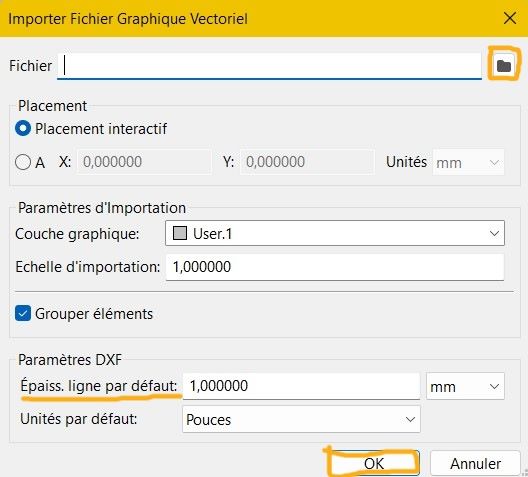
- Add an svg whale file for the shape !
-
Here is the board in progress :
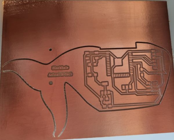
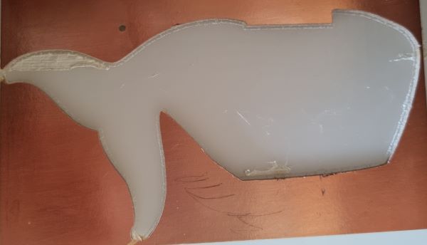
-
Soldering the components : You don’t need to solder all the ESP32 Wroom pins, you just have to solder the connected pins and some others to stabilised the ESP32 on your board !
- Flashing it : remember to switch to the right and press the reset button before flashing with the Arduino IDE and then switch back to the left when it’s done.
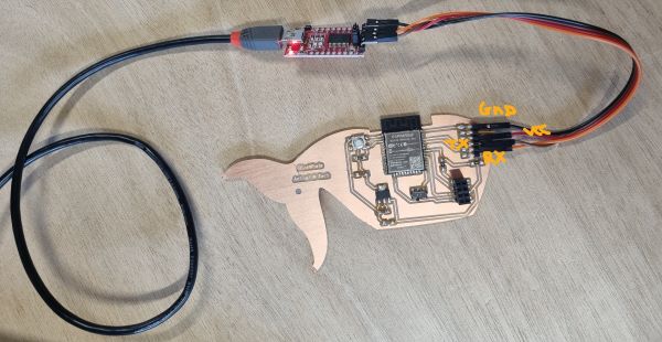
- Testing it by using the Dabble Terminal example :
Communication between a ESP32 and a SAMD11C (homemade board)
We did a communication between a SAMD11C I made at the 5th week and a ESP32 Theo Gautier did !
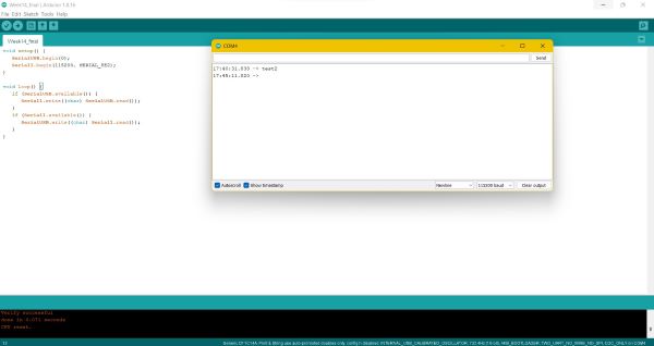
The code is there coming from the Agrilab 2021 group page inspired by the Quentin Bolsee work :
void setup() {
   SerialUSB.begin(0);
   Serial1.begin(115200, SERIAL_8E2);
}

void loop() {
   if (SerialUSB.available()) {
      Serial1.write((char) SerialUSB.read());
   }
   if (Serial1.available()) {
      SerialUSB.write((char) Serial1.read());
   }
}
It allows the two boards to communicate thanks to the RX and TX of each boards that are connected by wires.
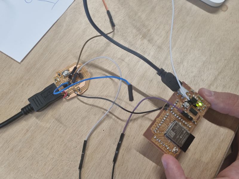
This serial communication allows us to send a message to the other board monitor by writing the message on our monitor :
Problems
My phone (Samsung) wasn’t working with Dabble at the first time we used it with the Arduino board so we used another phone (Fairphone) and it worked. Later, I used Dabble with my own board and then it worked with my phone. I switch off and on my phone to help.
Conclusion
I learned about ESP32 and BLuetooth this week but I still have many things to learn. It’s quite complex and there is a specific vocabulary attached to that like : Clock, CPU, I2C, HCI, SDIO, SPI, UART, RTC watchdog, GATT, API… I need to read more about it.
I also understood that bluetooth consumes a lot a of energy and that there are ways to improve the battery consumption by making some settings that I don’t handle yet but the Bluetooth Low Energy is one way I should deepen.
Files
Useful links
- ESP32 Wroom Datasheet
- ESP32-D0WDQ6 chip
- ESP32 Arduino IDE Board Manager URL
- ESP32 Arduino IDE tutorial
- Dabble
- Divider tension bridge calculator
- Diviser tension bridge explanations
- Neil ESP32 Wroom board
- input needs
- Source Android