3. Computer Aided design
This week I worked on 2D and 3D modeling my final project with : Inkscape, Paint (2D), Autodesk Fusion 360 and Blender (3D)
2D modeling with Inkscape
Design thinking
The first step was to think about the design of the product regarding its use. As I want it to measure the force exerted on the dog leash, it needs to be placed where the force sensor can work. I get inspired by a horse rein tensionmeter called EC-Hand Tensiometer that I saw on the website “epplejeck”. The force sensor needs to be in contact with its 2 ends to the leash to measure the tractive force as in the “EC-Hand Tensionmeter” below. I’ve annoted the different strengths in orange with windows 11 image tool that allows to annoted the picture with the computer touchpad.
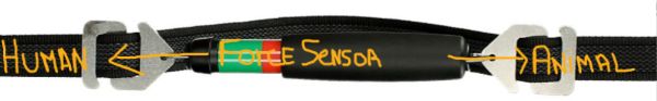
Image modified from the site Epplejeck presenting the EC-Hand Tensiometer
Then I checked a dog leash product to amortize the impacts of dog pulling on leash, called Yangbaga that I saw on “Amazon” and annoted with orange.
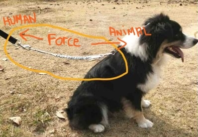
Image modified from the site Amazon presenting the Yangbaga anti-shock leash
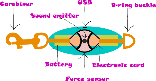
It gave me the idea with the advices of my instructors to put the electronic tensiometer at the base of the leash to adapt with the collar or the harness and so be in capacity to measure the strength exerced on the leash. As figured on the picture below :

It means that there will be a carabiner at the collar/harness side and a stainless metal d-ring on the leash side.
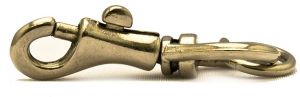
Carabiner from pixabay
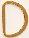
D-ring buckle from Joyce Trimming Inc
Now that I know better how will look my connected object, I can start the work of 2D modeling.
Inkscape
The final result :
The different steps :
-
Download Inkscape
-
Open Inkscape
-
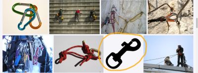
Download a carabiner picture from pixabay
-
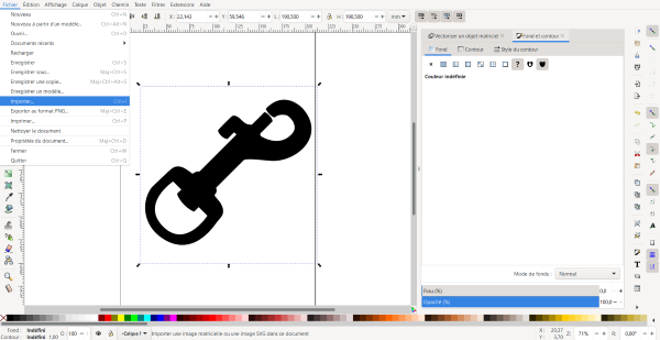
Import the picture to Inkscape
-
Make a rotation of the image with “ctrl” and “[“
- Create an ellipse
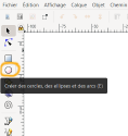
- Create 2 circles
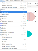
- Select the 2 circles and click on “path” > “difference” => a new form is created
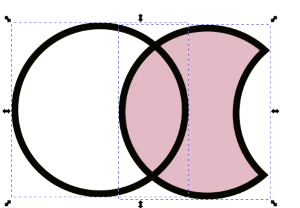
- Create another circle and do it again to finish the form

- Create 2 triangles and move it to the new form

- Remove the background of the triangle with the menu on the right
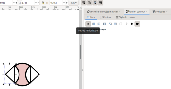
- Select the 2 empty triangles and the form and click on “object” > “group” => all the select elements are now one unique piece
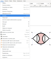
- Move it on the ellipse, click on the left menu on “edit nodes” and move the right side on of the triangle to follow the shape of the curve
- Which leads to that :

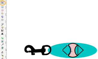
- Then add rectangles, create the D form with the Bezier curves, add circles and change the color with the menu on the right

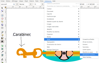
- Finally, add some text by clicking on “extensions” > text > replace the font
Paint
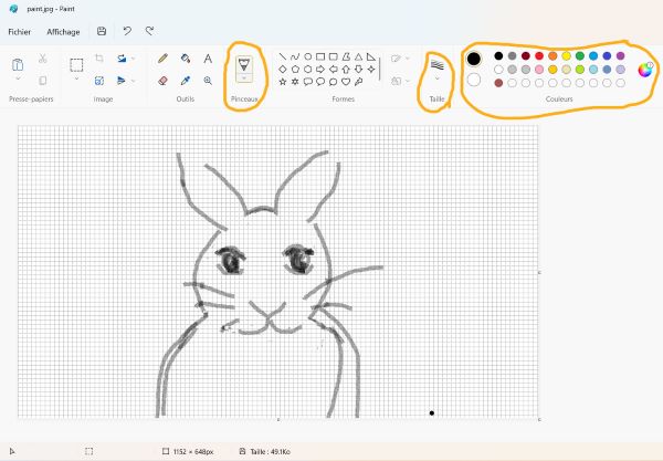
I did a rabbit sketch on Paint.
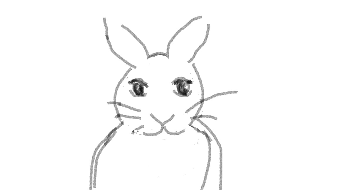
I modified the type of pencil, the size and the color :
3D modeling with Autodesk Fusion 360 and Blender
Autodesk Fusion 360
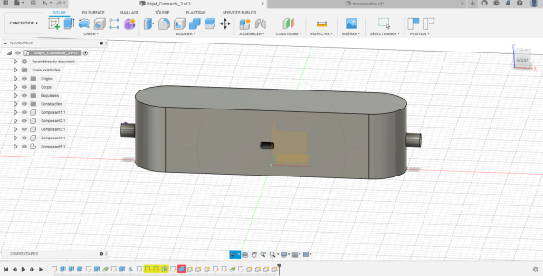
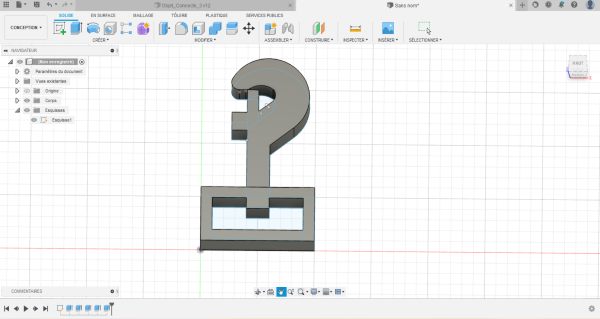
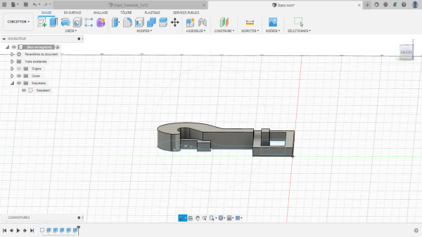
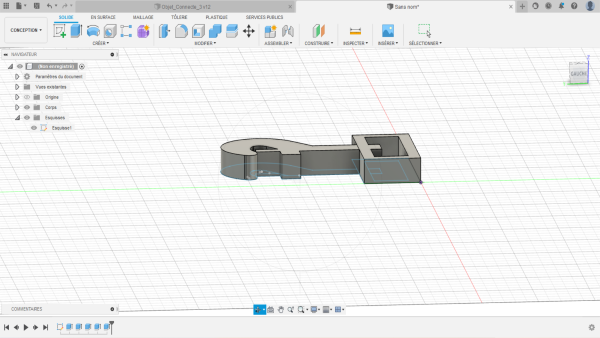
I drew the outer box of my connected object and a carabiner that would go on the box.
Final results :
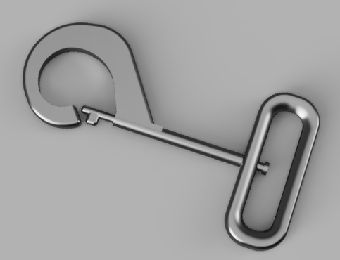
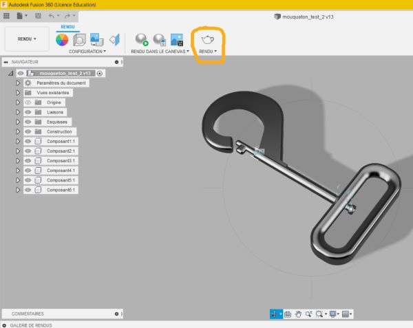
That’s the render of the improved carabiner :
- Download Fusion
- Open Fusion
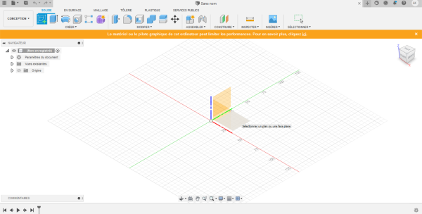
- Click on sketch
- Choose a plan
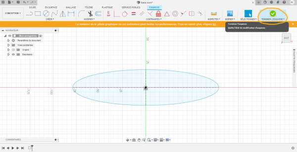
- Click on created and choose ellipse

- Centered the ellipse, design it and click on “finished the sketch”
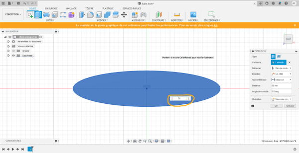
- Click on extrusion to add volume
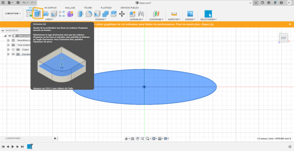
- Enter a positive value if you want to add volume an a negative value if you want to remove volume
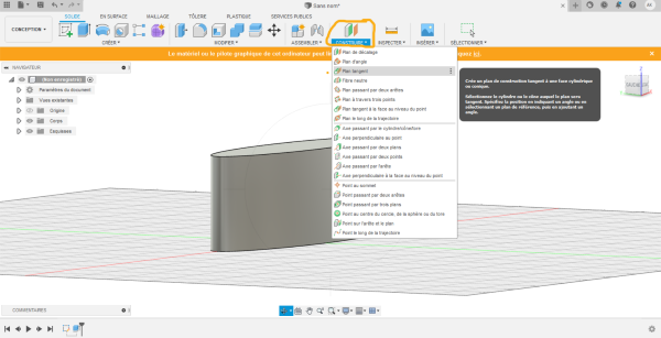
- Add a tangent plan to the ellipse by clicking on “build” > “Add tangent plan” (but it didn’t work so I aborted this shape)
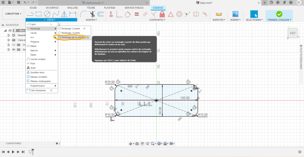
- Design a rectangle by clicking on “sketch” > “choose plan” > “created” > “rectangle” > “rectangle by the center” and then rounded corners with the tool surrounded with orange
-
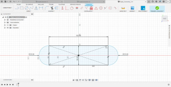
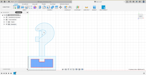
As I didn’t like the shape I started again a new sketch by forming a rectangle with 2 semicircles formed with the “arc” tool in “created”
-
Then Define the width at 50 mm and the length at 150 mm
-
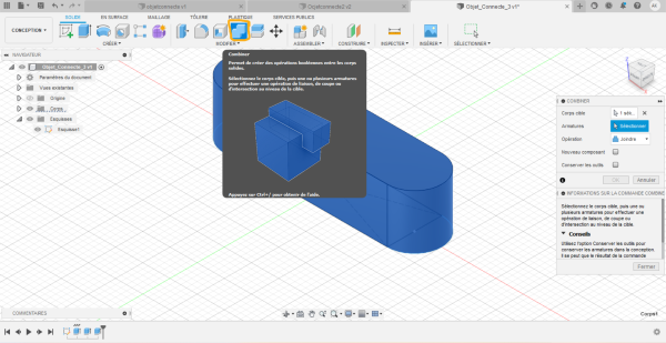
Define the height : 50 mm with the extrusion tool
-
Make the old sketch visible by clicking on the crossed eye on the left menu and select the all to click on “combine” to make it one
-
Make a circle on a face and then make a negative extrusion to make a hole for the USB port
-
Add 2 tangent plans at the extremities and create two circles
-
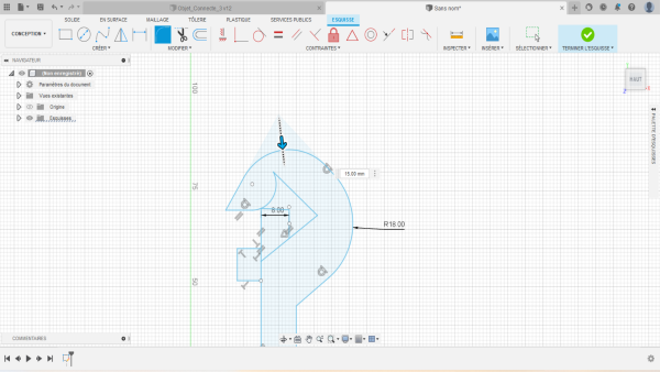
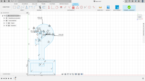
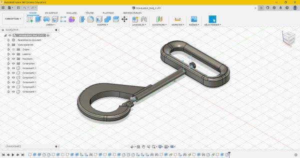
Then I did a carabiner
- First : create a sketch with the “line” tool and design all the carabiner
- Then : make a curve with the filet tool and play with the different angles to get those you want
-
Make an extrusion of the parts you want
-
Make sure you put the same size
-
And that’s all !
For the improved carabiner more steps were needed. The piece was made with different sketchs that were then merged.
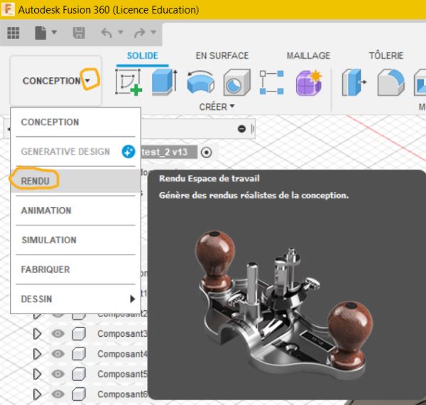
Render
Go to the render mode :
Move your object until you get a nice plan and click on “render” :
Animation
Here is my carabiner animation :
I did it with the animation function in Autodesk fusion 360.
- Create a scenario
- Select the components you want to make move
- Transform it with the moves/ rotations you want
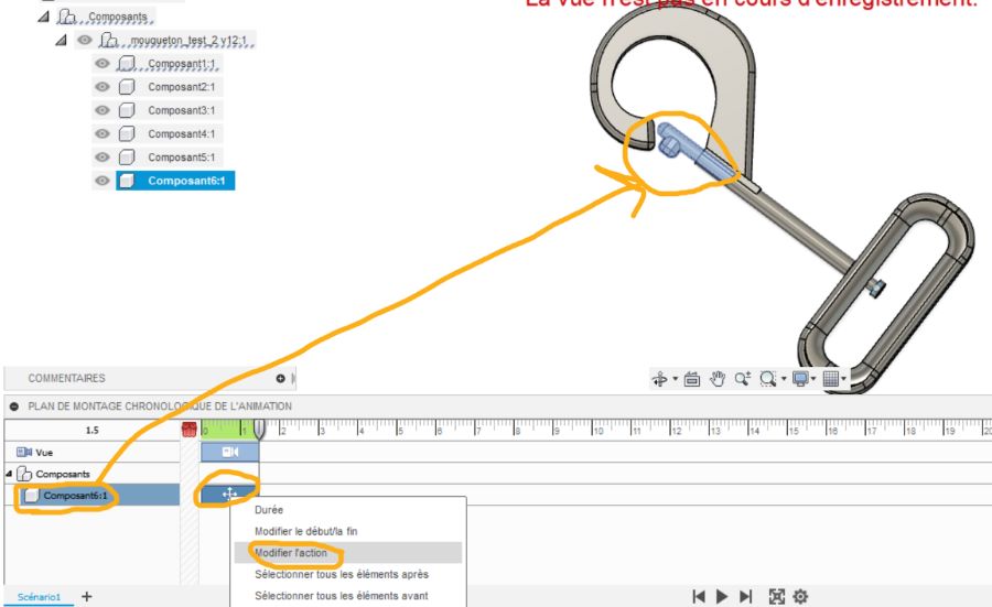
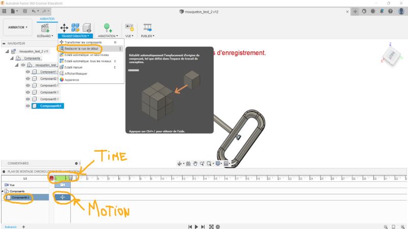
- Change the timing or the order of the moves as you want
- You can also make it ends as it began by clicking on “transformation” > “restore the view to the beginning”
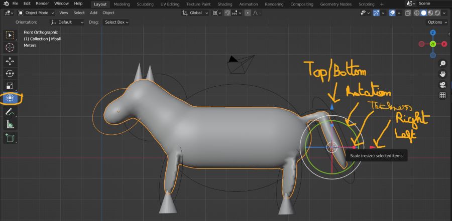
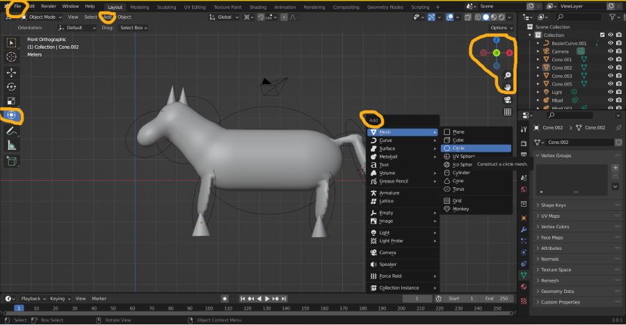
Blender
- Download Blender
- Open Blender
- Delete the cube by selecting it and press “delete” on your computer
- Click on “shift” + “a” to add a new form
- Move your new form by clicking on it and then click on the “transform” button on the left and then move the different circles and cursors to make it bigger/smaller or just move it
- You can zoom with your touchpad or by clicking on the “+” button on blender screen
- If you want the shape to merge you need to move it very close and a merge should be created automatically
- If you want to change the plan, you can click on the different “x”, “y”, “z” axis at the right of your screen
Files
I added my files by exporting it from Autodesk Fusion 360 to : “git > site > docs > files” :
- Carabiner with Autodesk Fusion 360 (.f3d)
- Box with Autodesk Fusion 360 (.f3d)
- Carabiner improved with Autodesk fusion 360 (.f3d)
- Horse with Blender (.stl)