9. Embedded programming
This week I worked on embedded programming. The assignments are below :
Reading the ATSAMD11C Datasheet
I used the Atmel SMART SAMD11 with 14 pins wich is a low-power microcontroller noted ATSAMD11C 14 pin - SOIC Open its datasheet and browse the table of content to have a global view :
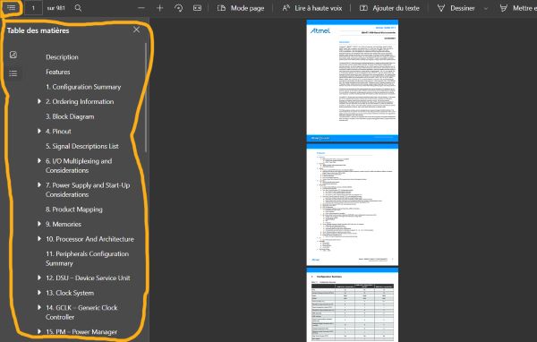
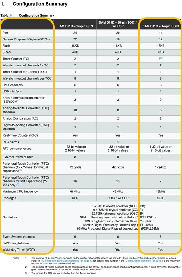
Then check the different parameters of your microcontroller on the configuration summary.
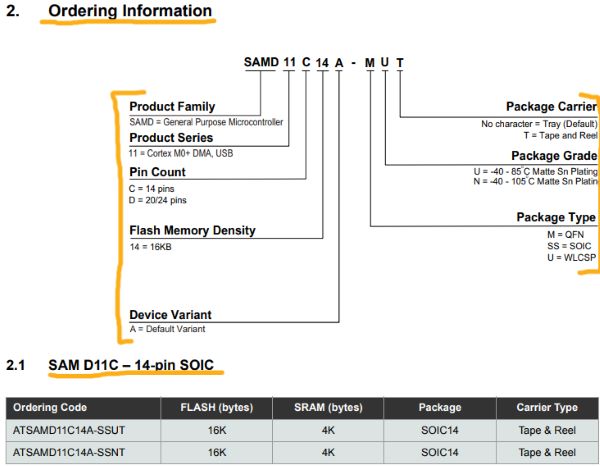
Here is some ordering informations about SAMD11C14 and the meaning of the letters in the name :
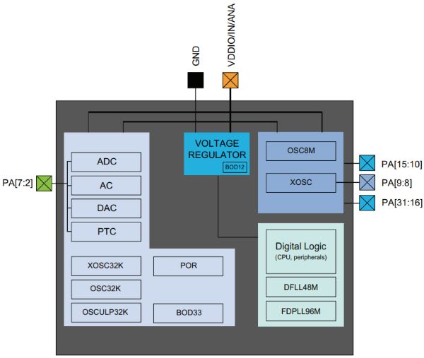
Now an important information : the Block Diagram

Pinout organisation :
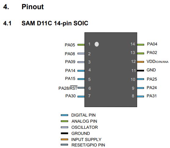
- Digital pin are used for the binary values like : “HIGH”/”LOW”
- Analog pin are used for the variable values like : “0”, “3,5”, “50”
There are 12 General Purpose I/O-pins (GPIOs) to connect the board with the input (to receive the data) and the output (to deliver the data).
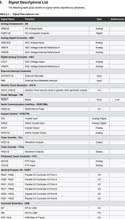
Signal Description list
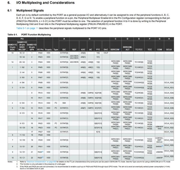
Port Function Multiplexing
Power domain overview
Attention
The power supported by the microcontroler is between 1.62 and 3.63V ! It means that you need to put some condensator and regulator to adapt the power if you put it on your computer usb port that is around 5.5V.
Programming my board to do something
With Arduino IDE
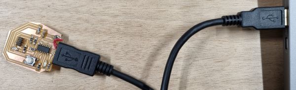
Connect your board to your computer with a USB cable :
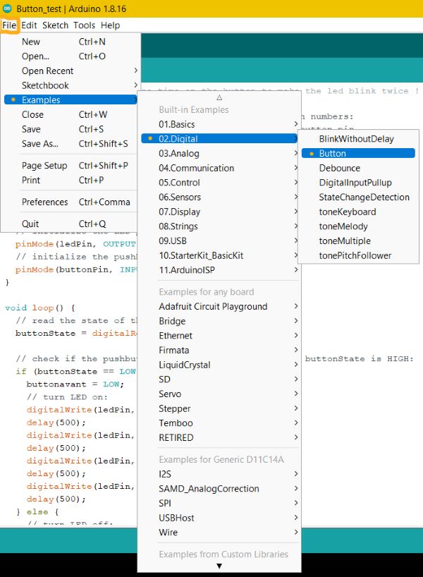
- Open the Arduino IDE
- Select your board
- Select the port of your board on your computer
- Open the Button example
- Modify it :
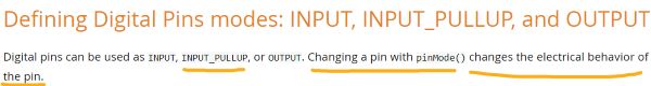
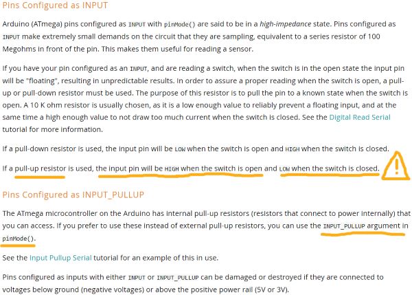
As my button is in the pull up mode I have to inverse the “LOW” and “HIGH” functions because it’s doing the opposite as explained below :
- Go to Arduino Documentation, click on “Reference” and scroll down to “Variables” :
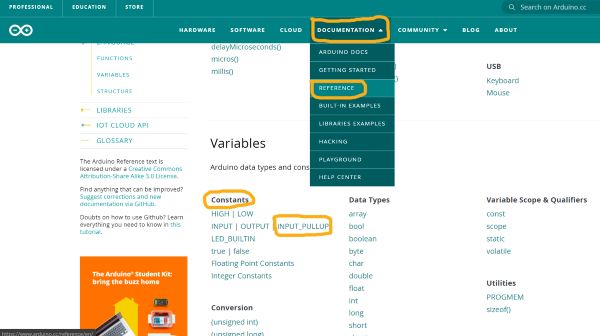
- Then click on “INPUT_PULLUP” and read the documentation :
/*Aurore KUBICA : press one time on the button to make the led blink twice ! */

// constants won't change. They're used here to set pin numbers:
const int buttonPin = 2;     // the number of the pushbutton pin
const int ledPin =  4;      // the number of the LED pin

// variables will change:
int buttonState = 0;         // variable for reading the pushbutton status
int buttonavant = 0;       // the state of the button before

void setup() {
  // initialize the LED pin as an output:
  pinMode(ledPin, OUTPUT);
  // initialize the pushbutton pin as an input:
  pinMode(buttonPin, INPUT_PULLUP); // I did a Pull up installation for my button on the board so I have to put "INPUT_PULLUP"
}

void loop() {
  // read the state of the pushbutton value:
  buttonState = digitalRead(buttonPin);

  // check if the pushbutton is pressed and if it wasn't pressed before. If so, the buttonState is LOW and the buttonavant is HIGH :
  if (buttonState == LOW && buttonavant==HIGH) { // Use the Boolean operator "&&" "Logical AND" because I want the 2 conditions (buttonState and buttonavant) to be true to realise the "if"
    buttonavant = LOW;
    // turn LED on:
    digitalWrite(ledPin, HIGH);
    delay(500); // wait 500 ms
    // turn LED off :
    digitalWrite(ledPin, LOW);
    delay(500);
    digitalWrite(ledPin, HIGH);
    delay(500);
    digitalWrite(ledPin, LOW);
    delay(500);
  } else {
    // turn LED off:
    digitalWrite(ledPin, LOW);
    buttonavant = buttonState; // Add this line to have only 2 blinks when you press one time the button or it will continue because the loops are very quick.
  }
}
- Click on “upload”
- And it works : the code is flashed on your board SAMD11C microcontroller !
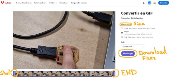
I used ADOBE Express to convert my video to GIF : It’s free you just have to create a count.
- First put your video : drop it or browse it

- Then select the beginning and the end of your gif, choose the size and download it !
With Visual Studio Code
- First download Visual Studio Code
- Open it, click on “Extensions” and search for “platformio IDE” and then click on “install”
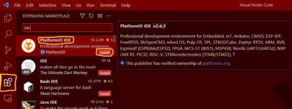
- Then click on “PlatformIO” represented by a strange alien face, click on “Projects & Configuration” and click on “Create New Project”
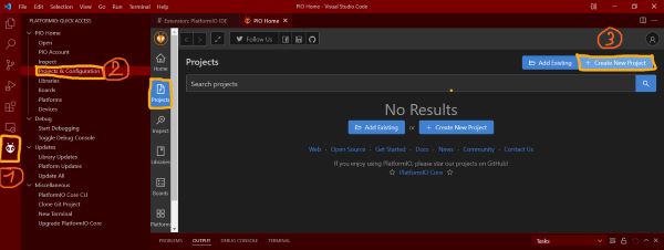
- You can have some help by following the Visual Studio Code Platformio Quick Start
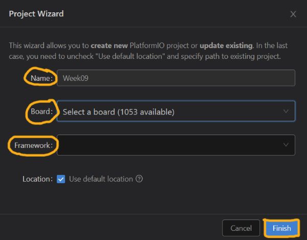
- Create a new project by entering its name, the board you use and the framework :
Group Assignment :
Comparaison of the ATSAMD11C Datasheet and the ESP32 Wroom D0WDQ6 Datasheet
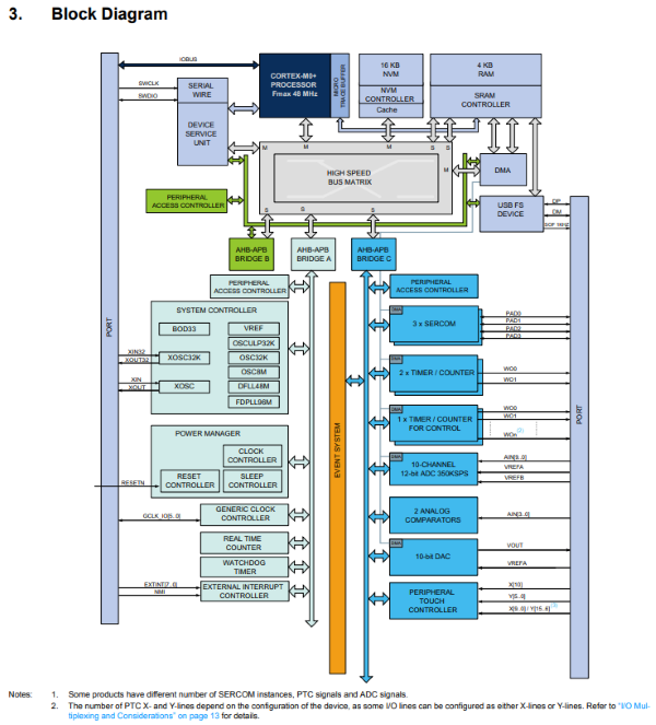
ATSAMD11C Block Diagram

ESP32 Block Diagram
The ESP32 is different of the ATSAMD11C because it has the bluetooth and wifi functions that are accompanied with specifics functions like :
- 2.4GHz Wi-Fi and Bluetooth combo chip, TSMC ultra Low-Power 40nm technology (fine-grained clock gating, multiple power modes, and dynamic power scaling),
- 2 CPU cores that can be individually controlled. The CPU clock frequency is adjustable from 80MHz to 240Mhz. The CPU can be powered off by the user and the low-power processor can be used to monitor the peripherals for changes or crossing thresholds.
- I2C
- UART
also, the ESP32 has 48 pins whereas the ATSAMD11C14 has 14 ones.
Useful links
- ATSAMD11C Datasheet
- ADOBE Express convert video to GIF
- Arduino IDE
- Arduino Documentation
- Visual Studio Code Platformio Quick Start
- Visual Studio Code
- ESP32 Wroom Datasheet