5. Electronics production
This week I worked on electronics production with a milling machine and a soldering machine to make an in-house PCB (Printed Circuit Board) production. The assignements are below :
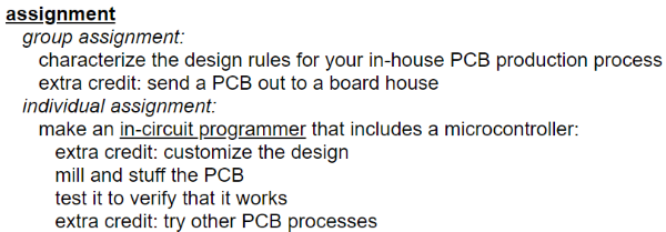
Hero shot
Milling machines
To make a homemade PCB you have to mill a copper plate with a milling machine regarding the circuit (components, traces…) you want.
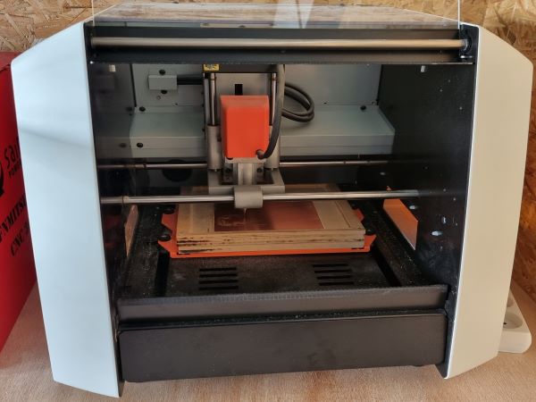
Milling machines description
I used 2 machines :
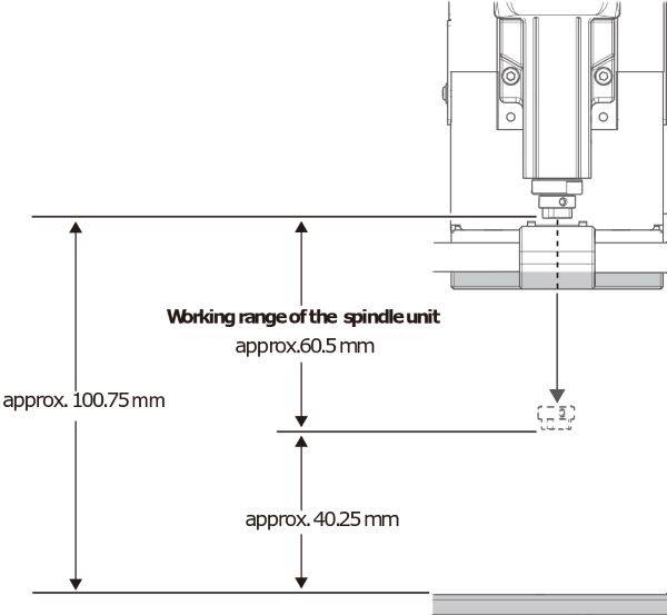
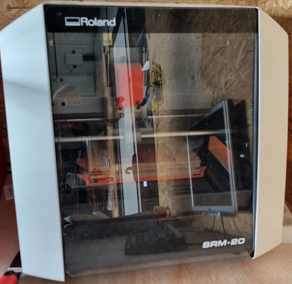
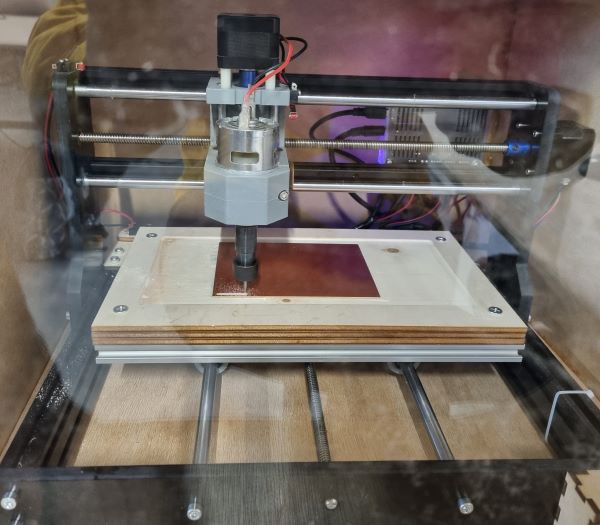
CNC Roland SRM20 working with the software VPanel for SRM-20
Here are the working dimensions :
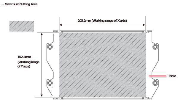
Size of the sacrificial layer :
- Length : 152.40 mm
- Width : 184.75 mm
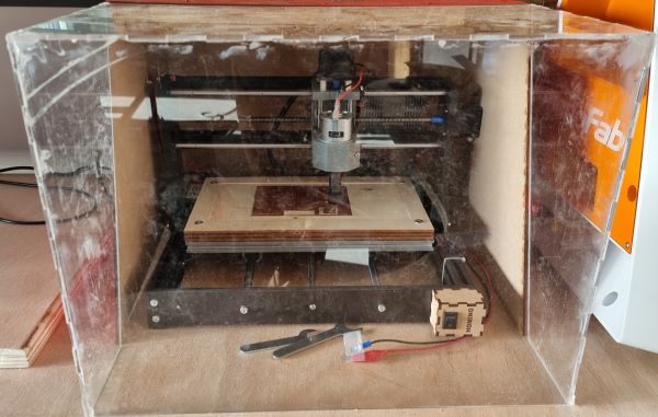
When you use it you have to put down the safety glass :
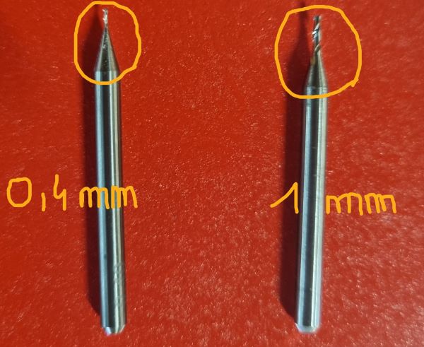
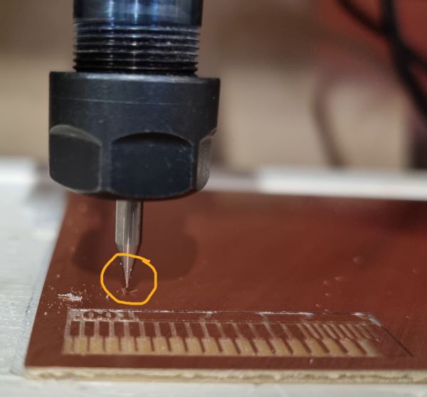
First, choose the milling machine bit :
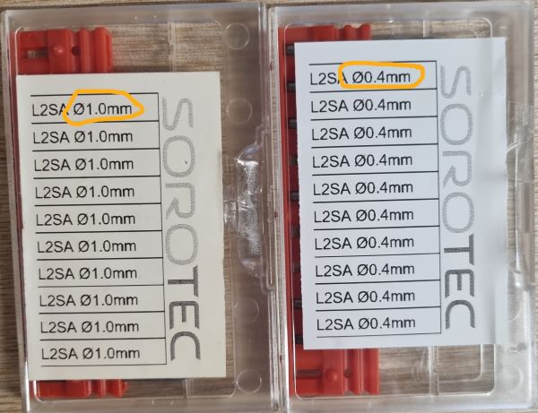
I used the flat end mill 2 flute : 0,4mm for the interior trace and the 1mm for the outer edges
Then, place it on your milling machine by tightening the screw :
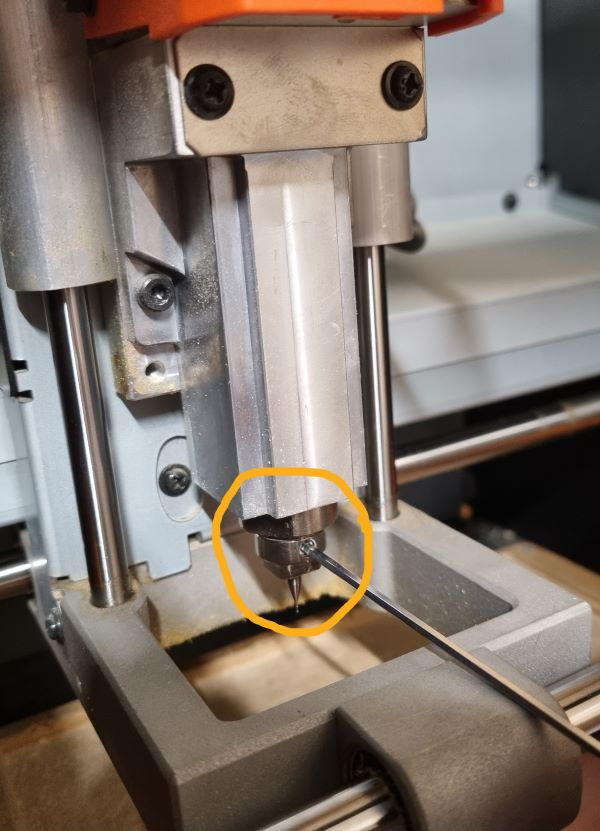
Select the Z and XY origins to orient the machine in space :
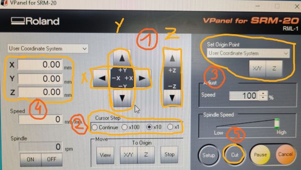
1) Start by choosing the “cursor step” to select the speed you want the cursor to move. Be careful if you are moving the cursor in the Z axis because you could break the milling bit if you’re too fast !
2) Move the cursor to the exact place you want to start on the copper plate with the X, Y and Z axis.
3) Once you find the right place, click on “X/Y” and “Z” to make the Origin. For the “Z”, once you are very close to the plaque you can just unscrew the screw to make a soft contact of the bit with the plaque and then rescrew.
4) Coordinates on the left should be on zero
5) Click on “Cut” to select the file you want to cut
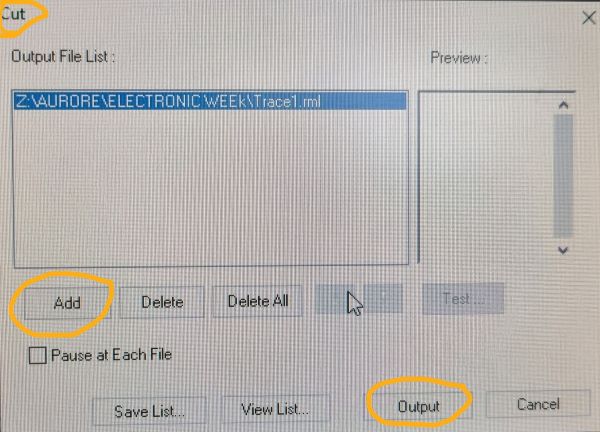
- Delete the old files, if there are
- Click on “Add” to select the file
- Click on “Output” to start the cutting !
Sain Smart Genmitsu Routeur CNC 3018 pro working with the software Candle
Working dimensions :
- About 300mm x 180mm
It’s a quite simple machine that you can assemble yourself following the CNC Roland SRM20 manual.
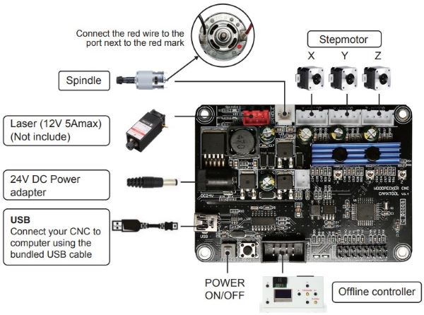
Here are some explanations about the control board installation and the card controlling the machine :
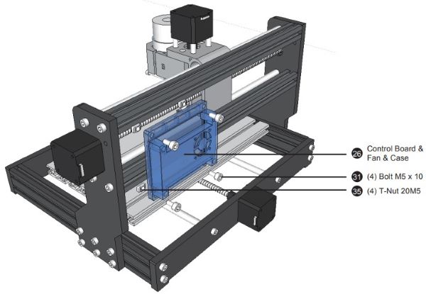
The advantage of this machine is that it has a palpation system that corrects automatically the Z axis to make sure the milling flat doesn’t break.
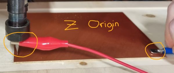
First set the origin point (X,Y,Z) with an electrical probe and a crocodile clip :
Use the software Candle :
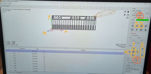
1) Select your “G code” file that you configure in “mods” as explained below
2) Move your axis to choose your origin
3) Click on the X,Y and Z probe buttons to set it up
4) Click on start
Once you understand how works a milling machine you can use an existing file to make a trial as I did with the bootloader working with SAMD11C.
Here are the traces :
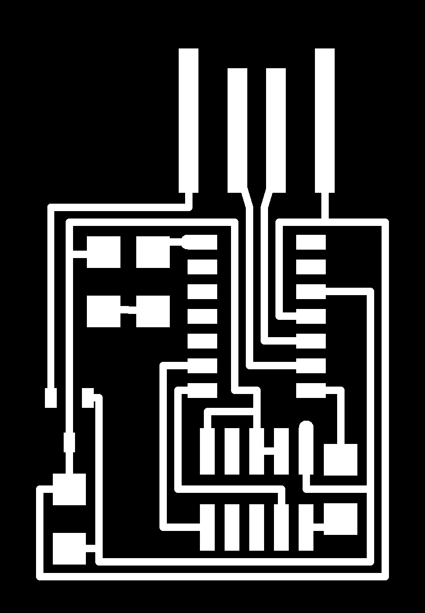 And the interior :

The next part explains how to turn the png file of your board into a file working with the CNC. It can be a “g.code” file for the CNC18 or a “.rml” file for the Roland. I used mods because it’s the FabAcademy recommended solution proposed.
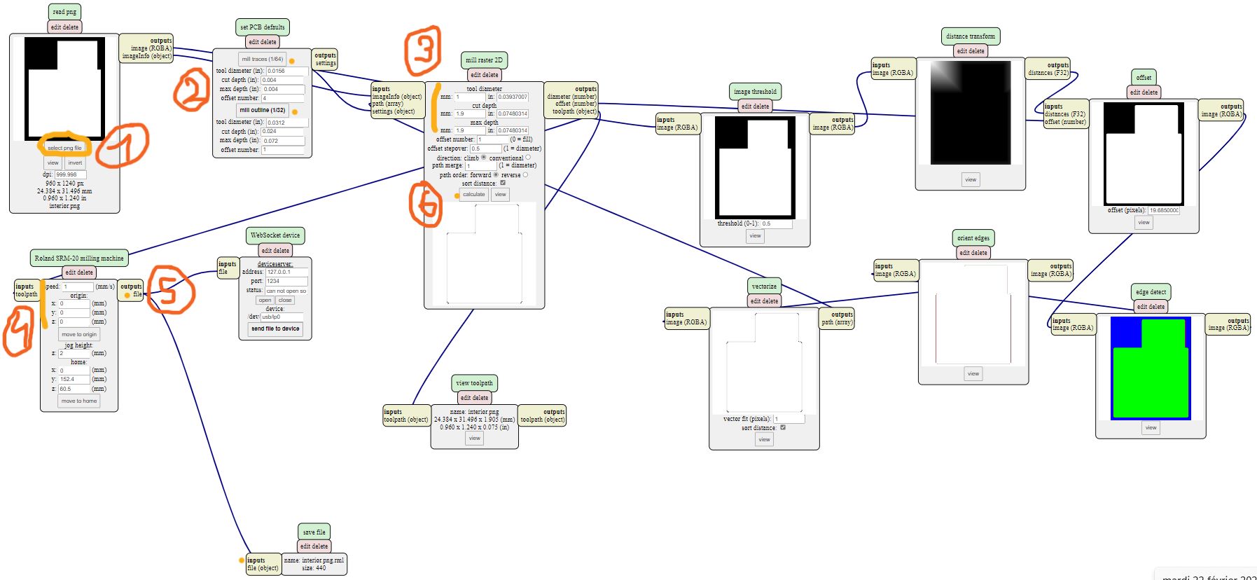
Preparation of the file for the milling machine with mods
- Use the software mods
1) Make a right click, select “programs” > “open server programm” > select “G code” for the CNC 3018 and “Roland” for the CNC Roland > select the “png” file regardind your extension file.
2) Select your png file
3) Select “mill trace” if you’re doing the intern trace or “mill outline” if you’re cutting the outer edges
4) Set you parameters : “tool diameter” (your mill diameter), “cut depth” (how deep you want to go) and “max depth”
5) Choose your speed regarding the work you want to do. (for a smaller mill we reduce the speed to make sure it doesn’t break)
6) Add the saving module by making a right click and selecting “modules” > “server module” > “file” > “save”
7) Then make a link between “outputs file” and “inputs file” by making a left click to save and export the file you just prepared for the machine. Regarding the CNC you’re working with, the format would change : “.rml” for the Roland and “.nc” for the CNC 3018 pro.
8) Finally, click on “calculate” and your file would be download !
- Delete the wrong lines in the Gcode for the Sain Smart Genmitsu Routeur CNC 3018 pro :
- ”%”
- “T1mo6”
- “G04P1000”
Group work with Theo Gautier from Agrilab
The aim was to determined the cutting limits of the machine. We used the CNC 3018 pro because we met an issue with the Roland.
- First set the parameters with mods and launch it
- The mill broke we had to start again and decrease the speed. We started from 1mm/s and finished to 0.16 mm/s.
- We needed 4 trials before succeed : we noticed that with the machine vibration the screws had come loose and it can explain the successive broken mills.
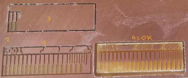
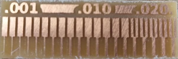
- Final result after cutting the interior trace first and then the outer edge :
- As we met an issue with the Roland machine for this test, we compared the final cutting (on the left) with the test of last year realised with the CNC Roland (on the right) :
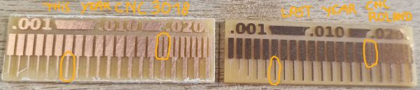
We observed that regarding the machine, the precision and the limits of cutting are not the same. The Roland is more precised as we can see on the picture. It can cut a trace even at 0.10 inches whereas the CNC 3018 can start at 0.13 inches. Thus, if you want to work more precisly with some smaller traces, the CNC Roland is the one you need but if you want to work beyond 0.13 inches, you can use the CNC 3018 !
Cutting parameters
For the cut depth, put the half of your mill diameter to improve your success chances !
Outline parameters :
| Speed (mm/s) | Mill diameter (mm) | Cut depth (mm) | Max depth (mm) |
|---|---|---|---|
| 1 | 1 | 0.5 | 1.9 |
Trace parameters :
| Speed (mm/s) | Mill diameter (mm) | Cut depth (mm) | Max depth (mm) |
|---|---|---|---|
| 0.8 | 0.4 | 0.08 | 0.08 |
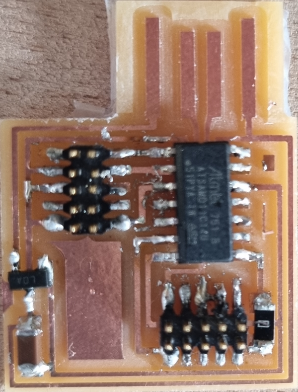
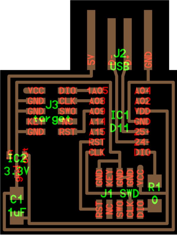
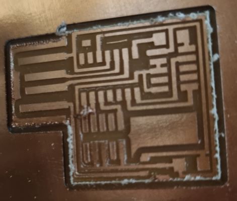
PCB Production
The aim was to make this :
- First set it on mods
- Install the copper plate on the middle of the sacrificial layer by putting some double-sided adhesive tape
- Send it to the Roland with the software “VPanel” and set it up with the X/Y and Z origin
- Start with the interior trace and then do the outline
- Take care when you take off the final pcb of your copper plaque
- Clean it with water
- Now you can start soldering !
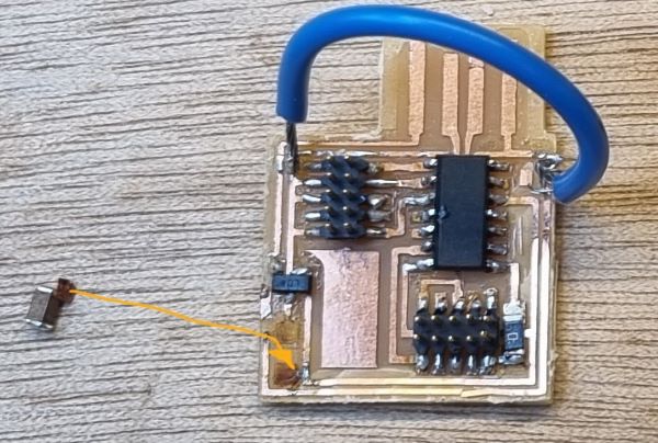
Soldering
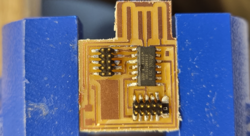
Here is the list of all the components I soldered :
- 1 x ATMEL ATSAMD11C14U
- 1 x 0 Ohme Resistor
- 2 x 10 male connectors
Then Install your work environment :
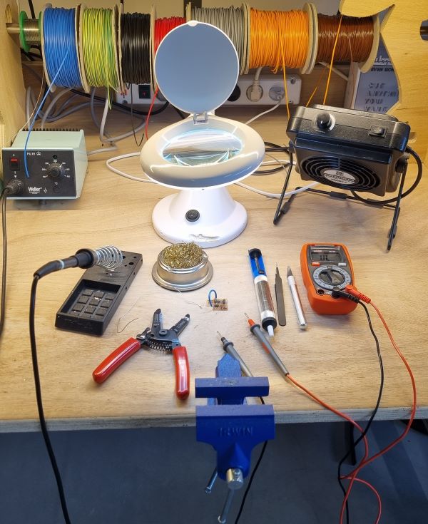
- Fix the pcb to make it stable when you’re soldering
- And start by soldering the smaller and internal components because it would be complicated after and the chance of soldering together two pieces that should not would improve if so…
- If you miss a solder, you can revert it by using a tool that aspires the melting tin
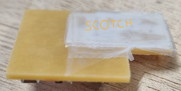
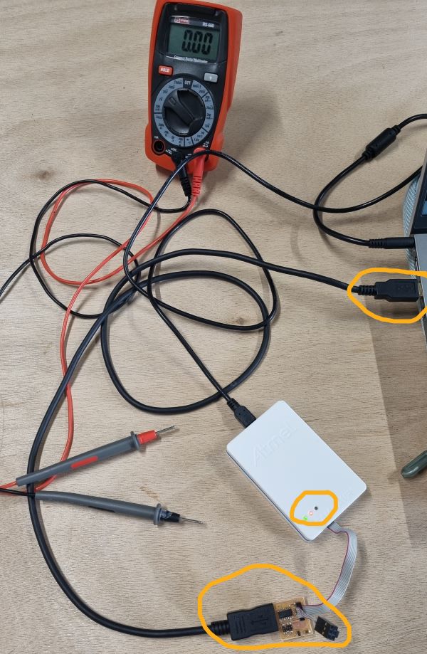
Flashing your microcontroller
- Add some adhesive tape to make your USB port thicker to improve the contact with your computer port
- Download the software Microship studio
- Download some files : EDBG File and Free Dap file
- Go to your computer invite and write this line :
edbg -b -t samd11 -pv -f free_dap_d11c_mini.bin
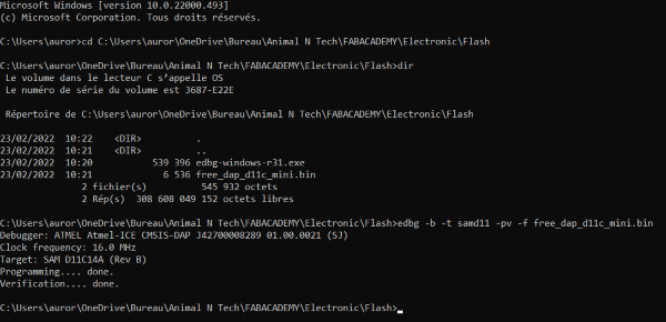
- Then flash it :
Week feelings
It was a very instructive week with a lot of new challenging knowledges ! It’s very helpful for the next electronic weeks and for my final connected object project.
Mistakes
- Broken mills (wrong cutting parameters, wrong manipulation)
- Wrong solder (touching two copper traces that should not)
Visit to another lab
We went to another lab in Amiens to see different ways of making a PCB like with a laser or a chemical way.
Useful links
- CNC Roland SRM20
- VPanel
- Sain Smart Genmitsu Routeur CNC 3018 pro working with the software Candle
- Candle
- Microship studio
- EDBG File
- Agrilab
- Agrilab machines documentation
- CNC Roland SRM20 manual
- bootloader working with SAMD11C
- final connected object project