8. Computer controlled machining
This week I worked on Computer-Controlled Machining. The assignments are below :
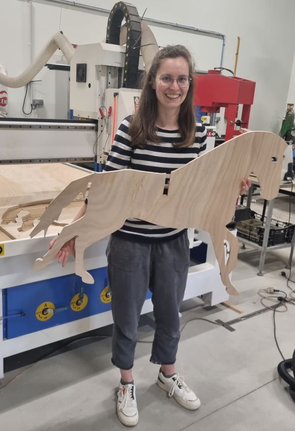
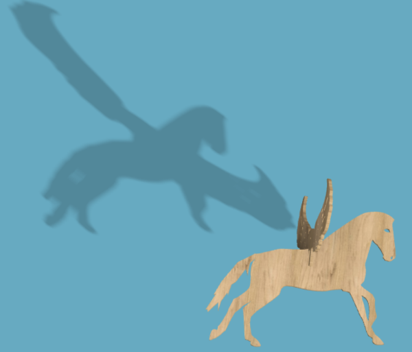
Hero Shot
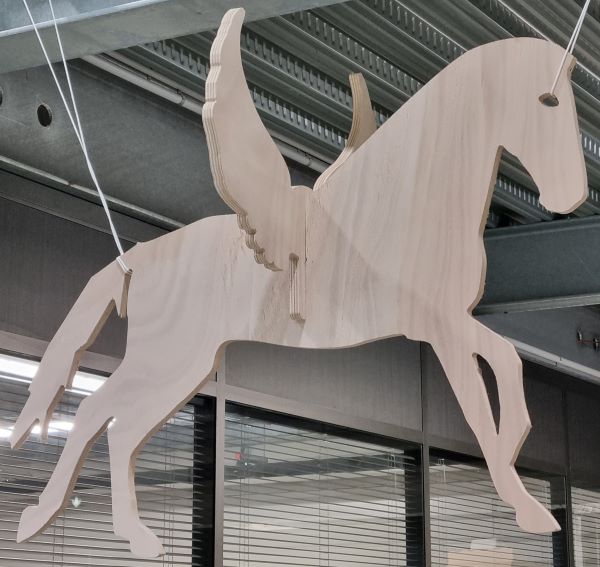
Machine Description
I used the MLLASER CNC.
It’s a Large 3-axis CNC router with cylinder turner, tool changer and vacuum table.
The Machineable dimensions are : 1500mm * 2400 mm * thickness depending on other parameters (martyrdom, cutter length,…).
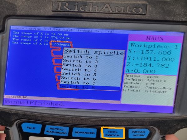
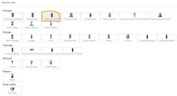
There are 8 differents tools.
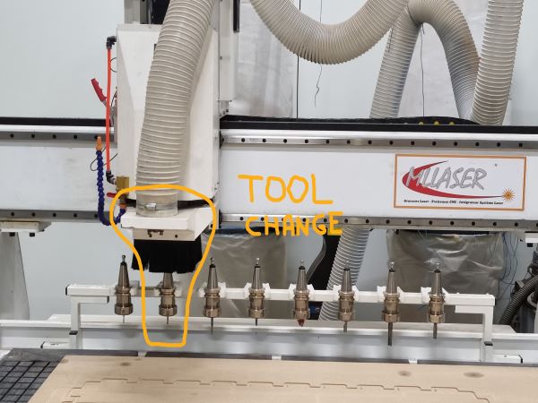
To change the tool, you have to use the remote control and click on “tool switch” and then choose the tool you need :
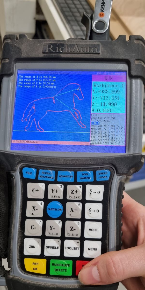
You also have a Wood chip suction and an oil bath circuit for metal cutting. The remote control allows you to set the X,Y,Z zero. Move the head of the machine where you want and click on “X/Y” to set the X/Y origin on your material.
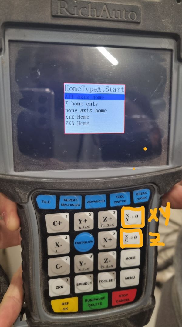
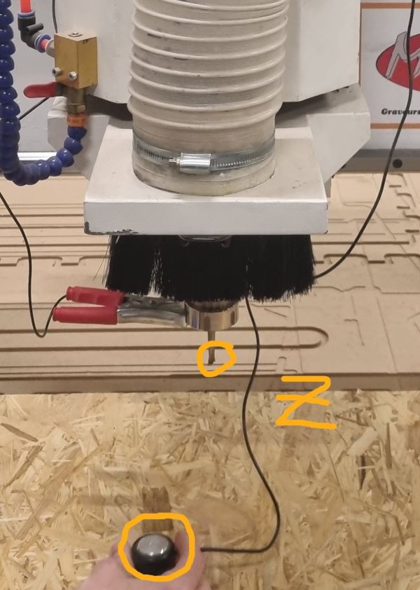
“The XY->0 fixed the G54 home in X and Y The ZC->0 fixed the G54 home in Z.” and “The Toolset is an automatic Z , you have to use an electric sensor that measure the contact between the spindle and the sensor. It’s a precise way to determine the Z.”
You have to fix the material you want to mill with screws to make sure it doesn’t move during the process. The machine is also equipped with a depression table to help maintaining the material.
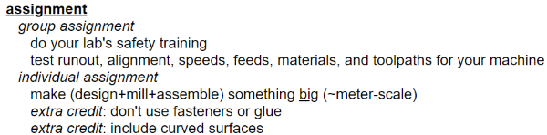
Designing a Horse with wings
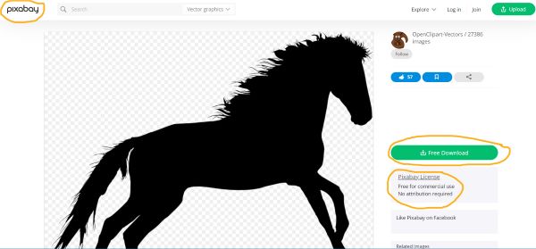
I chose a vector graphic picture of a horse and wings on Pixabay because it’s free and no attribution is required. I download it :
Then I opened Inkscape to see the image, vectorised it, chose the dimensions, simplified the shape so the mill could go between the traces :

and save it as a .svg file.
Preparing the file with Autodesk Fusion 360
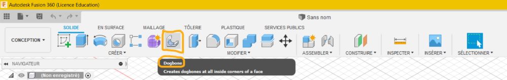
- Download the Dogbone addin for fusion 360

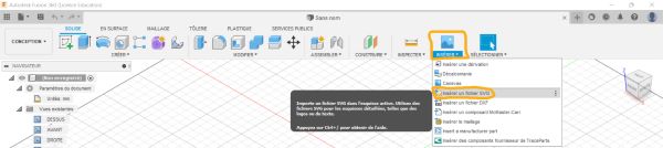
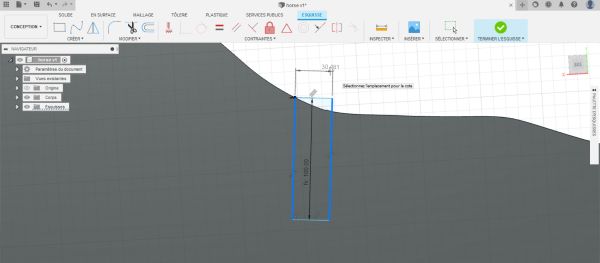
- Insert your “.svg” file :
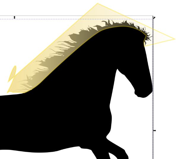
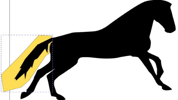
- Add a rectangle to make it possible to add the wings at the back of the horse and other sketch details if you want. Make sure it’s parametric and extrud it regarding the width of your material. You should measure it on the exact piece of material you want to use because it may vary.
- Add the dogbone :
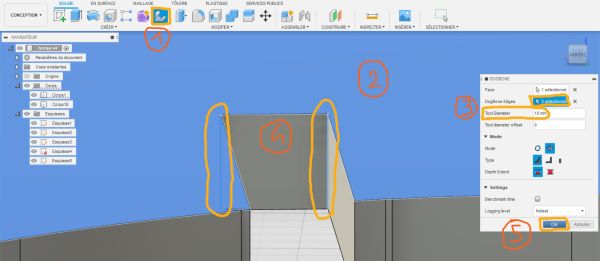
- Click on “dogbone”
- Select the face where you want to add it
- Select the dogbone edges and set your “Tool diameter offset”
- Validate it !
Your dogbones are now created :
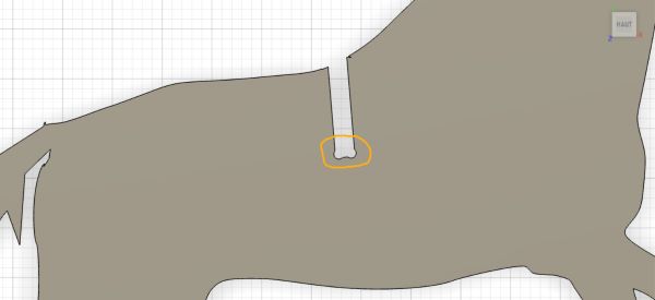
-
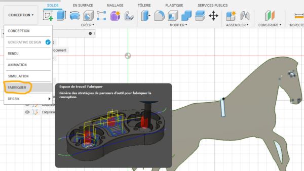
Go to Fabric
-
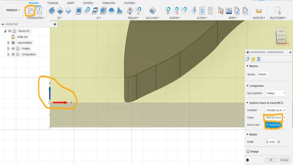
Click on “Confguration” and go to “WCS” to set the origin by selecting a point on the brut and by clicking on the left top point of your yellow square.
-
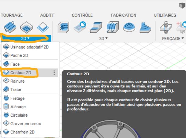
Click on “2D” and select the “2D contour”
-
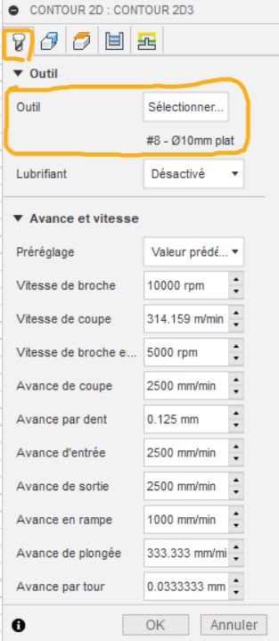
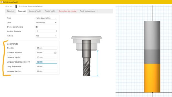
Now a new menu opened, click on “Select a Tool” and you will have to create the tool you are going to use. I selected the parameters with the help of my instructor.
-
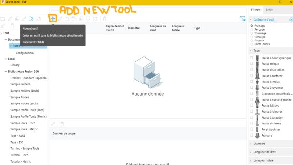
Add a new tool by clicking on the “+”
-
Select your tool parameters regarding your tool. Make some measures to be precise.
-
Put some tabs to make sure your object will not move during the cutting and will not project you material pieces.
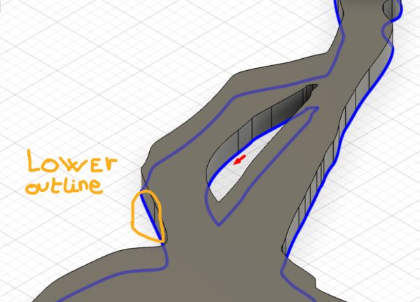
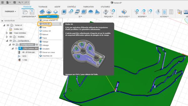
- Then add some “2D poche” for the close internal shape to cut
-
Click right on your final configuration and select “Post-treated”
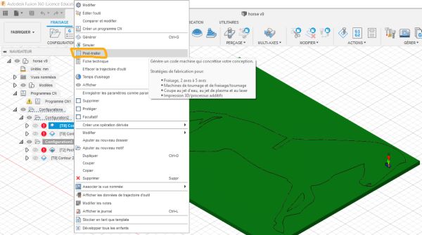
-
Select your machine and validate ! You have generate a file that you are goign to change into a “.nc” file and by the way you have to remove in the 14th line the “Z15.” caracters.
- Now you can put this file in the machine USB key !
That’s the render :
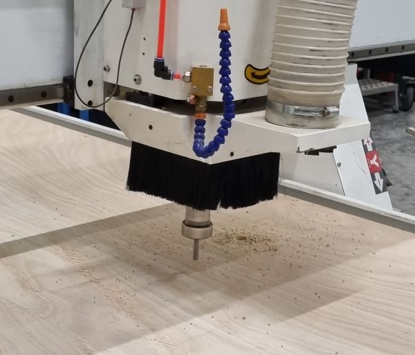
Cutting it !
First, choose the king of material you use. I use a 17.6mm startplak Okoume by Joubert Plywood. I launched the aspiration table and screwed the material on the sacrificial layer. The spindle is 24000
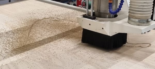
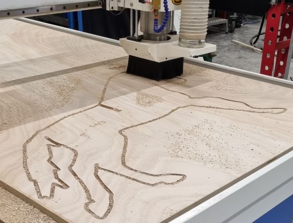
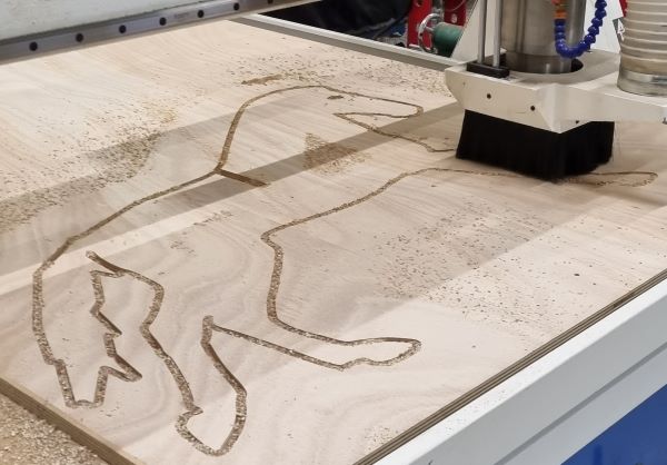
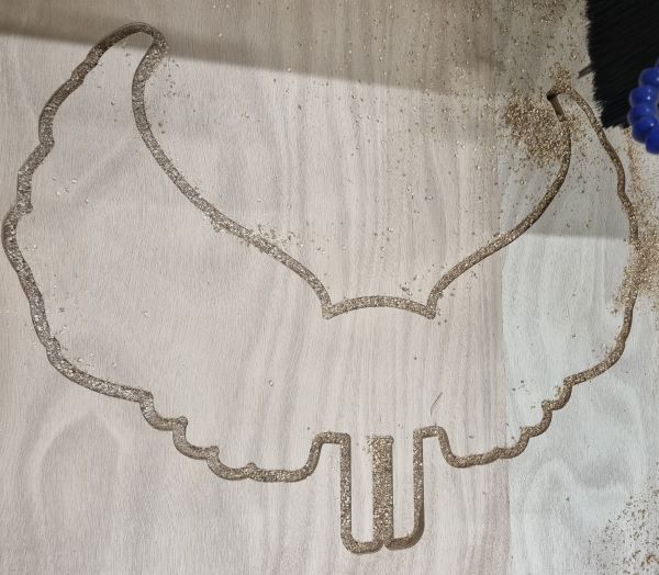
Here are the cuttings steps :
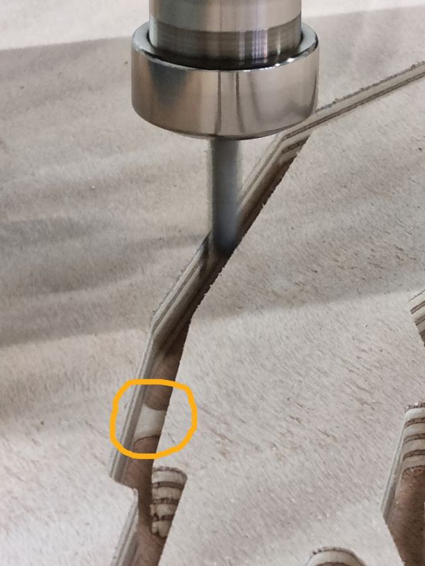
Keep you finger on stop just in case something goes wrong.
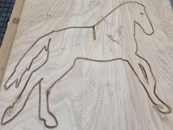
We had to make another cutting programm to remove the pieces left in the traces :
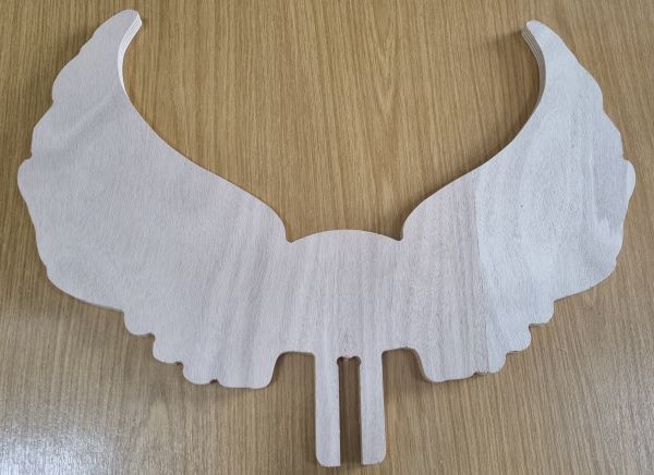
Here are the wings :
Group assignment with Theo Gautier from Agrilab
Safety Training
- Always look the machine when it’s working !
- Protect your ears with a cask or some ear plug protection.
- Protect your eyes with glass.
- Keep a security distance between you and the machine
- Keep you finger above the “STOP” button just in case…
Machine Limits
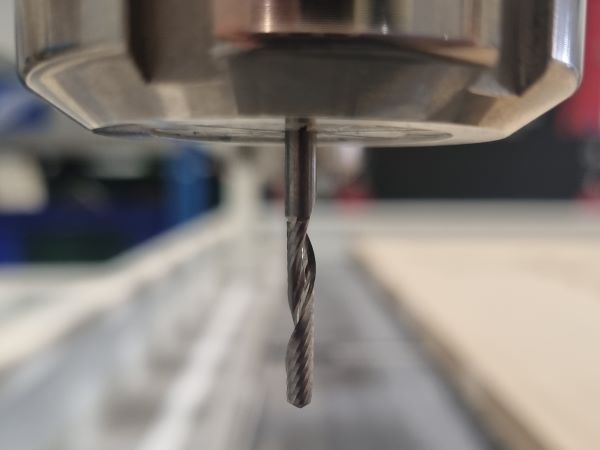
We used a 6 mm 2 flutes mill:
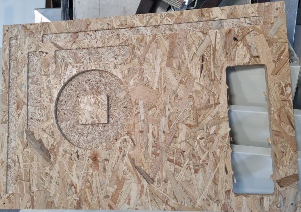
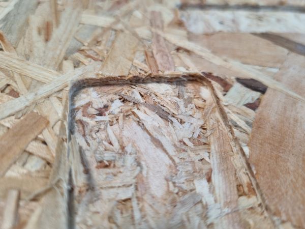
We tested the dogbones :
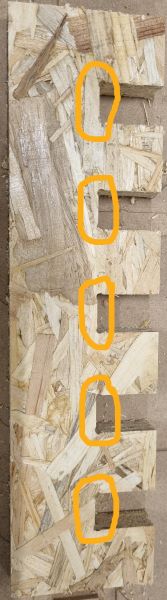
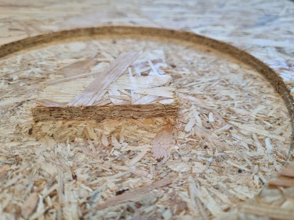
We also tested the alignment on the X and Y axis, the dimensions respect and the speed diferences :
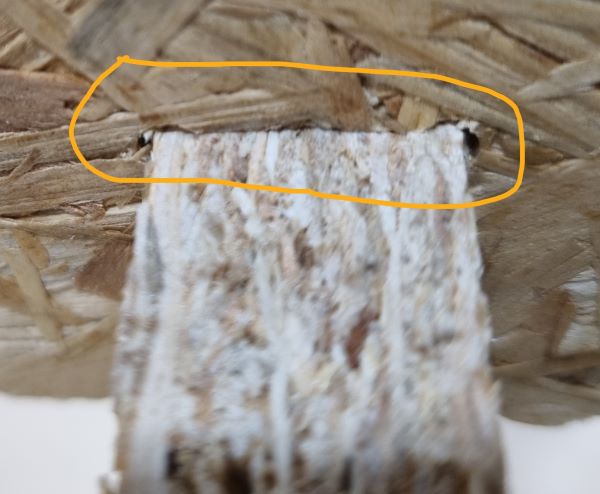
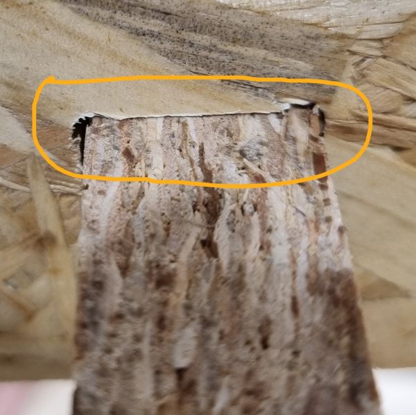
Internal and external Right Angle :
Conclusion :
- Be careful when machining
- On X and Y you loose about 1.5mm with the 6mm milling tool.
- If you increase the speed it degrades more the material. If you want a smooth result prefere a cool speed.
- You can make external right angle but not internal.