Output Devices
- Add an output device to a microcontroller board you’ve designed
- Program it to do something
- Measure the power consumption of an output device
This week I would like to deepen my understanding on the addressables RGB leds I want to use in my final project. I also would like to try other output devices as a speaker or a servo if I manage. For that I will certainly have to do another board because the SAMD11D I made run out of memory really fast with the Arduino libraries.
RGB Leds
During the Embedded Programming week I tested the FastLED library with my custom Arduino. It did not work due to an incompatibility between the SAMD11D I used and the library. I also tried the Neopixel library, which compiled but did’nt do anything to my leds. So this week I’m determined to understand the error and make it work !
Stephane advised me to look at the low-level protocol of the RGB leds I used: it seemed simple enough to be hard-coded. However I’m still new to low-level programming and it required some efforts to understand what the datasheet was talking about. Thankfully, my instructor set up a meeting with Quentin so I could be able to expose my issues and have the beginning of an answer. Quentin was of great help (thank you again), and I managed to understand more deeply the protocol. He also live-coded an example of a code which might work with the RGB leds.
Quentin’s code
#include <stdint.h>
#include "variant.h"

#define N_LED 3
#define N_COL 3

#define PIN_DATA 4
#define PORTA_OUT PORT->Group[PORTA].OUT

#define SET_HIGH(pin) PORTA_OUT.reg |= (1 << pin)
#define SET_LOW(pin) PORTA_OUT.reg &= ~(1 << pin)

byte grb_vec[N_LED][N_COL] = {{255, 0, 0}, {0, 0, 0}, {0, 0, 0}};

static inline void delayNanoseconds( unsigned int ) __attribute__((always_inline, unused)) ;
static inline void delayNanoseconds( unsigned int nsec ) {
    if ( nsec == 0 )
    {
        return ;
    }

    /*
    *  The following loop:
    *
    *    for (; ul; ul--) {
    *      __asm__ volatile("");
    *    }
    *
    *  produce the following assembly code:
    *
    *    loop:
    *      subs r3, #1        // 1 Core cycle
    *      bne.n loop         // 1 Core cycle + 1 if branch is taken
    */

    // VARIANT_MCK / 1000000 == cycles needed to delay 1uS
    //                     3 == cycles used in a loop
    // Divide by 3 before multiplication with usec, so that the maximum usable usec value
    // with the D51 @ 120MHz is at least what it was when multipling by usec first at 48MHz.
    uint32_t n = (nsec * ((VARIANT_MCK / 1000000) / 3)) / 1000;
    __asm__ __volatile__(
        "1:              \n"
        "   sub %0, #1   \n" // substract 1 from %0 (n)
        "   bne 1b       \n" // if result is not 0 jump to 1
        : "+r" (n)           // '%0' is n variable with RW constraints
        :                    // no input
        :                    // no clobber
    );
    // https://gcc.gnu.org/onlinedocs/gcc/Extended-Asm.html
    // https://gcc.gnu.org/onlinedocs/gcc/Extended-Asm.html#Volatile
}

void update_led() {
    byte col_ij;

    for (int i = 0; i < N_LED; i++) {
        for (int j = 0; j < N_COL; j++) {
            col_ij = grb_vec[i][j];
            for (int k = 7; k >= 0; k--) {
                if (col_ij & (1 << k)) {
                    // send 1
                    SET_HIGH(PIN_DATA);
                    delayNanoseconds(800);
                    SET_LOW(PIN_DATA);
                    delayNanoseconds(450);
                } else {
                    // send 0
                    SET_HIGH(PIN_DATA);
                    delayNanoseconds(400);
                    SET_LOW(PIN_DATA);
                    delayNanoseconds(850);
                }
            }
        }
    }

    SET_LOW(PIN_DATA);
    delayMicroseconds(55);
}

void setup() {
    pinMode(PIN_DATA, OUTPUT);
}

void loop() {
    update_led();
}
Nanoseconds away from success
On Thursday morning, armed with Quentin’s code and a logic analyzer I tried to make it work. The trick is the leds protocol needs nanoseconds precision to work: you need to send 1 and 0 at precise intervals, and it’s not reachable by a “simple” Arduino code.

That’s why Quentin used assembly language to reach this precision: we checked FastLED and Neopixel libraries to understand how they did that and copied some parts of the code to replicate it. The example below is taken from FastLED library, but we also tried with Neopixel library which use nop; to control the delays. We made seral experimentations to try to determine how many nanoseconds were a nop, but it was really hard to understand everything: we reached only 400ns, which was still too big for the precision we targeted in the first place.
static inline void delayNanoseconds( unsigned int ) __attribute__((always_inline, unused)) ;
static inline void delayNanoseconds( unsigned int nsec ) {
    if ( nsec == 0 )
    {
        return ;
    }

    uint32_t n = (nsec * ((VARIANT_MCK / 1000000) / 3)) / 1000;
    __asm__ __volatile__(
        "1:              \n"
        "   sub %0, #1   \n" // substract 1 from %0 (n)
        "   bne 1b       \n" // if result is not 0 jump to 1
        : "+r" (n)           // '%0' is n variable with RW constraints
        :                    // no input
        :                    // no clobber
    );
}
for (;;) {
    *set = pinMask;
    asm("nop; nop; nop; nop; nop; nop; nop; nop;");
    if (p & bitMask) {
    asm("nop; nop; nop; nop; nop; nop; nop; nop;"
        "nop; nop; nop; nop; nop; nop; nop; nop;"
        "nop; nop; nop; nop;");
    *clr = pinMask;
    } else {
    *clr = pinMask;
    asm("nop; nop; nop; nop; nop; nop; nop; nop;"
        "nop; nop; nop; nop; nop; nop; nop; nop;"
        "nop; nop; nop; nop;");
    }
    if (bitMask >>= 1) {
    asm("nop; nop; nop; nop; nop; nop; nop; nop; nop;");
    } else {
    if (ptr >= end)
        break;
    p = *ptr++;
    bitMask = 0x80;
    }
}
Assembler, or how to learn to be a jedi
As we reached no success in lightning LEDs, I wanted to go deeper into assembly language. But the Fab Academy is only the beginning, and I couldn’t abandon this week’s assignment and spend the week buried in assembly courses. So I made the choice to move on and try other things, but I gathered some interesting ressources about that, for later.
Assembler ressources
Adafruit NeoPixel library
As I was frustrated by my RGB leds, I tried again to understand why the Neopixel library compiled but didn’t work on my board. It’s then I realized the SAMD11D wasn’t defined in the main file. With little hope I added it…
#elif defined(__SAMD21E17A__) || defined(__SAMD21G18A__) || \
      defined(__SAMD21E18A__) || defined(__SAMD21J18A__) || \
      defined (__SAMD11C14A__) || defined(__SAMD11D14AS__)
I wasn’t expected it to be that simple but my example code actually worked! It was a relief after all this time.
#include <Arduino.h>
#include <Adafruit_NeoPixel.h>

#define PIN 23
#define NUMPIXELS 3

Adafruit_NeoPixel pixels(NUMPIXELS, PIN, NEO_GRB + NEO_KHZ800);

void setup() {
    pixels.begin();
    pixels.clear();
    pixels.show();
}

void loop() {
    pixels.clear();

    for(int i = 0; i < NUMPIXELS; i++) {
        pixels.setPixelColor(i, pixels.Color(119, 245, 135));
        pixels.show();
        delay(500);
    }
}
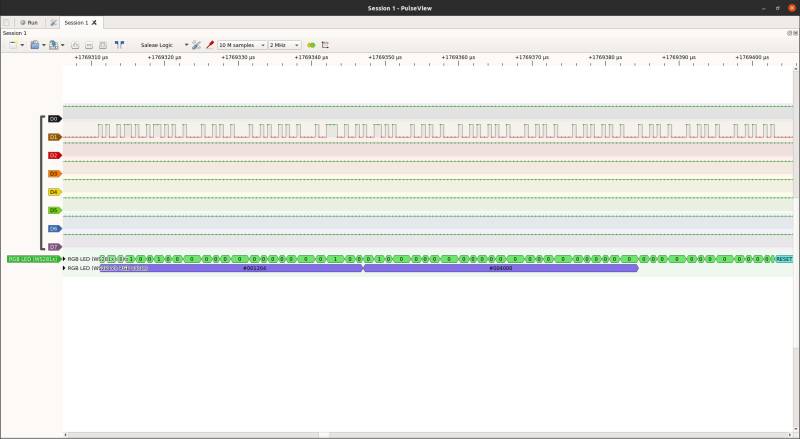
I then observed the signal with the Logic Analyzer to try to replicate that later if I can.
Understanding the Neopixel library
I read a lot about how to create a library for Arduino becasue I wanted to make the Neopixel library lighter. Unfortunately I ran out of time to do it properly, but I will keep these ressources for later.
Adafruit Neopixel library ressources
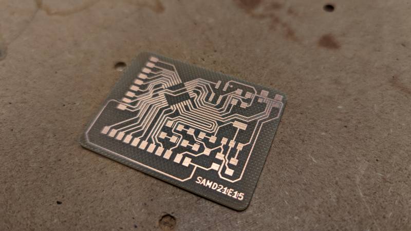
SAMD21E15
As I wanted to try more complex outputs, I chose to make a new board with a SAMD21. It has more flash memory than the SAMD11 and is widely supported as it’s used by Arudino itself. So I thought I was gonna be able to use a Servo motor or my mini Oled with this one. Unfortunately we don’t have the super powerful SAMD21E18 with 256kb of flash memory, but we have the 32kb SAMD21E15.
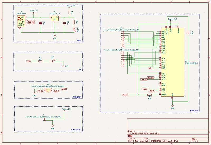
KiCAD
I designed the board on KiCAD following the SAMD21 datasheet and two documentations: Quentin Bolsee’s and Lingdong Huang’s.
I also found an helpful pinout for the SAMD21, this time I didn’t have to do it myself.

Schematics
I tried to respect the advices given during the Regional Review from the Electronics Design week and kept my habit of making a lot of labels to keep it clean. Although for the free pins I didn’t make the effort as it was easier to adapt from the PCB design than the other way around.
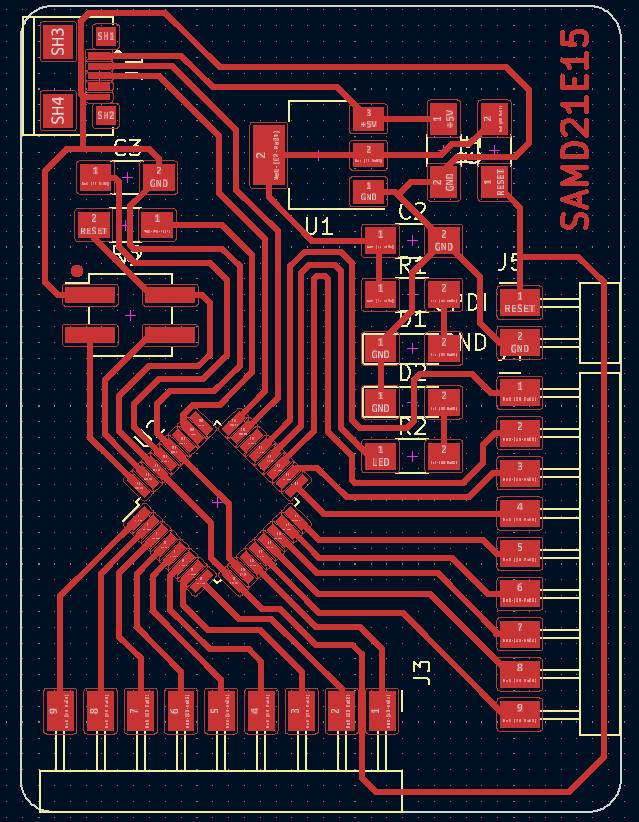
PCB Design
Bom file
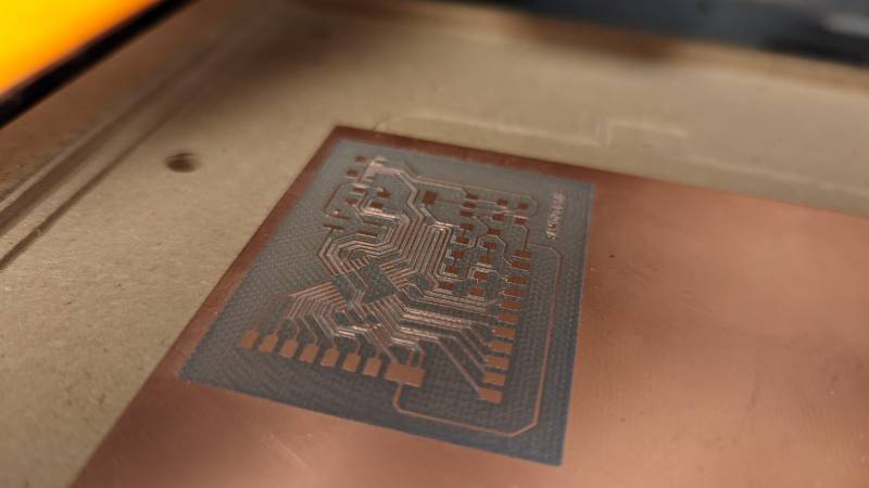
Milling
I milled the board with the SRM 20 as usual and used FlatCAM for preparing it. It was a smooth run, but I had to clean some traces afterwards with my multimeter friend. The milling job took a little more than an hour (25 minutes for the isolation, 35 minutes for cleaning copper, 4 minutes for the cutting job.)

Soldering
The soldering was challenging because I had a 20 pin MCU and a micro-USB connector and I haven’t try to solder something that small yet.
I started by soldering the MCU carefully using the extra-small soldering iron we use for SMD. It went well overall as I checked my work regularly with a multimeter. I then added the micro-USB connector following Stephane’s advices. I put a little solder on the pins and as I placed the micro-USB connector on them I used a hot air gun to fix it. I added a little solder on the biggest pins and it was done (spoiler: I had to add resolder later on because it wasn’t well fixed in the first place).


Careful with your RESET pin
Unfortunately I made a big mistake in my design: I followed badly the advice of Quentin’s documentation and added uncorrectly a resitor to the reset pin. Consequently I had to cut one of my tracks and abandon the idea of a resistor protecting the reset pin (it became a zero Ohm resistor to let the reset pin get its juice correctly).

After that I added the connectors and it was done. It’s beautiful, but does it work?
Programming (or at least trying to)
Flashing the SAMD21E15B
When trying to flash my board for the first time, I encountered several issues. First, there seemed to be no binaries adapted to my microchip. I found no SAMD21E15B but a SAMD21E15A and a SAML21E15B binaries. I tried both without success.
Debugger: Alex Taradov Generic CMSIS-DAP Adapter 548B520D v0.1 (S)
Clock frequency: 16.0 MHz
Error: unknown target device (DSU_DID = 0x10011527)
Following the advices I found here and here, I modified the source code of edbg to add the unrecognized address of my chip.
I added the ID detected to the corresponding source file target_cm0p.c.
It didn’t work either, I still had an unknown target device error. As I was running out of ideas (I read this but it didn’t help that much except for made me regret we didn’t have a SAMD21E18) and Stephane too, I asked Quentin about it. He advised me to read more carefully the source code from edbg to find where to cut the ID to be right. I found the mask used in the target_select function and used it to find the correct ID.
static void target_select(target_options_t *options)
{
uint32_t dsu_did, id, rev;
bool locked;

reset_with_extension();

dsu_did = dap_read_word(DSU_DID);
id = dsu_did & DEVICE_ID_MASK;
rev = (dsu_did >> DEVICE_REV_SHIFT) & DEVICE_REV_MASK;

for (int i = 0; i < ARRAY_SIZE(devices); i++)
{
    if (devices[i].dsu_did != id)
    continue;

    verbose("Target: %s (Rev %c)\n", devices[i].name, 'A' + rev);

    target_device = devices[i];
    target_options = *options;

    target_check_options(&target_options, devices[i].flash_size, FLASH_ROW_SIZE);

    locked = dap_read_byte(DSU_STATUSB) & DSU_STATUSB_PROT;

    if (locked && !options->unlock)
    error_exit("target is locked, unlock is necessary");

    if (!locked)
    finish_reset();

    return;
}

error_exit("unknown target device (DSU_DID = 0x%08x)", dsu_did);
}
The result of 0xfffff0ff & 0x10011527 is 0x10011027.
I was then able to use edbg as a bootloader, and chose to use the SAMD21E15A as Quentin told me they weren’t that different.
Pull request to edbg
Quentin advised me to make a pull request to edbg. I never did something like that before, so I looked how to do it, it’s really exciting!
How to make a pull request
- Fork the project
- Clone it to your local system
- Make a new branch
- Make your changes
- Push it back to your repo
- Click the Compare & pull request button
- Click Create pull request to open a new pull request
- Wait for it to be approved
My pull request is actually waiting for approval, I will update this page if it gets approved (or dismissed). Edit: it was approved!
Uploading a code to the SAMD21E15B
However, as I thought I was getting out of my misery I was not able to upload a simple blink sketch to my board, and the error didn’t make any sense to me.
With Stephane we tried several ways, even using an Atmel ICE as a programmer to test it, but with no chance.
Arduino uplaod error
/home/ejoz/.arduino15/packages/arduino/tools/arm-none-eabi-gcc/4.8.3-2014q1/bin/arm-none-eabi-size -B /tmp/arduino_build_891505/Blink.ino.elf
text       data        bss        dec        hex    filename
10288          0       1964      12252       2fdc    /tmp/arduino_build_891505/Blink.ino.elf
/home/ejoz/.arduino15/packages/arduino/tools/arm-none-eabi-gcc/4.8.3-2014q1/bin/arm-none-eabi-size -A /tmp/arduino_build_891505/Blink.ino.elf
Sketch uses 9936 bytes (40%) of program storage space. Maximum is 24576 bytes.
Forcing reset using 1200bps open/close on port /dev/ttyACM0
PORTS {/dev/ttyACM0, } / {/dev/ttyACM0, } => {}
PORTS {/dev/ttyACM0, } / {/dev/ttyACM0, } => {}
PORTS {/dev/ttyACM0, } / {/dev/ttyACM0, } => {}
PORTS {/dev/ttyACM0, } / {/dev/ttyACM0, } => {}
PORTS {/dev/ttyACM0, } / {/dev/ttyACM0, } => {}
PORTS {/dev/ttyACM0, } / {/dev/ttyACM0, } => {}
PORTS {/dev/ttyACM0, } / {/dev/ttyACM0, } => {}
PORTS {/dev/ttyACM0, } / {/dev/ttyACM0, } => {}
PORTS {/dev/ttyACM0, } / {/dev/ttyACM0, } => {}
PORTS {/dev/ttyACM0, } / {/dev/ttyACM0, } => {}
PORTS {/dev/ttyACM0, } / {/dev/ttyACM0, } => {}
PORTS {/dev/ttyACM0, } / {/dev/ttyACM0, } => {}
PORTS {/dev/ttyACM0, } / {/dev/ttyACM0, } => {}
PORTS {/dev/ttyACM0, } / {/dev/ttyACM0, } => {}
PORTS {/dev/ttyACM0, } / {/dev/ttyACM0, } => {}
PORTS {/dev/ttyACM0, } / {/dev/ttyACM0, } => {}
PORTS {/dev/ttyACM0, } / {/dev/ttyACM0, } => {}
PORTS {/dev/ttyACM0, } / {/dev/ttyACM0, } => {}
PORTS {/dev/ttyACM0, } / {/dev/ttyACM0, } => {}
PORTS {/dev/ttyACM0, } / {/dev/ttyACM0, } => {}
Uploading using selected port: /dev/ttyACM0
/home/ejoz/.arduino15/packages/Fab_SAM_Arduino/tools/bossac/1.7.0-mattairtech-3/bossac -i -d --port=ttyACM0 -U true -i -e -w -v /tmp/arduino_build_891505/Blink.ino.bin -R
SAM-BA operation failed
readWord(addr=0)=0x20000ffc
readWord(addr=0xe000ed00)=0x410cc601
readWord(addr=0x41002018)=0x10011527
An error occurred while uploading the sketch
version()=v2.0 [Arduino:XYZ] Aug 31 2021 13:59:21
chipId=0x10010027
Connected at 921600 baud
readWord(addr=0)=0x20000ffc
readWord(addr=0xe000ed00)=0x410cc601
readWord(addr=0x41002018)=0x10011527
Atmel SMART device 0x10010027 found
write(addr=0x20000800,size=0x34)
writeWord(addr=0x20000830,value=0x10)
writeWord(addr=0x20000820,value=0x20001000)
Device       : ATSAMD21E15B
readWord(addr=0)=0x20000ffc
readWord(addr=0xe000ed00)=0x410cc601
readWord(addr=0x41002018)=0x10011527
Chip ID      : 10010027
version()=v2.0 [Arduino:XYZ] Aug 31 2021 13:59:21
Version      : v2.0 [Arduino:XYZ] Aug 31 2021 13:59:21
Address      : 8192
Pages        : 384
Page Size    : 64 bytes
Total Size   : 24KB
Planes       : 1
Lock Regions : 16
Locked       : readWord(addr=0x41004020)=0xffff
readWord(addr=0x41004020)=0xffff
readWord(addr=0x41004020)=0xffff
readWord(addr=0x41004020)=0xffff
readWord(addr=0x41004020)=0xffff
readWord(addr=0x41004020)=0xffff
readWord(addr=0x41004020)=0xffff
readWord(addr=0x41004020)=0xffff
readWord(addr=0x41004020)=0xffff
readWord(addr=0x41004020)=0xffff
readWord(addr=0x41004020)=0xffff
readWord(addr=0x41004020)=0xffff
readWord(addr=0x41004020)=0xffff
readWord(addr=0x41004020)=0xffff
readWord(addr=0x41004020)=0xffff
readWord(addr=0x41004020)=0xffff
none
readWord(addr=0x41004018)=0
Security     : false
Boot Flash   : true
readWord(addr=0x40000834)=0x7000a
BOD          : true
readWord(addr=0x40000834)=0x7000a
BOR          : true
Arduino      : FAST_CHIP_ERASE
Arduino      : FAST_MULTI_PAGE_WRITE
Arduino      : CAN_CHECKSUM_MEMORY_BUFFER
Erase flash
chipErase(addr=0x2000)
done in 0.091 seconds

Write 10288 bytes to flash (161 pages)
write(addr=0x20000c00,size=0x1000)
writeBuffer(scr_addr=0x20000c00, dst_addr=0x2000, size=0x1000)
I also tried to upload the code directly in command line, with and without the port definition, without success either.
The device is not found on the port.
The device is found, but no success on the operation.
ejoz@ejoz-xps-13:~/.arduino15/packages/Fab_SAM_Arduino/tools/bossac/1.7.0-mattairtech-3$ ./bossac -i -d -U true -i -e -w -v /tmp/arduino_build_552986/Blink.ino.bin -R
Trying to connect on ttyACM0
Set binary mode
readWord(addr=0)=0x20000ffc
readWord(addr=0xe000ed00)=0x410cc601
readWord(addr=0x41002018)=0x10011527
version()=v2.0 [Arduino:XYZ] Aug 31 2021 13:59:21
chipId=0x10010027
Connected at 921600 baud
Device found on ttyACM0
readWord(addr=0)=0x20000ffc
readWord(addr=0xe000ed00)=0x410cc601
readWord(addr=0x41002018)=0x10011527
Atmel SMART device 0x10010027 found
write(addr=0x20000800,size=0x34)
writeWord(addr=0x20000830,value=0x10)
writeWord(addr=0x20000820,value=0x20001000)
Device       : ATSAMD21E15B
readWord(addr=0)=0x20000ffc
readWord(addr=0xe000ed00)=0x410cc601
readWord(addr=0x41002018)=0x10011527
Chip ID      : 10010027
version()=v2.0 [Arduino:XYZ] Aug 31 2021 13:59:21
Version      : v2.0 [Arduino:XYZ] Aug 31 2021 13:59:21
Address      : 8192
Pages        : 384
Page Size    : 64 bytes
Total Size   : 24KB
Planes       : 1
Lock Regions : 16
Locked       : readWord(addr=0x41004020)=0xffff
readWord(addr=0x41004020)=0xffff
readWord(addr=0x41004020)=0xffff
readWord(addr=0x41004020)=0xffff
readWord(addr=0x41004020)=0xffff
readWord(addr=0x41004020)=0xffff
readWord(addr=0x41004020)=0xffff
readWord(addr=0x41004020)=0xffff
readWord(addr=0x41004020)=0xffff
readWord(addr=0x41004020)=0xffff
readWord(addr=0x41004020)=0xffff
readWord(addr=0x41004020)=0xffff
readWord(addr=0x41004020)=0xffff
readWord(addr=0x41004020)=0xffff
readWord(addr=0x41004020)=0xffff
readWord(addr=0x41004020)=0xffff
none
readWord(addr=0x41004018)=0
Security     : false
Boot Flash   : true
readWord(addr=0x40000834)=0x7000a
BOD          : true
readWord(addr=0x40000834)=0x7000a
BOR          : true
Arduino      : FAST_CHIP_ERASE
Arduino      : FAST_MULTI_PAGE_WRITE
Arduino      : CAN_CHECKSUM_MEMORY_BUFFER
Erase flash
chipErase(addr=0x2000)
done in 0.090 seconds

Write 10280 bytes to flash (161 pages)
write(addr=0x20000c00,size=0x1000)
writeBuffer(scr_addr=0x20000c00, dst_addr=0x2000, size=0x1000)

SAM-BA operation failed
I then tried to upload the code directly with my SWD programmer, and obtained another error.
Error uploading with the SWD
/home/ejoz/.arduino15/packages/arduino/tools/arm-none-eabi-gcc/4.8.3-2014q1/bin/arm-none-eabi-size -B /tmp/arduino_build_552986/Blink.ino.elf
text       data        bss        dec        hex    filename
10168          0       1772      11940       2ea4    /tmp/arduino_build_552986/Blink.ino.elf
/home/ejoz/.arduino15/packages/arduino/tools/arm-none-eabi-gcc/4.8.3-2014q1/bin/arm-none-eabi-size -A /tmp/arduino_build_552986/Blink.ino.elf
Sketch uses 9816 bytes (79%) of program storage space. Maximum is 12288 bytes.
/home/ejoz/.arduino15/packages/arduino/tools/openocd/0.9.0-arduino/bin/openocd -d2 -s /home/ejoz/.arduino15/packages/arduino/tools/openocd/0.9.0-arduino/share/openocd/scripts/ -f /home/ejoz/.arduino15/packages/Fab_SAM_Arduino/hardware/samd/1.6.18-alpha2/variants/Generic_D11D14AS/openocd_scripts/SAMD11D14AS.cfg -c telnet_port disabled; program {{/tmp/arduino_build_552986/Blink.ino.elf}} verify reset; shutdown
Open On-Chip Debugger 0.9.0-gd4b7679 (2014-10-03-00:26)
Licensed under GNU GPL v2
For bug reports, read
    http://openocd.org/doc/doxygen/bugs.html
debug_level: 2
Info : only one transport option; autoselect 'swd'
adapter speed: 500 kHz
adapter_nsrst_delay: 100
cortex_m reset_config sysresetreq
Info : CMSIS-DAP: SWD  Supported
Info : CMSIS-DAP: Interface Initialised (SWD)
Info : CMSIS-DAP: FW Version = v0.1
Info : SWCLK/TCK = 1 SWDIO/TMS = 1 TDI = 0 TDO = 0 nTRST = 0 nRESET = 1
Info : CMSIS-DAP: Interface ready
Info : clock speed 500 kHz
Info : SWD IDCODE 0x0bc11477
Info : at91samd11d14as.cpu: hardware has 4 breakpoints, 2 watchpoints
target state: halted
target halted due to debug-request, current mode: Thread
xPSR: 0x01000000 pc: 0x000004a0 msp: 0x20000ffc
** Programming Started **
auto erase enabled
Error: Couldn't find part corresponding to DID 10011527
Error: auto_probe failed
Runtime Error: embedded:startup.tcl:454: ** Programming Failed **
in procedure 'program'
in procedure 'program_error' called at file "embedded:startup.tcl", line 510
at file "embedded:startup.tcl", line 454
the selected serial port at file "embedded:startup.tcl", line 454
does not exist or your board is not connected
I also tried directly from the Arduino extension in VSCode, just for fun at this stage, I wasn’t expected it to work.
After that I was fairly discouraged, but then Eduardo shared a medium article about learning and performing, and I was slightly cheered up. I may have not performed, but I learned so much!
Nick Soderstrom, Ph.D., Learning vs. Performance: A Distinction Every Educator Should Know
The learning strategies that fall under this category are called desirable difficulties (Bjork, 1994). They are desirable because they lead to better long-term retention and transfer of knowledge, and they are difficult because they pose challenges that slow the rate of current progress and induce more mistakes during instruction or training.
Power consumption


We measured the power consumption of a DC motor by plugging it to a power supply and we also used a multimeter in serie.
To calcutate the consumption, we need to use the formula \(P = V * I\).
In this case, \(P = 12V * 0.64mA = 7.68W\)
About this week
As I did succeed to program my addressables leds, I was frustrated to not be able to go further with the assembly lamguage, and to fail to program my SAMD21E15B. I’m considering switching to ATtiny chips for my final project to make things simpler for myself. I may add a SAM11C to enable USB connection (and as I thought of doing that, Quentin already did it!)
During Input Devices week, I made another version of my board with a SAMD21E17 kindly send to us by AgriLab. It was such a joy to make it blink without problems!