Computer Controlled Machining
- Do your lab’s safety training
- Test runout, alignment, fixturing, speeds, feeds, materials, and toolpaths for your machine
- Make (design, mill and assemble) something big (~meter-scale)
This week is the most frightening to me, as I never made something big in my life (except for ikea furnitures, but I doubt this will help me). I decided to make something simple to make sure I finish it in time. And we also will meet AgriLab on Moday, and as exciting as it is, it’s one day I will not be able to work in the lab: I need to be efficient!
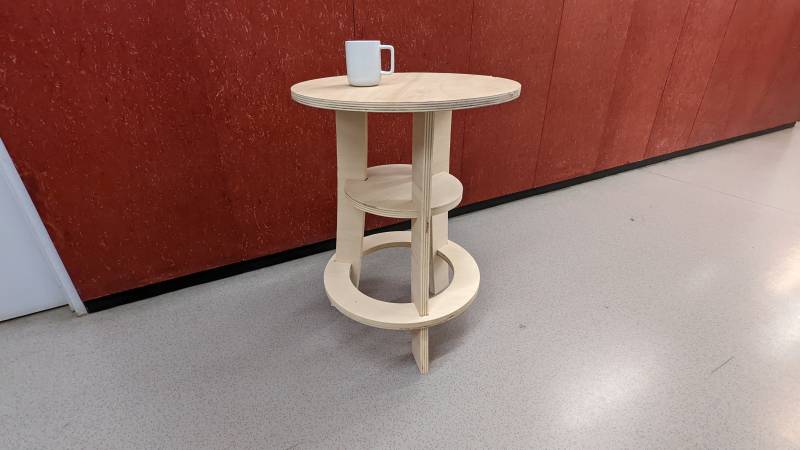
Hero shot of the big something
CNC training
Danger
During the lecture, Neil frightened me by telling an horrible story of a student who died using a CNC. As I was already afraid, it was a bit too much 
But during the Student bootcamp Stephane showed me how to use the ShopBot and as long as I follow the rules there is no reason anything could go wrong. I just need to be extra careful with my natural clumsiness this week and I’ll be safe!
Preparation
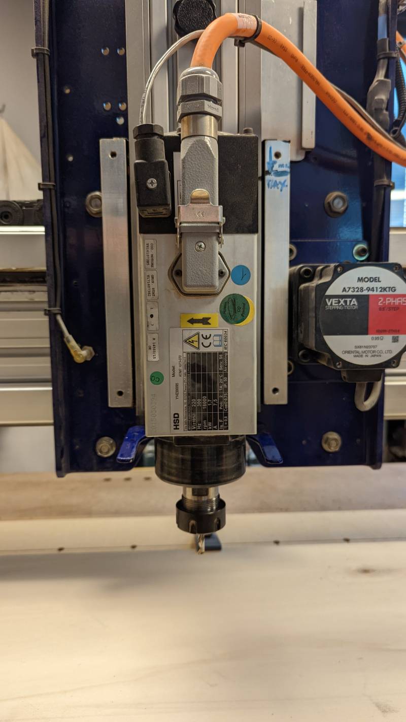
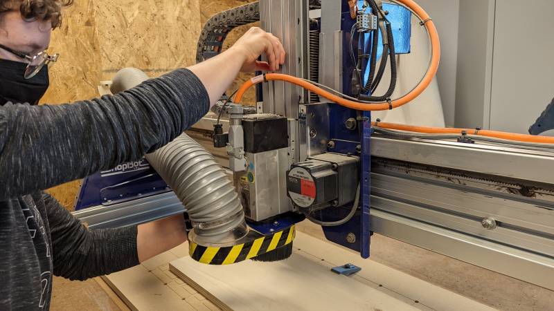
At the lab we have a dedicated room for the CNC machine. the CNC is a ShopBot PRSalpha 120-60: it is not that large, but it’s enough to everyday tasks in the lab. For the assignement I just need to be careful to not design too large parts or to nest them diagonally.
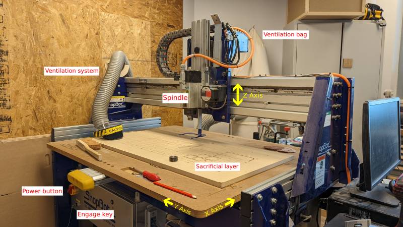
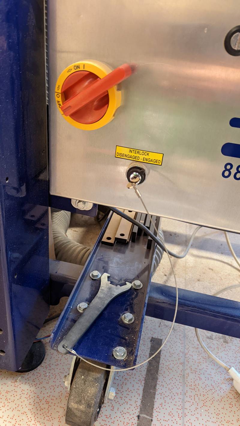
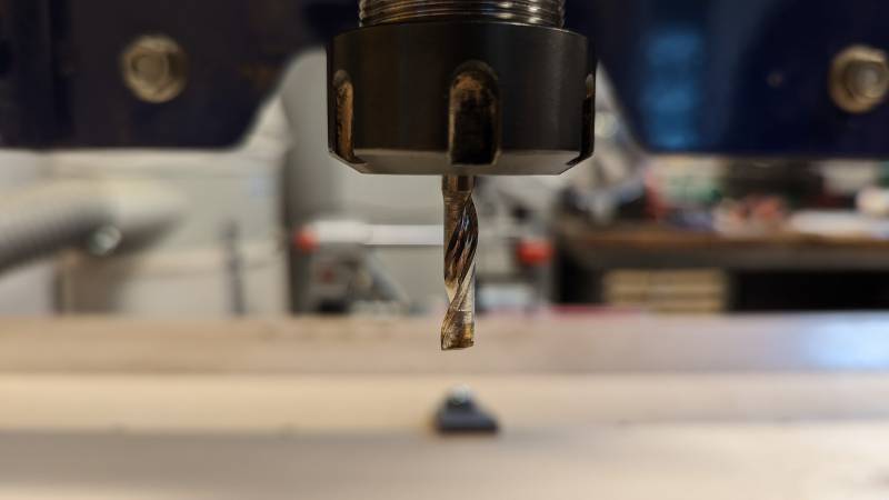
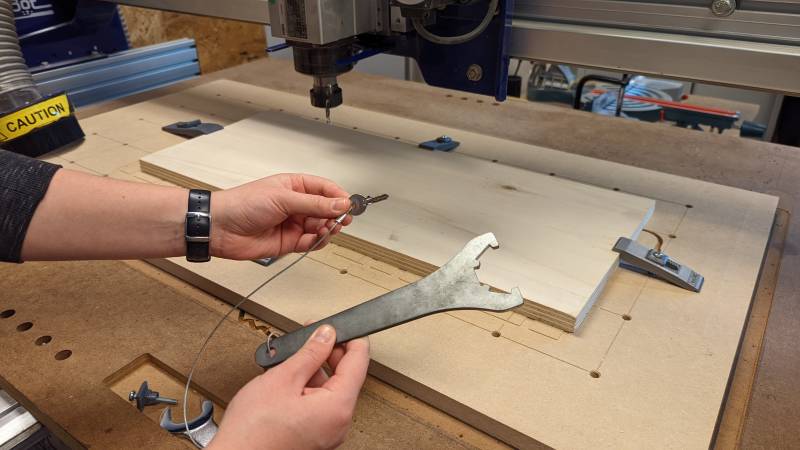
The main parts of the CNC are indicated on the picture above, and you can see below a closup on two important parts of the machine: the power button and the engage key on the left, and the spindle and Z axis on the right. You can see that the engage key is linked to the key that allows us to remove an endmill from the spindle: that way we can’t touch the spindle without disengaging it: one point for safety!
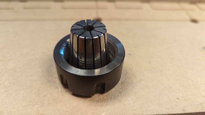
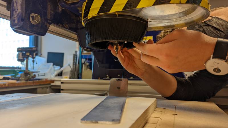
To prepare the milling job, we need to insert the endmill on the spindle. We use a collet adapted to the size of the endmill and insert it into the spindle without tightening it at first.
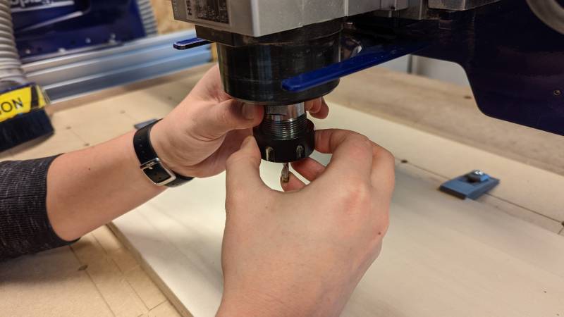
After that we can insert the mill and tighten up by hand: you can see on the picture on the left that I need to hold the endmill with one finger to tight everything in place. The endmill needs to be inserted untill only its milling part is protruding.
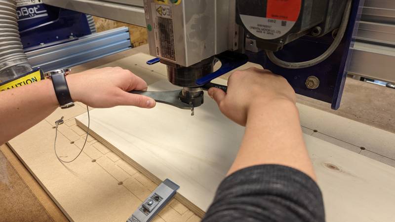
We can then tight the endmill with the key showed before: only do this step with a disengaged spindle.
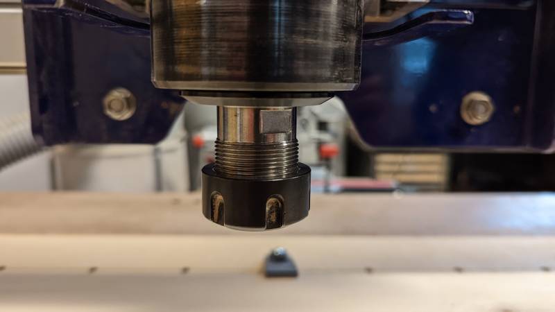
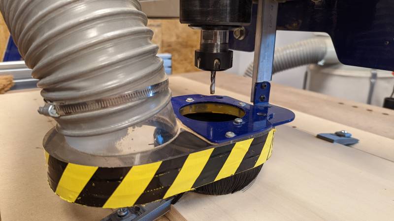
We can now plug in the ventilation system below the endmill, lift it up around the mill and tight the Z axis.
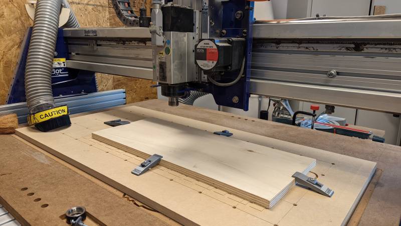
And now it’s time to put the plank on the sacrificial board! We use either 3D printing part to keep it in place or double-sided tape. For the big something we also used wood screws.
The machine is ready, we can now switch to the computer controlled part!
Operation
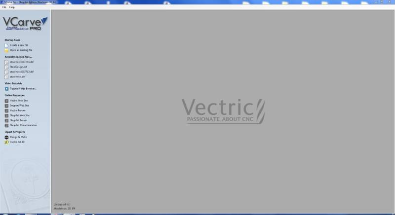
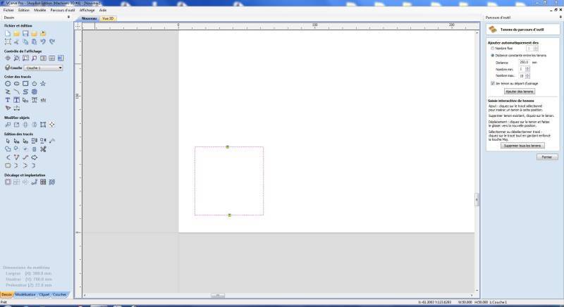
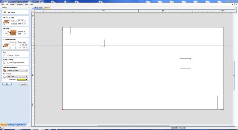
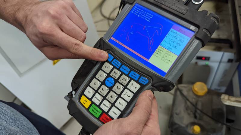
To operate the machine, we use VCarve Pro. It’s pretty intuitive with a lot of very understandable icons. You first need to indicate some informations about your material: its size, thickness, where you want to indicate the X and Y axis. After that you can even draw or import your job. In this case we were testing so we draw a simple 5*5 square.
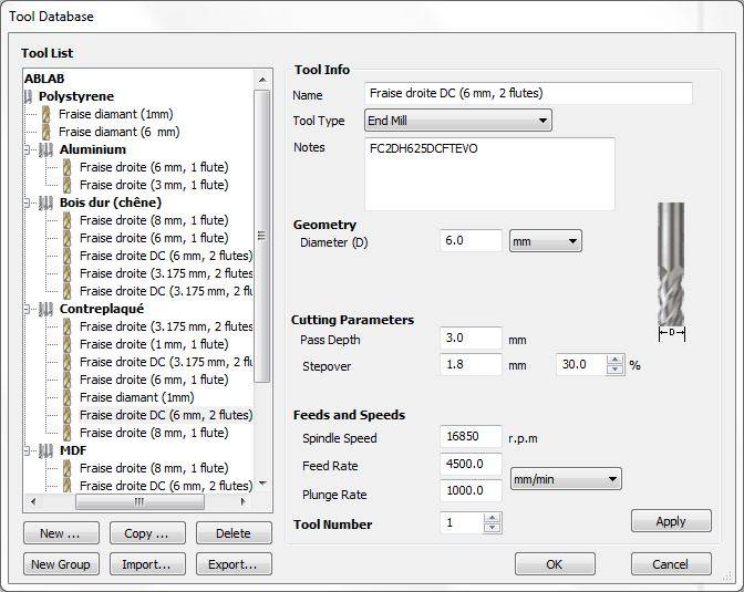
We then have to decide which endmill to use and indicates its parameters.
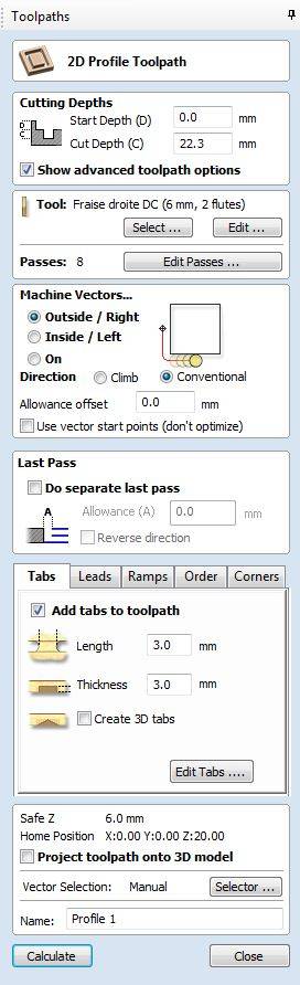
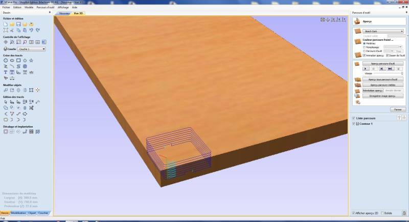
After that we can decide which operation to make, add tabs and ramps and finally preview our job on the screen. I will detail these operations longer in the final design as it will be more interesting than on a simple square.
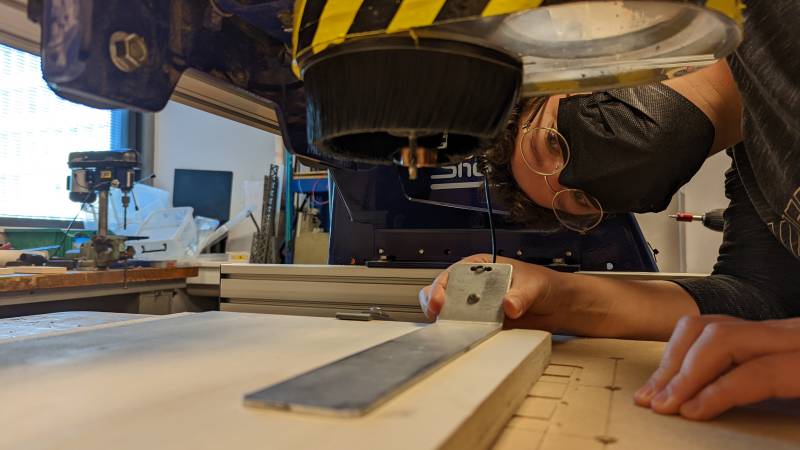
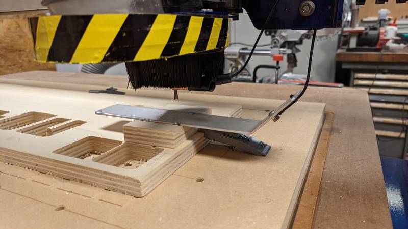
Finally we need to zero the board thanks to the ShopBot software. We need to put a metal clamp on the mill and a metal plank on the board (and be careful on the zero that we defined earlier). Once done, we can click on the zero button and let the machine go up and down twice (wear protective glasses and keep the emergency stop button at hand).
We can now launch the job after verifying nothing is left on the surface of the plank.
Warning
When the job is launched, be aware of every little details: sound, movements, smells… If something looks funny, stop the job. If you hear a weird noise, stop the job. You will always be able to restart the job if nothing was happening.
Post processing
Once the job is done, breathe.
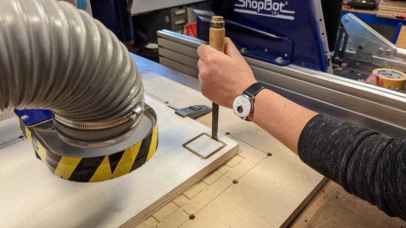
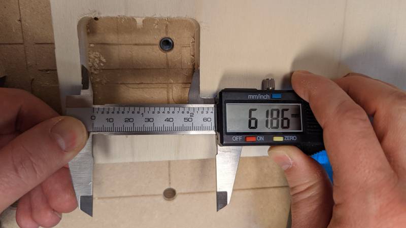
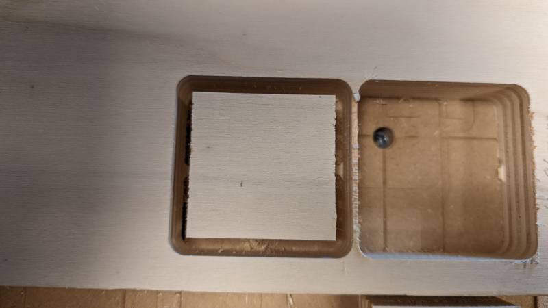
You can then move on the X and Y axis to remove the spindle from the job and have a better view. You can see on the pictures below the tabs we added on VCarve to maintain the square in place. I removed them with a cheasel to free the part before measuring.

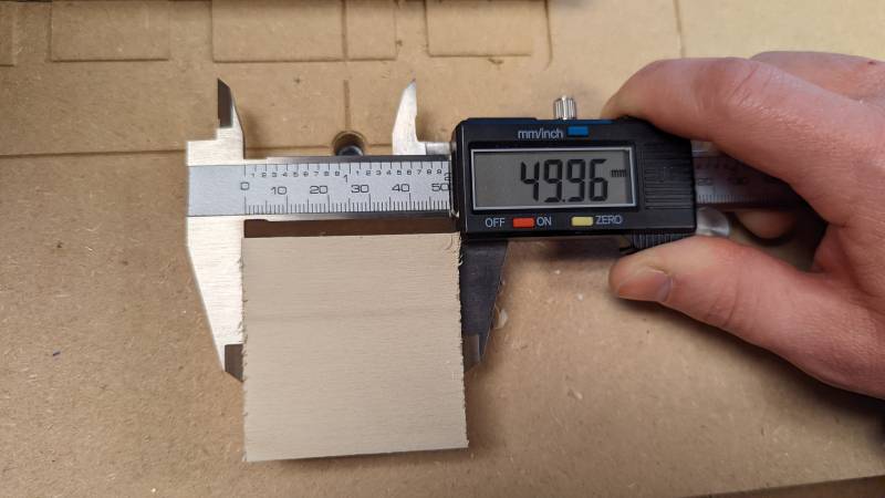
I measured the exterior of the square and the interior of the cutted part: the mill is 6mm wide, so it fits with the estimation.
We did two tests with two different endmills: one upcut and the other downcut (butterfly). The upcut endmill will have a better result on the bottom of the piece when the downcut will do the opposite. Having two flutes, the downcut one was better in finishing.
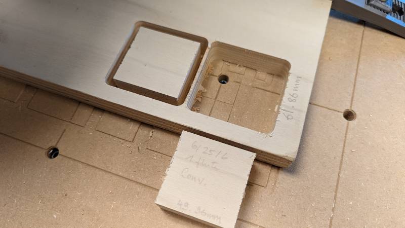
Missing
picture of the difference between the two squares.
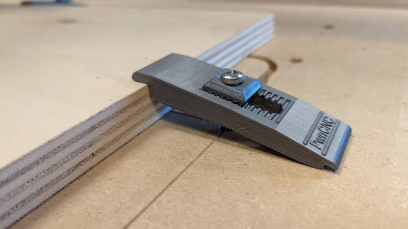
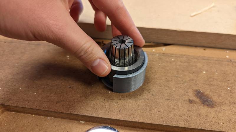
Once you get your parts, you can remove the collet easily with a handy 3D printed tool.
Feeds & Speeds
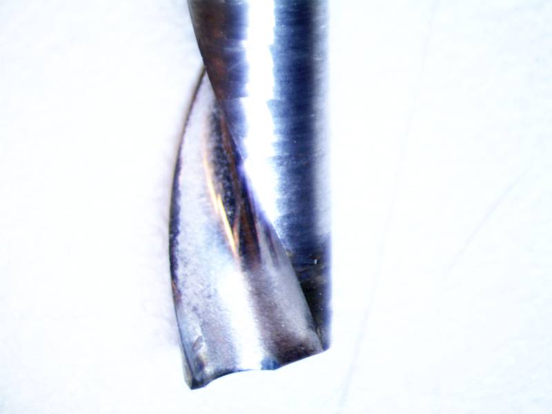
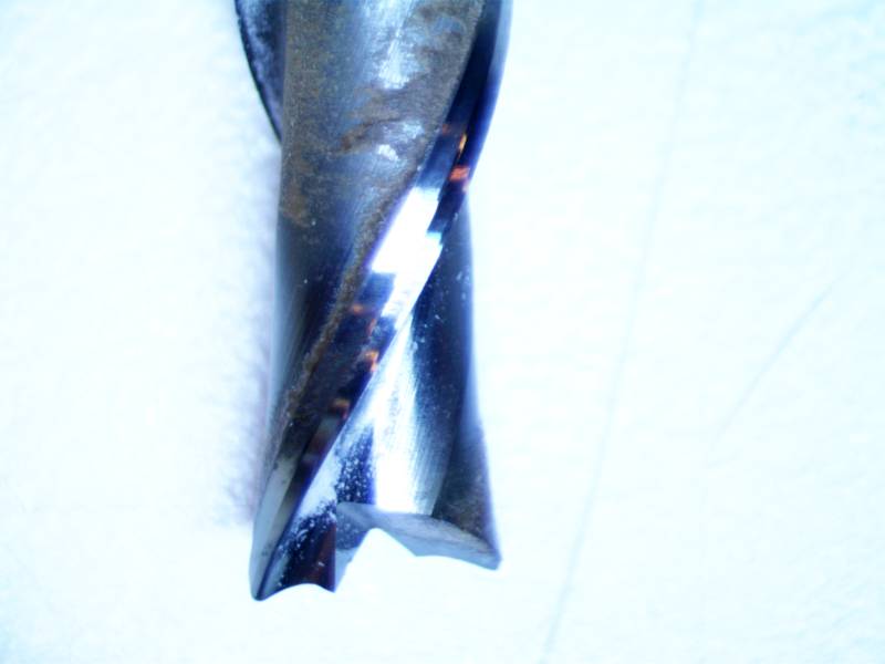
I used mainly two endmills during this week. One upcut and the other downcut (or butterfly). The upcut one does a better job on the bottom of the piece and cuts better through the all material, and the downcut allows a better finish on the top and sides, but performs poorly on the bottom. You will read later that I chose to use both to cut the final design this week.
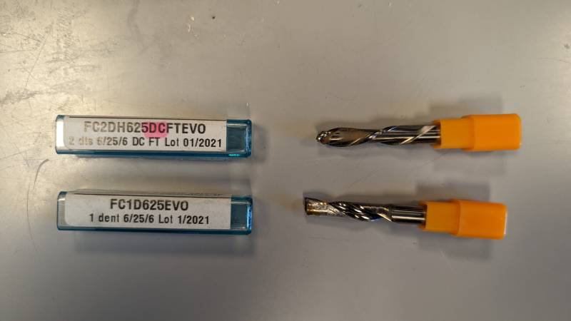
With the microscope I took pictures of the two endmills: the upcut one on the left, the butterfly one on the right.
Make something big
3D design
I usually do miniatures, it is a new area to me to make big things 
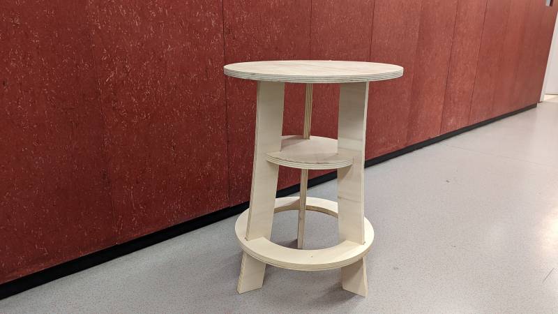
I decided to make a parametric stool or table. It’s a challenging experience as I have no idea how to start! I looked at designs on Pinterest to have some inspiration and decided to make a simple one. My first test is with a circle, but I may be changing that to a triangle (or make one each?).
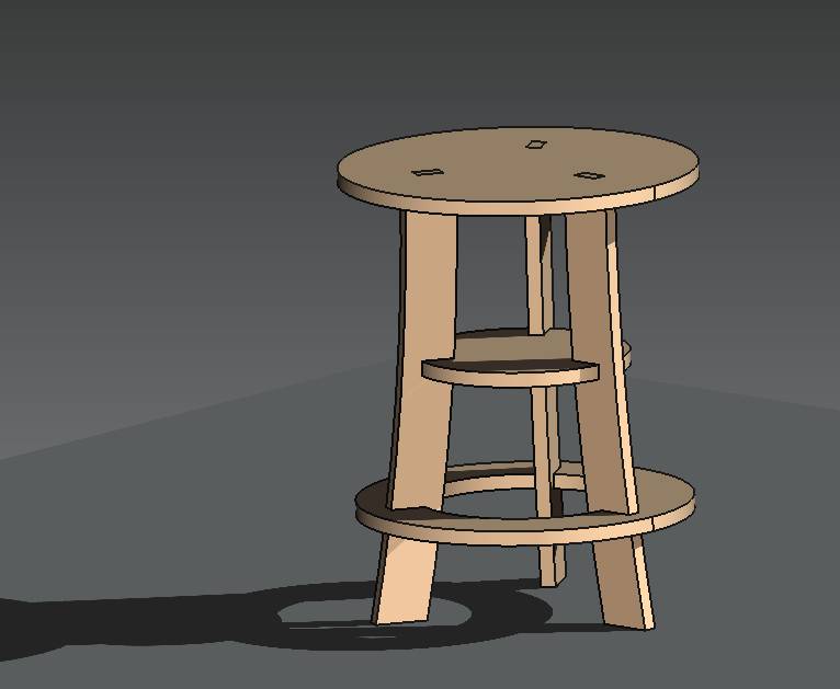
I used FreeCAD to make an entirely parametric model. To have a better idea on how I proceeded, you can look into the Computer Aided Design week or the Computer Controlled Cutting week
Iterations
To make sure I was heading in the right direction, I decided to make several tests. One on the CNC to test my joints designs with the final material, and one with the laser cutter to test the assembly process.
Joints tests
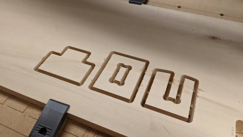
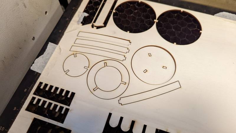
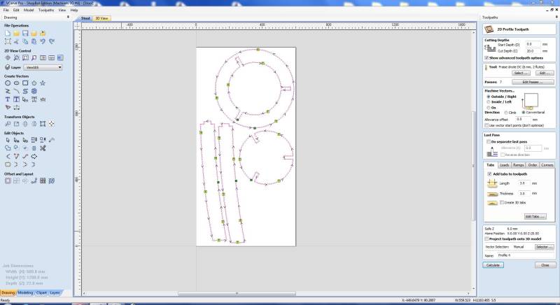
I first started by importing my design in VCarve to test the joints.
Export formats
As I opened my .dxf file in VCarve, I encountered a problem due to my export paramameters: I need to use DXF 14 otherwise my file won’t open correctly.
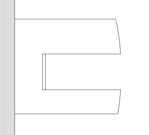
I still needed to remove some lines to correct the design on VCarve.
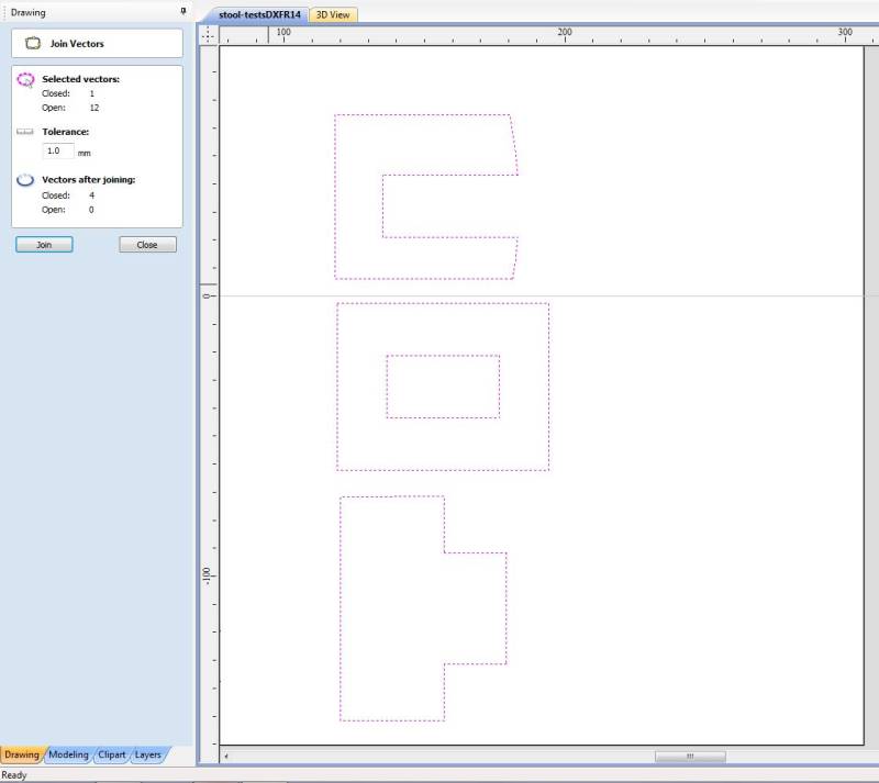
I think this is linked to the way I export my designs from FreeCAD, I really need to figure this out when I’ll have some more spare time. I also used the convenient function Join opened vectors from VCarve to close all my lines before milling.
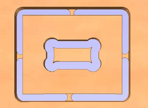
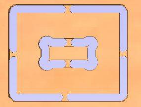
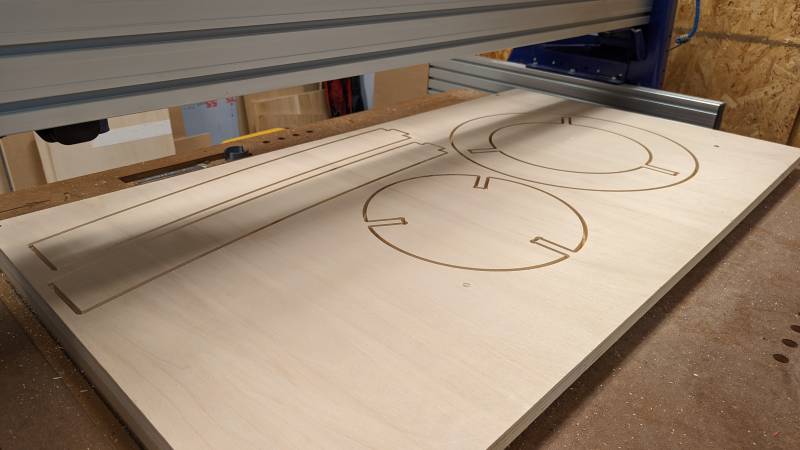
I then added dogbones and tabs to secure my parts on the plank.
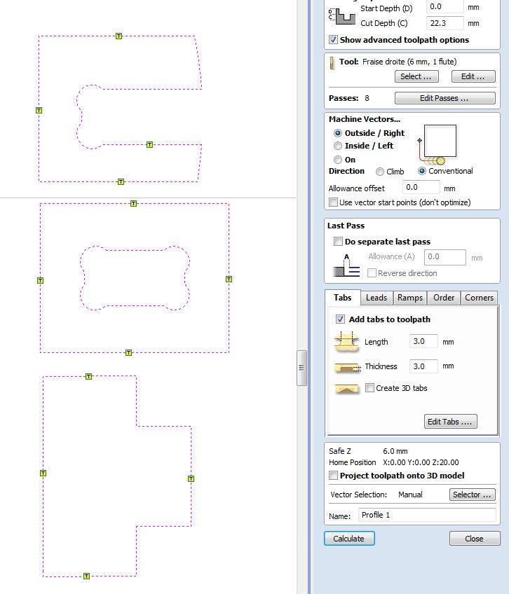
You can see below that I didn’t add them inside at first: thanks to the preview tool I noticed that the middle part would be totally loose during the milling, so I corrected my mistake.
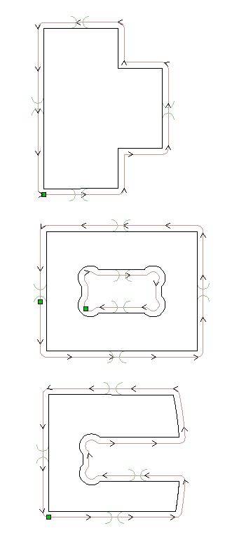
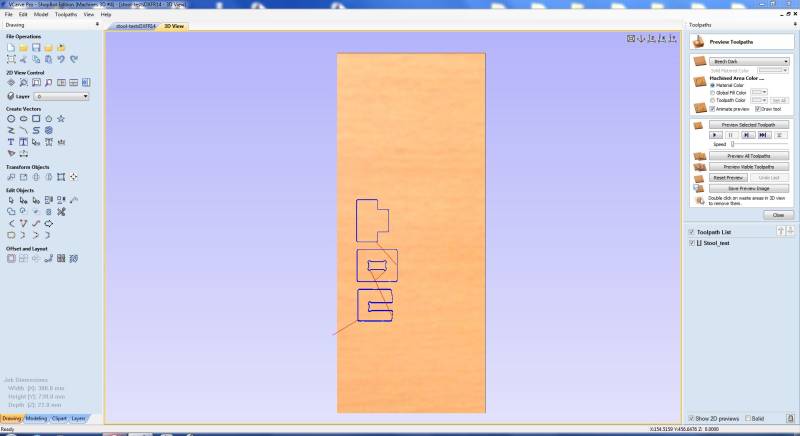
I finally calculated the job and obtained the tool path and the preview.
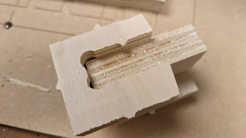
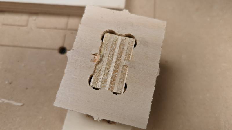
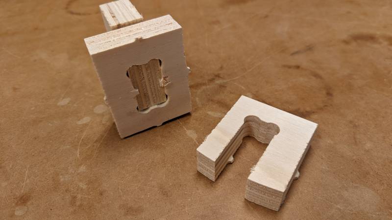
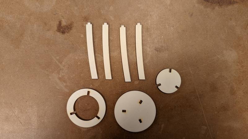
Once the job done, I immediatly tested the joints: thankfully everything fits perfectly. I just need to clean up the tabs when the stool will be done.
Assembly tests
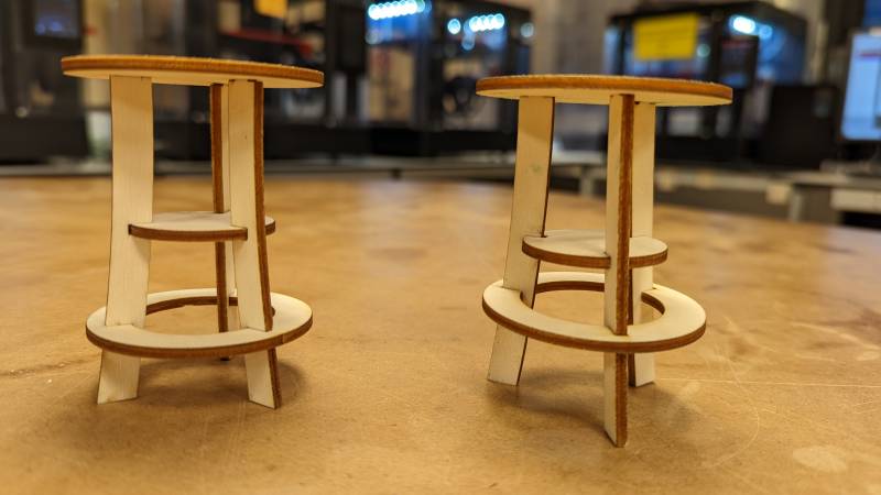
To finish the tests runs, I laser cutted two versions of the stool: one where the circles are cutted and the feet inserted in them, and one with the inverted option (where the feet are cutted to hold the circles). I’m glad I did that, because I realized the last option was the more stable one (and it is kind of important in a stool!).
You can see the better option on the left. If I may change something it will be aesthetic now I know my design is functional.
Production
I made one part of my design on a (giant) MLLaser in AgriLab and the other parts on our ShopBot (so little in comparison!).
MLLaser
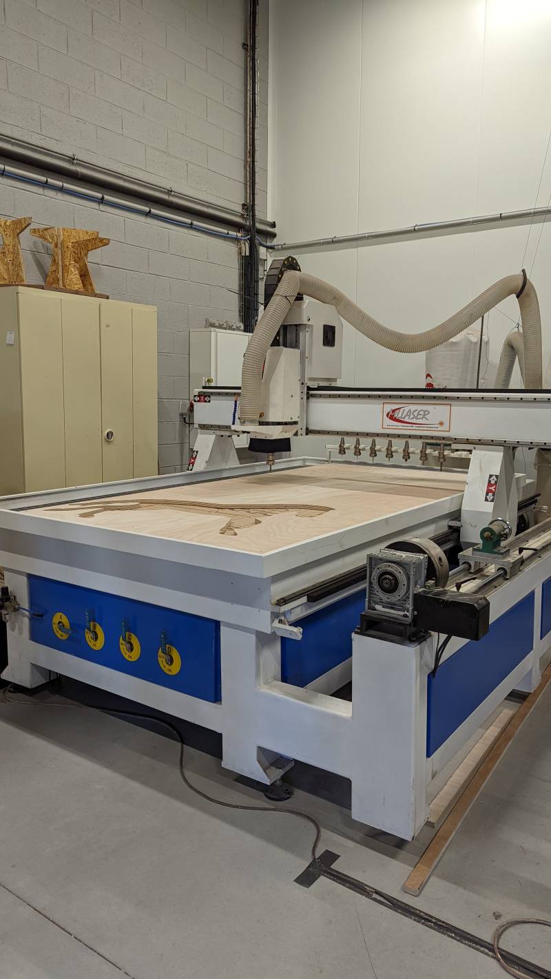
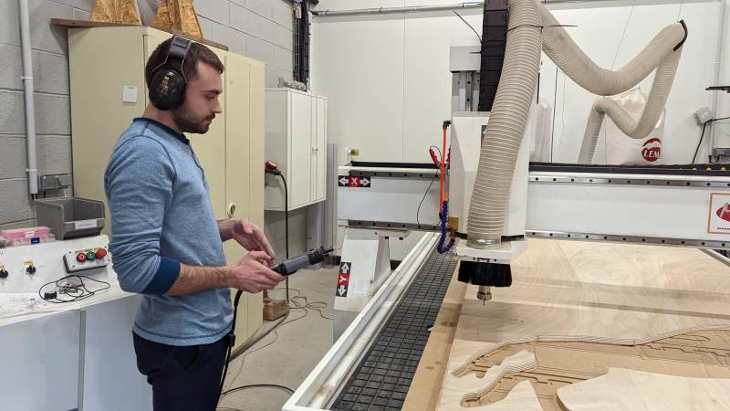
Theo was kind enough to show me how to work with the big CNC.
We first prepared the design in Fusion360 (on Theo’s computer, as I can’t use Fusion on Linux): the steps are the same as in VCarve but directly included in Fusion.
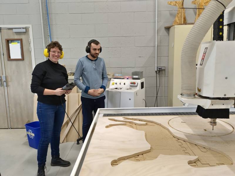
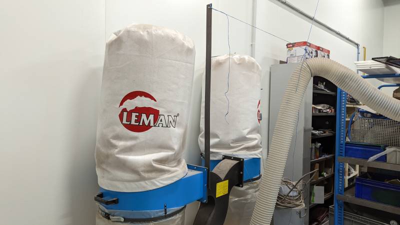
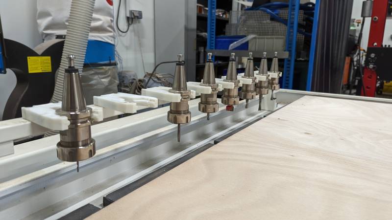
He then explained to me the safety rules specific to this machine. You can see on the pictures below there are two ventilation bags, and the machine owns a automatic endmills-changing tool.
The remote control tool is really useful, as we can move around the machine to check everything while checking the file on the screen. We zeroed the mill and started the job.
I also couldn’t resist of filming the automatic endmill change  It’s not that fast in reality, I accelerated the video: the all process is much slower (almost two minutes).
ShopBot
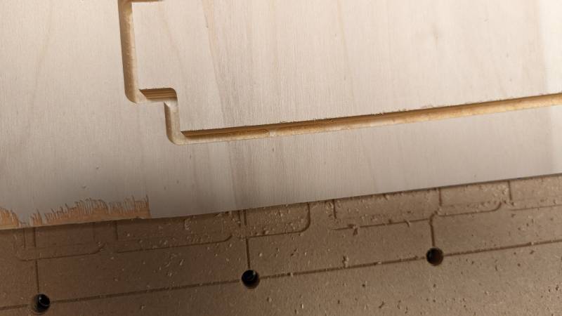
Once we were back in Sorbonne, I had to mill the rest of the design. I first used wood offcuts to waste as little wood as possible. As I wasn’t entirely sure if the design could be milled on this little space, I zeroed the mill 22mm above the plank to make a first pass in air.
You can see on the video below that I miss one centimeter to be able to make two feet on my offcut: I made only one and fetched a new plank for the rest of the design.
On a new offcut I was able to make the two other feet. I however was surprised because the endmill didn’t cut through all the material. We had to make another pass to finally cut everything correctly.
As I used a downcut endmill, the result was correct on the top of the plank but not that good on the other side. I sanded one feet and took a picture to show the differences.
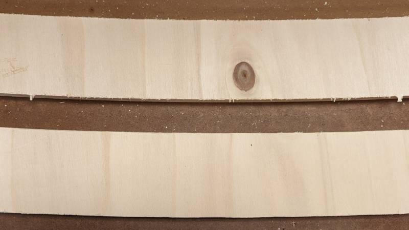
After making the feet, I discussed the all process with Stephane and we postulated this: we were able to pass a second time to cut through the all plank, and we observed that the upcut endmill was doing a better job on the bottom of the plank thanks to our previous tests. With that, we decided to test to cut two thirds of the design with the downcut endmill, and the rest of it with the upcut endmill: we should then obtain good results on all the sides of the plank.
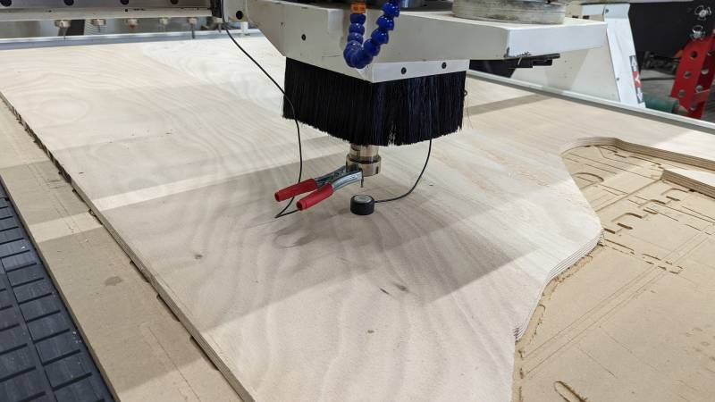
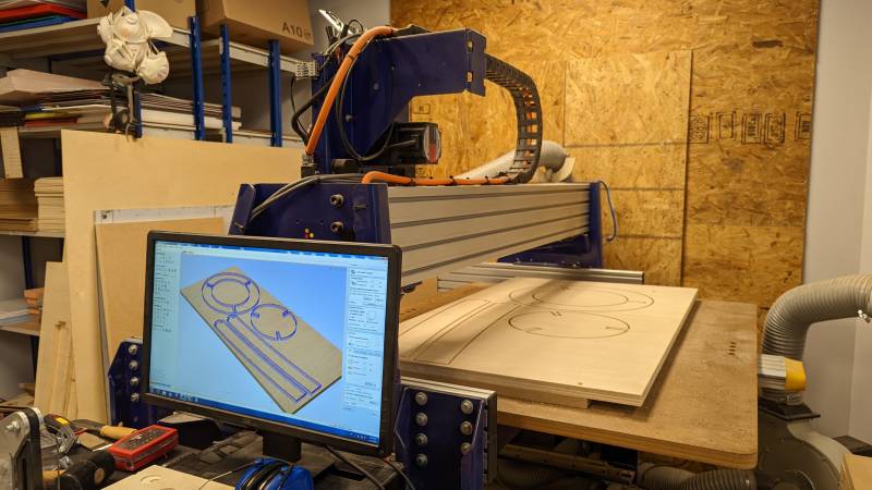
We applied this theory with the rest of the design and the results were even better than expected: I barely had to sand the parts after milling! You can see on the short video below a part just milled (I didn’t sand it at all!).
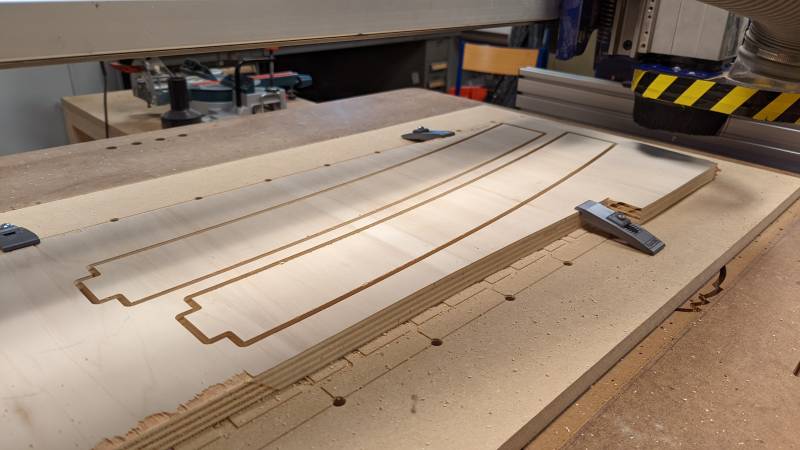
Here are a few pictures of the preparation of the design on VCarve, the workspace we worked on and the milling result!
Final assembly
It was finally time to put everything together: as I was strugling to assemble I did’nt have the occasion to make pictures (imagine me with a hammer in one hand trying to not break anything…).
I am reasonnably happy with the result: it is not as steady as I wanted, but it’s possible to sit on it and it makes a nice side table 
Files
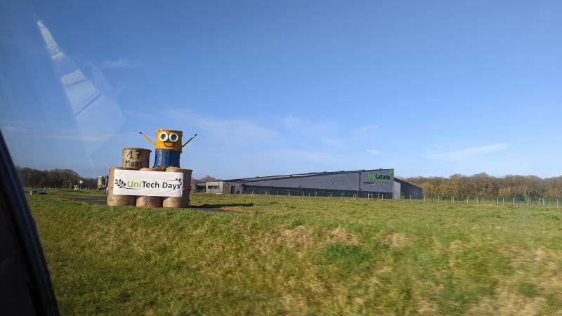
AgriLab welcomes Sorbonne
On Monday we visited AgriLab UniLaSalle It was a beautiful day: we met all the team, and particularly Luc Hanneuse and Théo Gauthier, who are responsible for the Fab Academy in AgriLab this year. Luc graduated in 2019 and Théo in 2021. They are very active in our Wednesday Regional Reviews, so I was really happy to meet them.
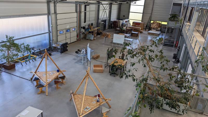
They prepared us a Fab Tour and we discovered all their dedicated spaces: 2D, 3D, Media, Data, Meca… They have a lot of spaces and use it well!
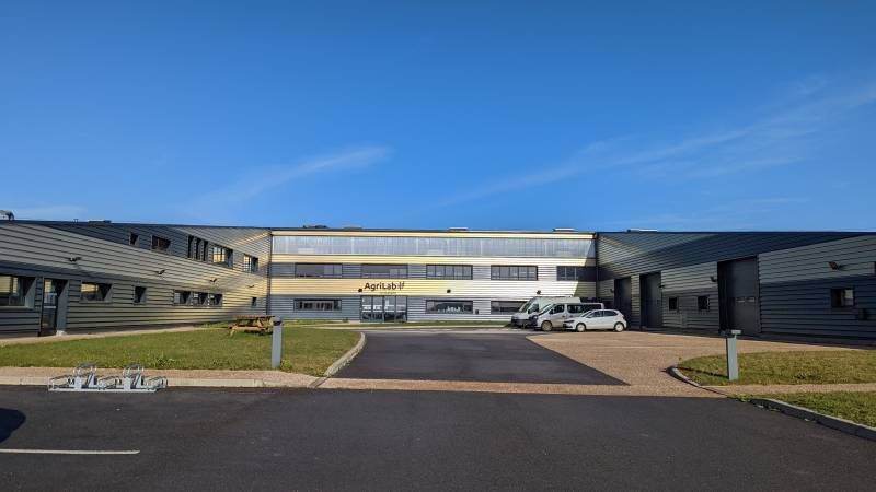
They have an enormous hall where everything is hapening: all their furnitures are on wheels to enhance mobility.
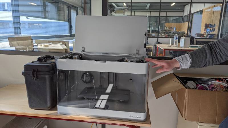
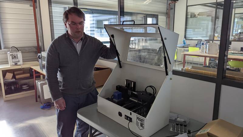
I noticed a few of their machines that we don’t have at Sorbonne: a 3D printer with carbon filament and their five axes milling machine for example.
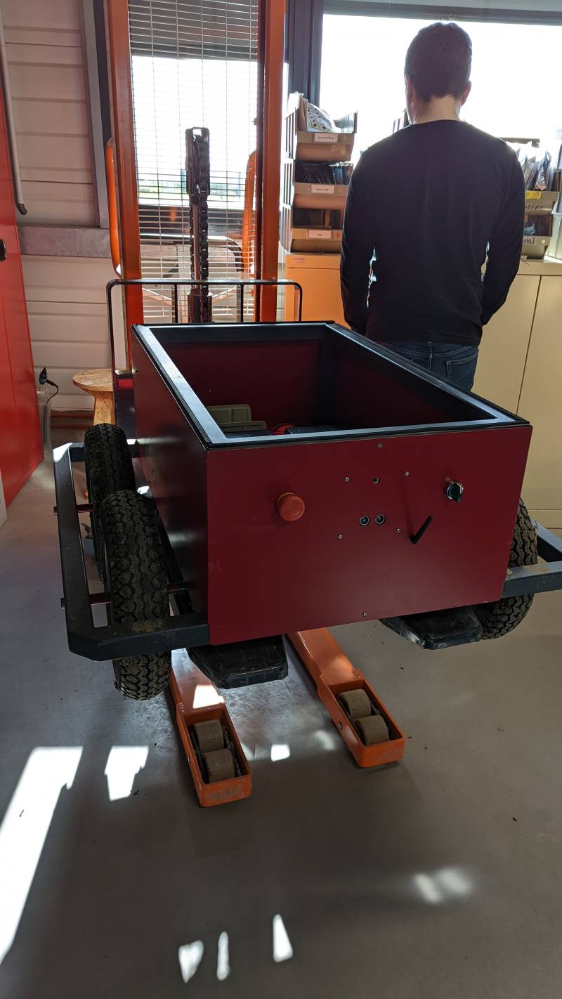
I had a look at the big something Luc made during his FabAcademy, it’s very useful for the ElectroLab!
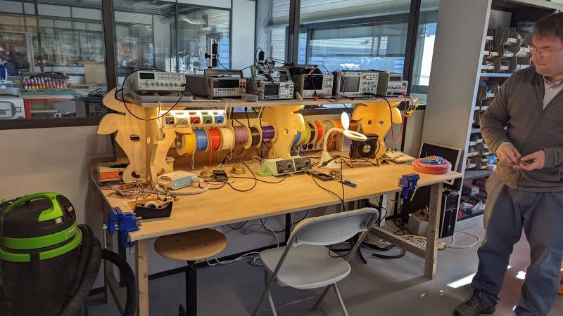
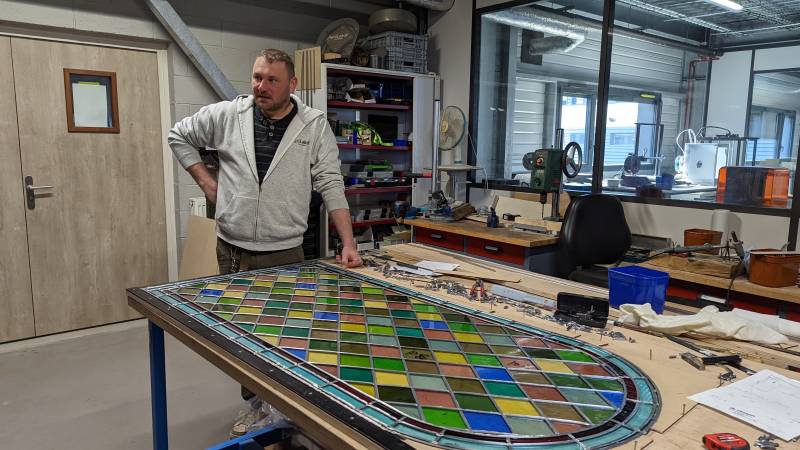
And they have an incredible space called MecaLab (the little one and the big one), where Jérôme is doing amazing work with wood and metal. On the picture you can see him working on the restoration of a stained glass window for the campus farm.
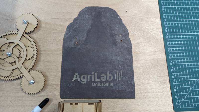
I also enjoy their idea of using different materials with laser cutter, as slate stone (we have a lot of them in Ardennes, my home region). They also show us some projects made by their students: it was really impressive to see how far can get a Lab with all these equipments!
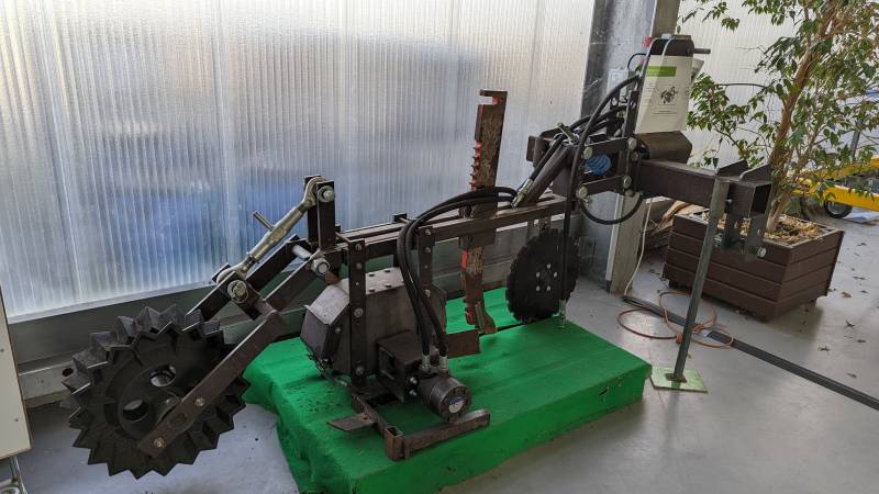
I had a peek at Theo’s final project, the Utility robot: I read his documentation before but seeing it was really helpful: I didn’t realize how sturdy it was, this is really impressive work. Theo is paticipating in a french robotic competition this week, wish him luck!
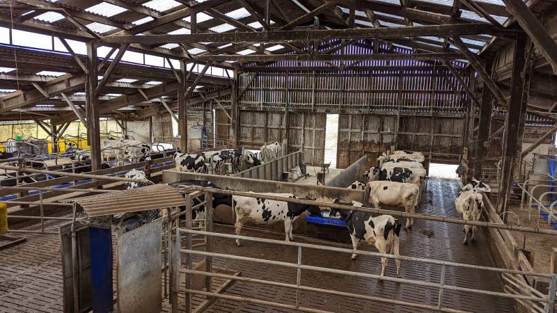
We also made a campus tour where we met the cows 
About this week
I must say: Neil was right, making something big for the first time is strangely rewarding. I can’t wait to try to make other furnitures in the future, withhopefully more sturdy designs!
As a bonus, here is a picture of the FabAcademy crew in AgriLab! We had a wonderful day and I am eager to meet other labs around the globe 
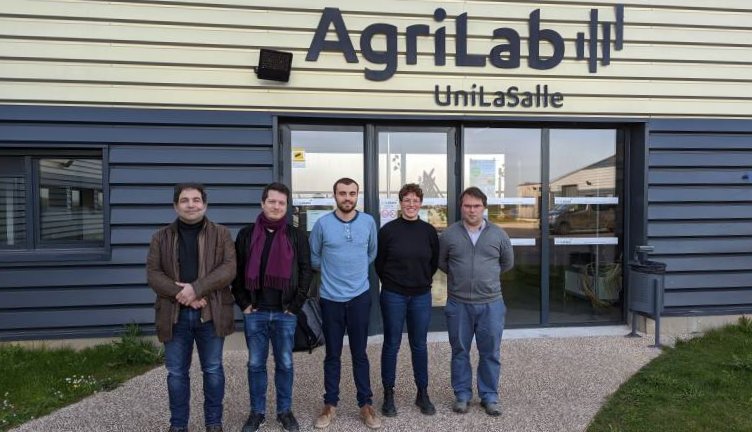 From left to right: Christian, Stephane, Theo, me and Luc.