Final Project
Welcome to my final project page.
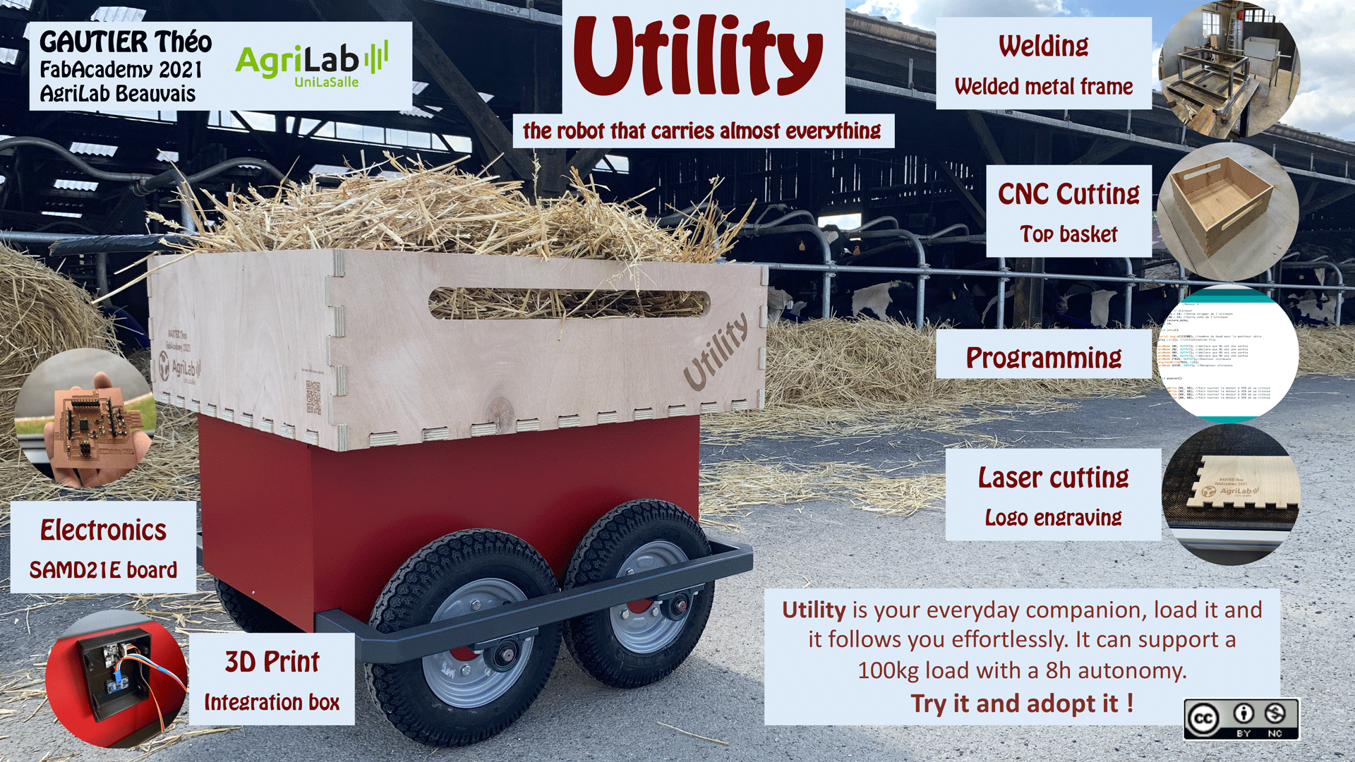
In this page you can follow all the steps to build a user tracking trolley with the capacity to carry a maximum load of 100kg.
Slide presentation

Video
Here is the final video of my project
Spiral Workflow
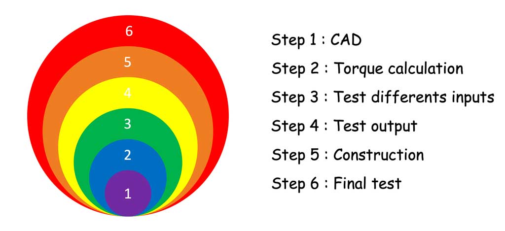
In order to achieve this project in the best possible way and to give myself objectives, I divided the work into several segments. I used the weeks to advance my final project. You can see here the evolution of my work to build my project.
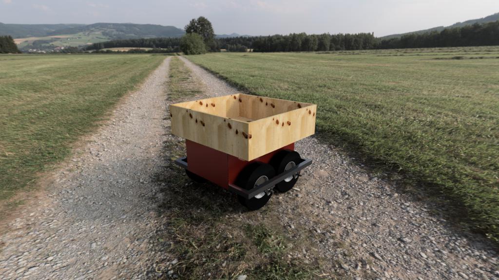
Here is a rendering made on Fusion360
Enjoy your reading

This work is licensed under a Creative Commons Attribution-NonCommercial 4.0 International License.
My first idea
As I said in my presentation, I come from the agricultural world. Regularly we have to carry heavy things. In order to relieve our health I would like to make for my final project a trolley that follows the user. Here is the first picture of my project:
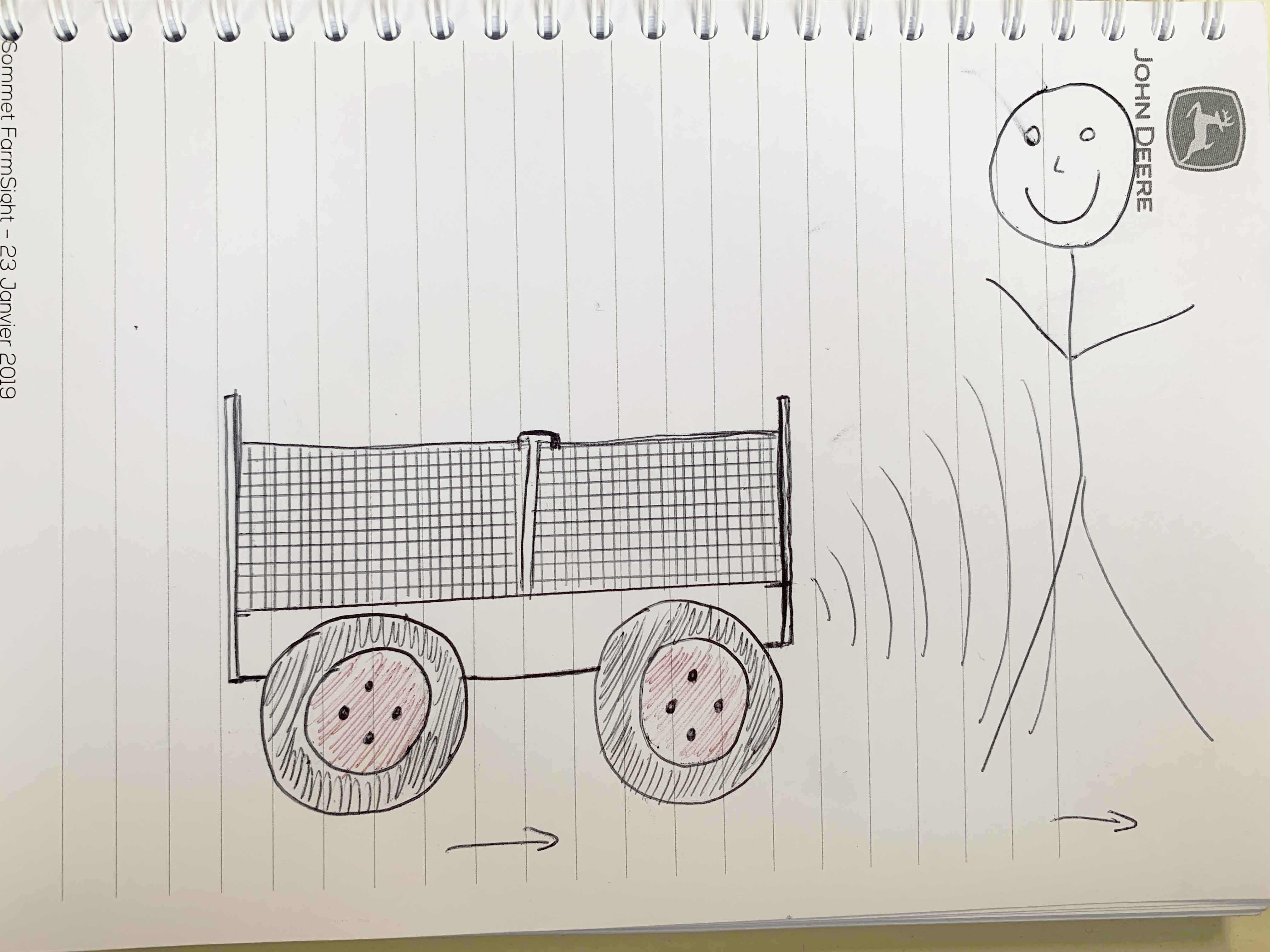
The aim is to have a box big enough to put several things on it and that without effort the user moves them from one place to another. Moreover I wanted this small robot to be able to move over several types of terrain and be able to climb a small obstacle, so one of the reflections of this project will be to dimension the size of the wheels and motors. As for the electronics, they will be hidden between the floor of the body and the axles of the trolley. The whole assembly will be made of metal.
Where did I get this idea?
The idea came when I was working with my brother. My brother was building his gate and we had to keep going back and forth to get tools from the workshop. At first we used a wheelbarrow but it was too small, so we couldn’t fit much inside it, so we had to make several trips. Moreover we loaded the wheelbarrow and it was heavy. So that day I thought it would be interesting to create a wagon big enough to store and transport tools. Then the idea that this trolley would be a follower came up in order to have my hands free.
What will it do?
This robot will help farmers to move heavy stuff without any effort on their part. My robot can carry a maximum load of 100kg. Once loaded, all you have to do is turn on the system, stand in front of the pixycam and move forward. The robot will then follow the user and you will be able to move your loads without risk to your health. Of course this robot is versatile, it can also be used for other professional activities that carry heavy loads (mason, roofer, market gardener …).
What will you design?
My wish is to design a robot that is more specialised for the agricultural world and that can move on all terrains. It will be equipped with 4 drive wheels and the whole robot will be waterproof. The possibility of changing the top platform by just unscrewing a few bolts will allow my robot to change its configuration in just a few minutes. The structure will be mainly made of metal.
About the boards, I will make the motor control board with several transistors to send the power to my motors.
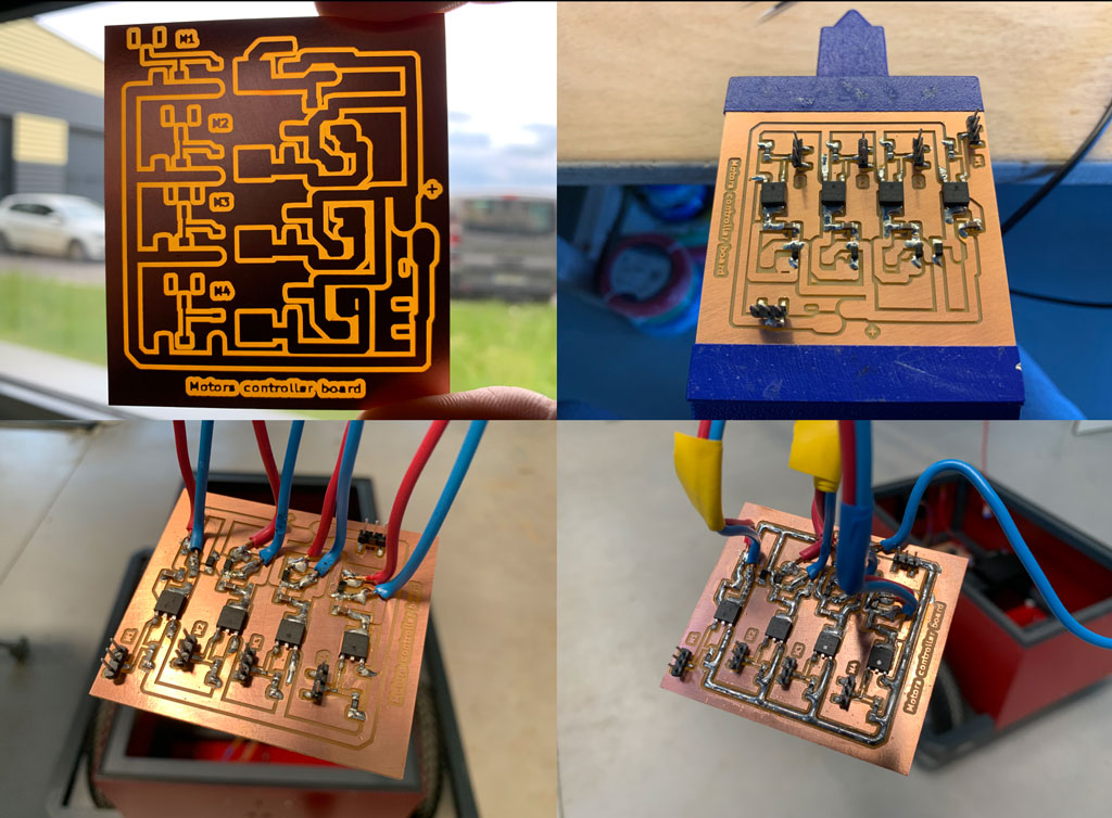
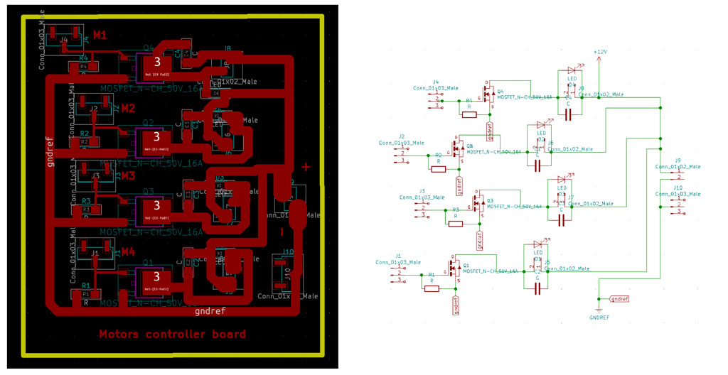 First board realized during the output week. Click here for more information on how to make this board.
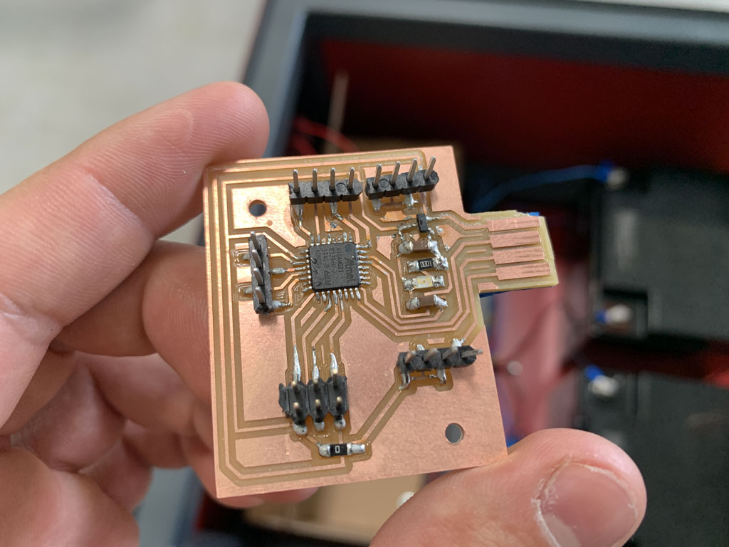
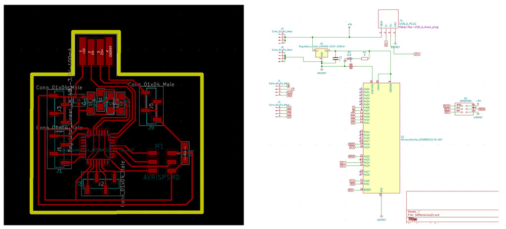
As for the microcontroller, I chose to use a SAMD21 that I have already made in the past weeks. The advantage of the SAMD21 is that it has enough memory capacity to support the pixyCam but also to control my motors and the ultrasonic sensor.
Computer Aided Design with Fusion360
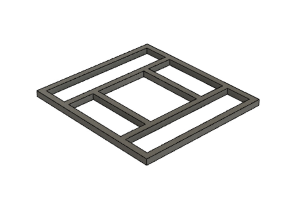
During the week dedicated to Computer Aided Design (CAD) I decided to make a 3D drawing of my future tracking robot.
I started by drawing the chassis of my robot
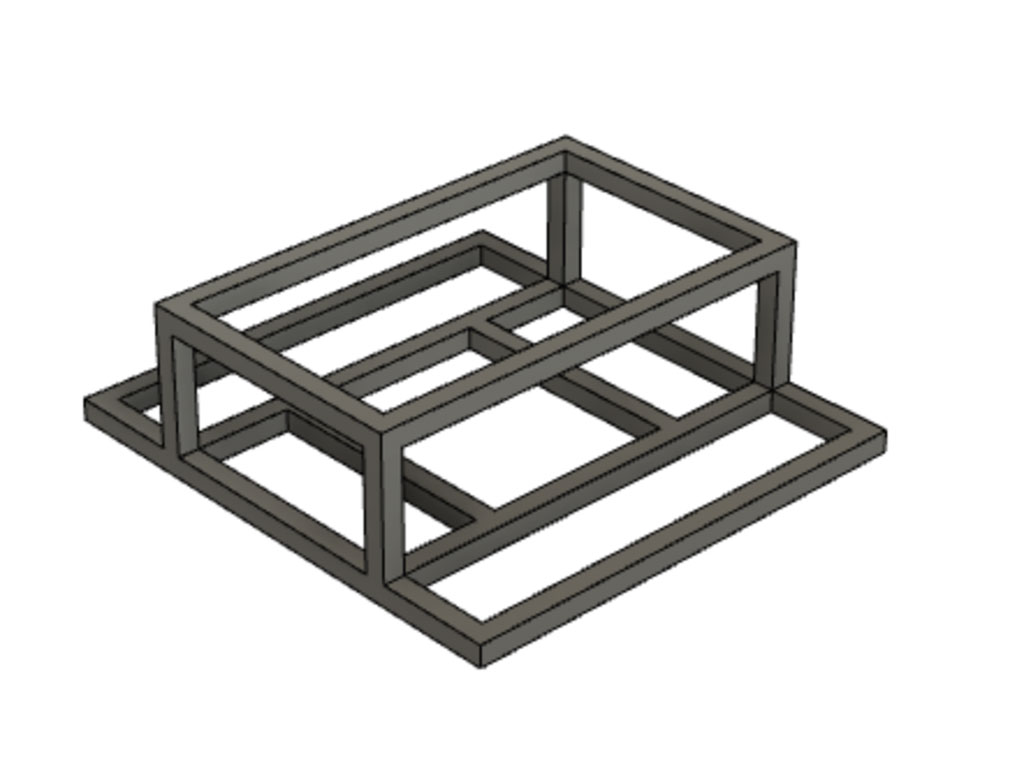
I then added the protective sheets on the sides to close the unit.
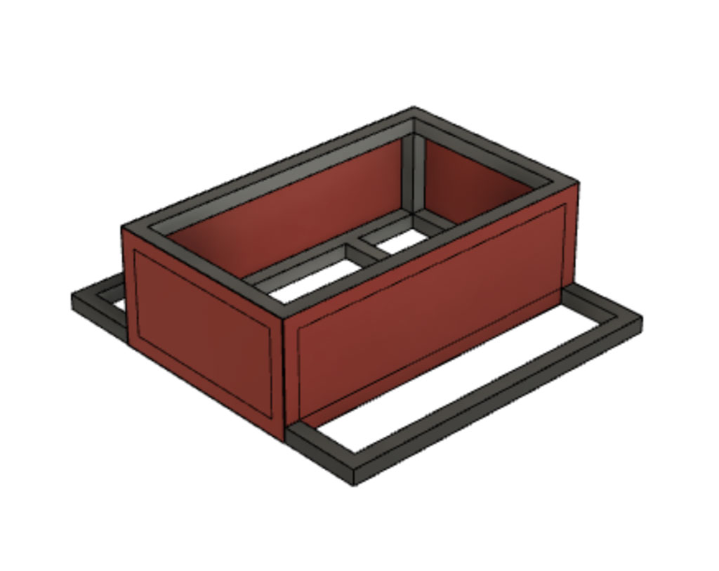
I then added the wheels with the bearings. For the wheels I drew them quickly to size and then did a copy/paste for the other wheels. Concerning the bearings I inserted a McMasterCarr component
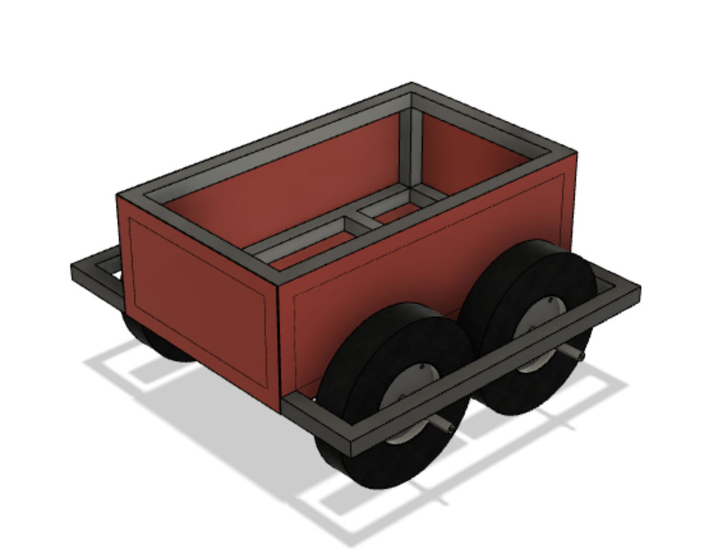
Finally I added the motor protection boxes made in week 17 to simulate the position of my motors
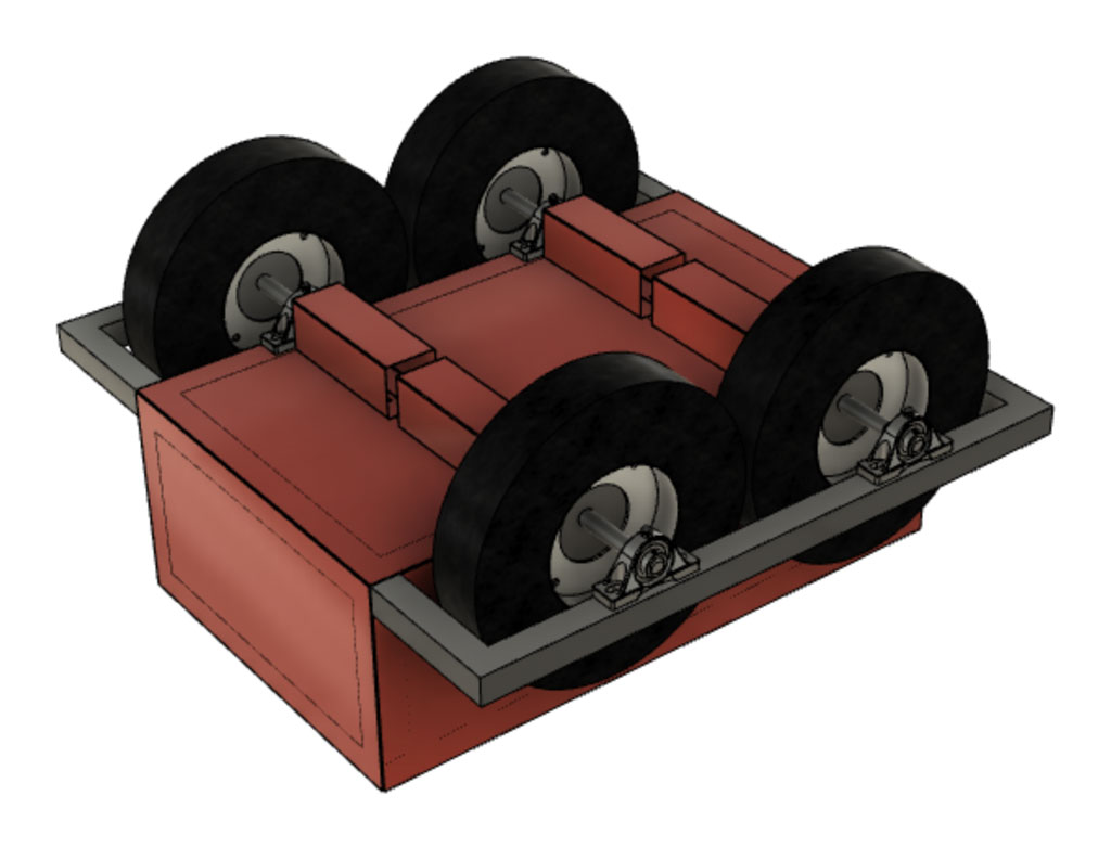
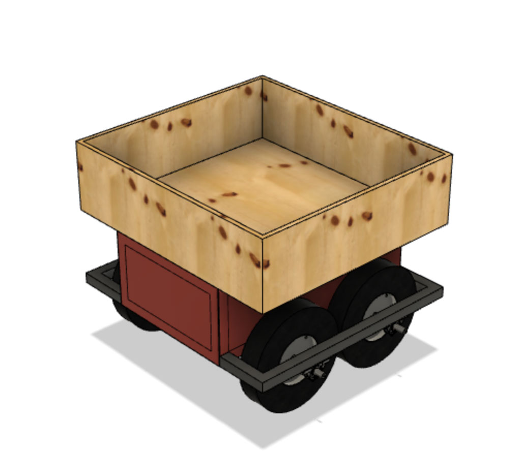
To finish I added the storage basket on top to close the set and make a quick rendering.
For more details on how to use Fusion360 to render, animate, insert a McMaster Carr component or any other details I invite you to view my dedicated page by clicking here.
Calculation of power torque
In order to dimension at best the motors that I had to use I realized a table Excel to calculate the torque. I also took the opportunity of this table to calculate the number of rotation par minute (rpm) that my engine should deliver. Here is the information that was useful to me to find the motors that were the most appropriate for my engines.
PS : I have put my Excel table at the end of this documentation. Don’t forget to accept the macros so that it is active. You would then simply have to change the values of your robot to make your calculation automatic.
| Subject | Values |
|---|---|
| Torque required for a robot carrying a 100kg load | 268,89 Nm |
| Number of rpm required for a maximum speed of 10km/h with a 38cm diameter wheel | 139,8 rpm |
The robot being 4 wheel drive I can divide the power of my motors because this one is added. For example if you want 100 Nm of power you can use 2 motors of 50 Nm because the power is added when the motors are activated. However my motors must have a speed of 140 rpm. The power can be added but if the maximum speed of my motors is only 50 rpm then I can put 4 motors, my speed will never exceed 50 rpm.
After having calculated this I had to find a motor capable of delivering a minimum torque of 70 Nm and a minimum rpm of 140.
List of materials needed
For the construction of my robot the bill therefore amounts to 700€. This price may seem expensive but it is nothing compared to the commercial solution.
Input ultrasonic sensor
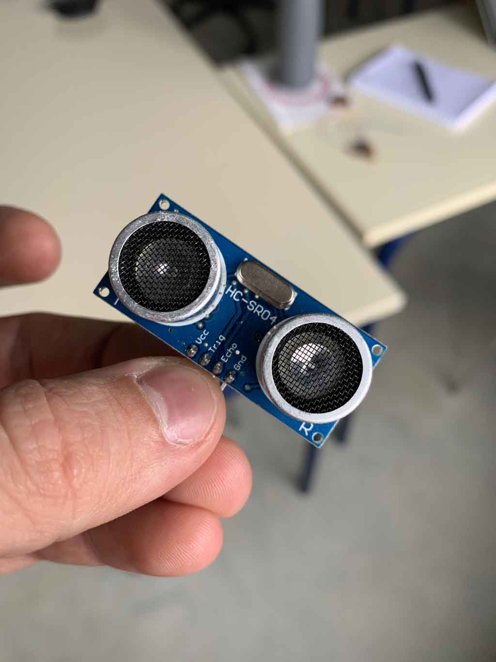
During the input week I was able to try out the ultrasonic sensor which I will use in case of an object too close to my robot. I realized several types of tests to confirm the use of this sensor for my final project. For more information on how an ultrasonic sensor works click here.
For my final project I used a HC-SR04 sensor, which works with a 5 volt supply, has a measuring angle of approx. 15° and can measure distances between 2 centimetres and 4 metres with an accuracy of 3mm.
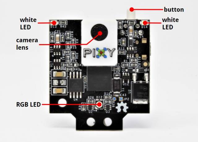
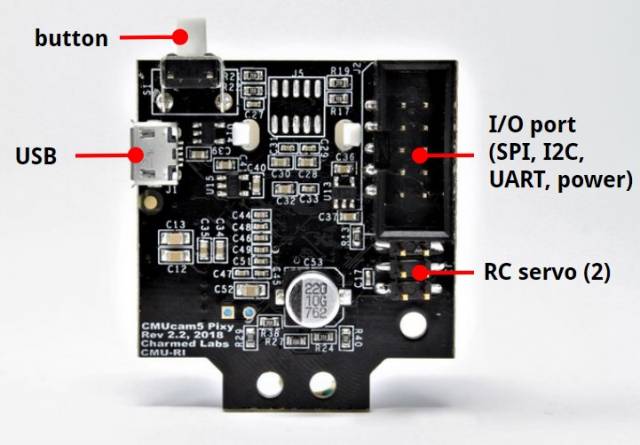
Input PixyCam2
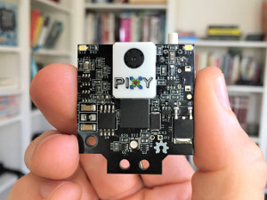
PixyCam is a camera that is able to recognize objects, colors, barcodes, lines… and send coordinates to the microcontroller. I used this kind of camera to detect the red color (color which is more difficult to find in nature than green or blue, you can of course set another color) which then sends the coordinates of my user to the SAMD21E which then corrects the trajectory of my robot
Datasheet PixyCam2
- Processor: NXP LPC4330, 204 MHz, dual core
- Image sensor: Aptina MT9M114, 1296×976 resolution with integrated image flow processor
- Lens field-of-view: 60 degrees horizontal, 40 degrees vertical
- Power consumption: 140 mA typical
- Power input: USB input (5V) or unregulated input (6V to 10V)
- RAM: 264K bytes
- Flash: 2M bytes
- Available data outputs: UART serial, SPI, I2C, USB, digital, analog
- Dimensions:1.5” x 1.65” x 0.6”
- Weight: 10 grams
- Integrated light source, approximately 20 lumens
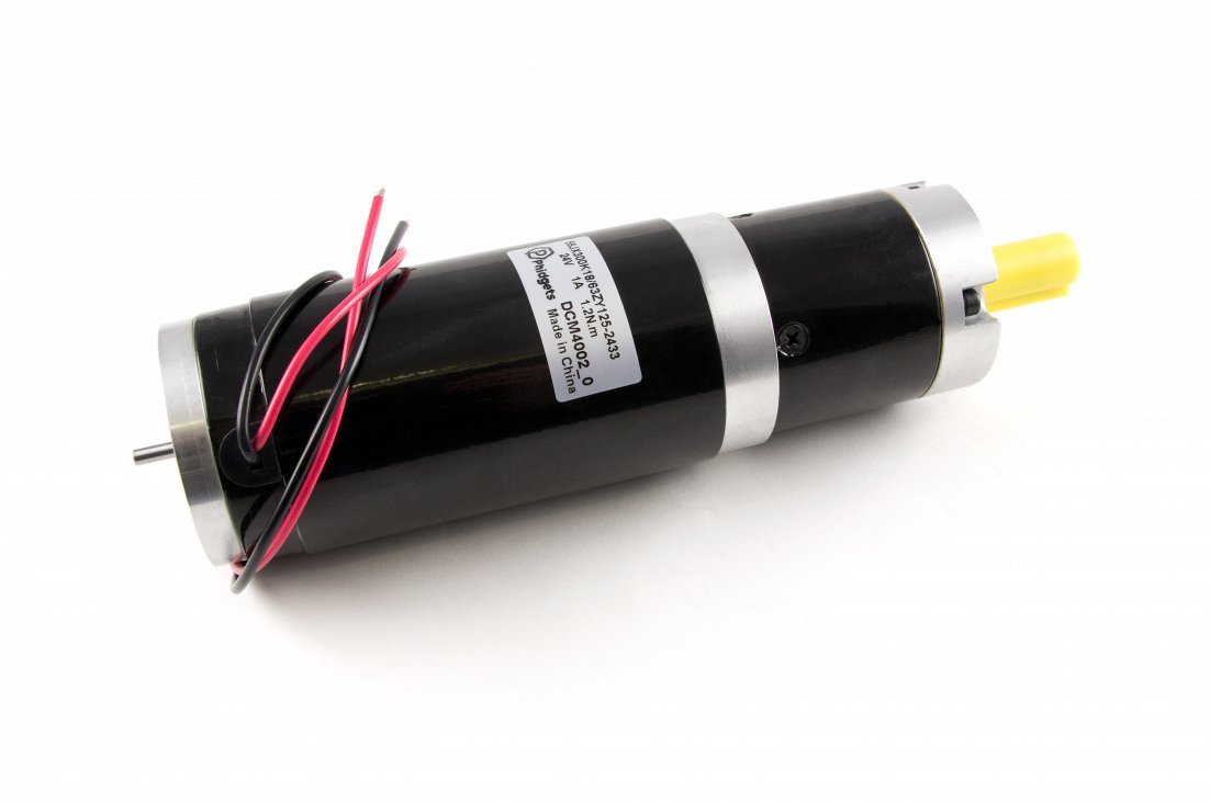
Output motors
After calculating the torque I needed for my robot I had to find the right motor for my needs. I found this motor which has a high torque and a low axis rotation. This motor will allow me to move my robot despite a heavy load on top. I found this engine on the Phidgets website.
Datasheet motor
| Motor Properties | |
| Motor Type | DC Motor |
| Output Power (Mechanical) | 100 W |
| Rated Speed | 182 RPM |
| Rated Torque | 47 kg·cm |
| Stall Torque | 267.7 kg·cm |
| Electrical Properties | |
| Rated Voltage | 24 V DC |
| Rated Current | 6.5 A |
| Stall Current | 22 A |
| Physical Properties | |
| Shaft Diameter | 12 mm |
| Wire Length | 300 mm |
| Weight | 2,1 kg |
| Gearbox Specifications | |
| Gearbox Type | Planetary |
| Gear Ratio | 18:1 |
| Number of Gear Trains | 2 |
| Maximum Strength of Gears | 25 N·m |
| Backlash Error | 3° |
| Customs Information | |
| Country of Origin | CN (China) |
Prototype development
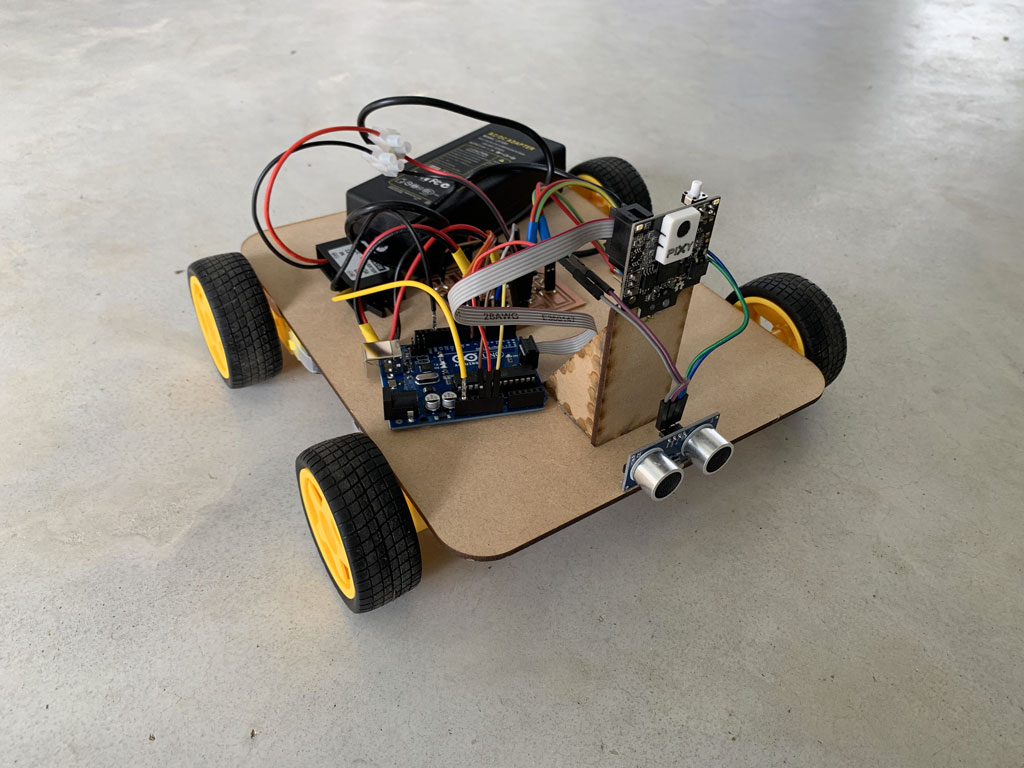
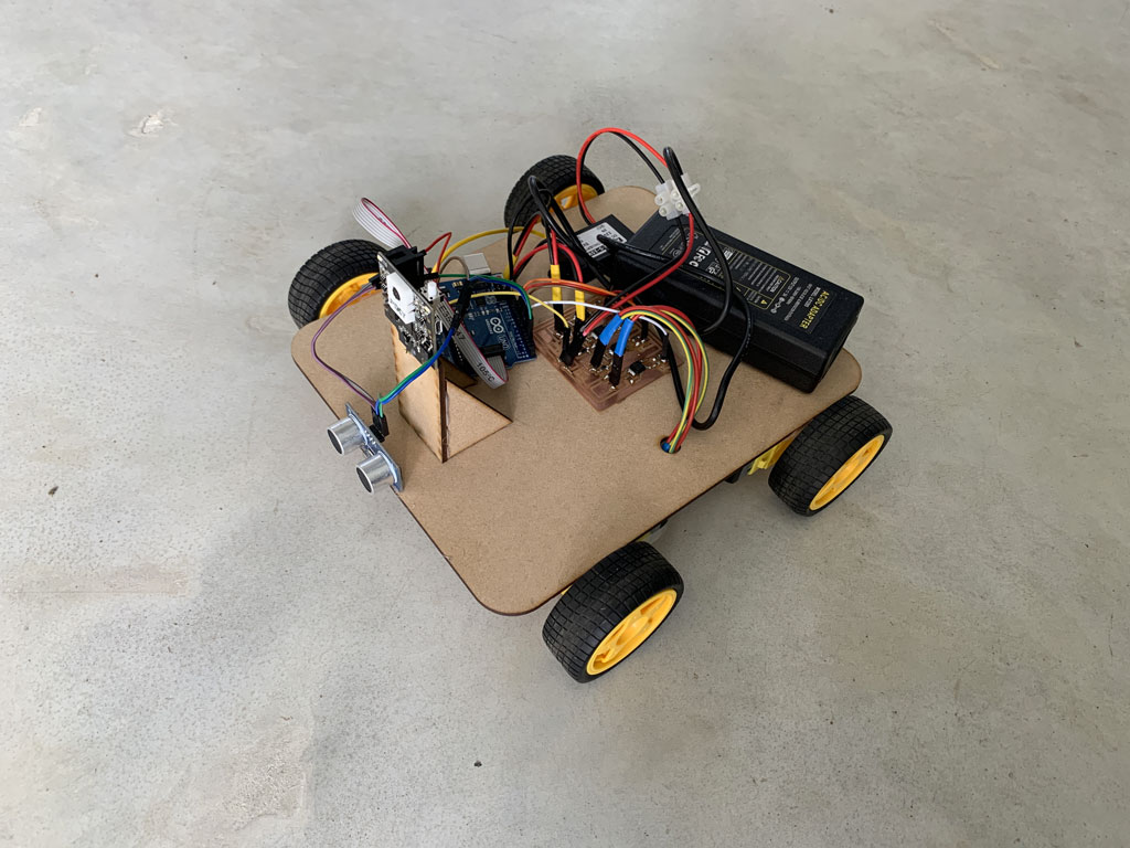
Before starting my project I made a small quick prototype to check the reliability of the code and to see what improvements I could make.
So I laser cut the base of my prototype with the support for the Pixy2 camera. Then with hot glue I glued the small motors I used during the output week, the sonar discovered during the input week and the Pixy2 camera with its support.
Concerning the management of the engines I used the power board I created during the output week. For the power I used a wired power supply. The batteries present at AgriLab are much too big for my little robot so to avoid a too important weight constraint I decided on a wired power source. If you want to rebuild this robot it is possible to use a battery instead.
Finally for all the code testing I used an arduino UNO. The communication between the camera and the Arduino is done through the SPI socket.
List of materials for the construction of the prototype
- A 3mm MDF for the base
- 4 motors like this one
- 4 wheels which are supplied with the motors to transmit power to the robot and make it move
- 1 sonar HC-SR04 to detect if an object is near the robot and prevent collision
- 1 pixyCam2 to detect the colour to follow and send the coordinates to the arduino
- 1 Arduino Uno to interpret all the data received and to send a previously recorded response
- A 12V - 5V converter to power the Arduino
- A motor control board to send power to the motors without going through the Arduino
- A power source to supply electricity to the robot
- Connecting wires to link the elements together and ensure good information transmission
- Hot glue to fix all the elements
The camera sends the coordinates of the detected object to the arduino, which then performs the functions defined by the positioning of the object in front of the robot. Of course if an object is too close to the robot or if the robot does not detect the colour to follow then it stops.
Video test
Construction
For the construction I decided to do it in the workshop of the farm because it was easier for me to make it at home. For this I used several machines which will be detailed when I use them.
Tubes cutting
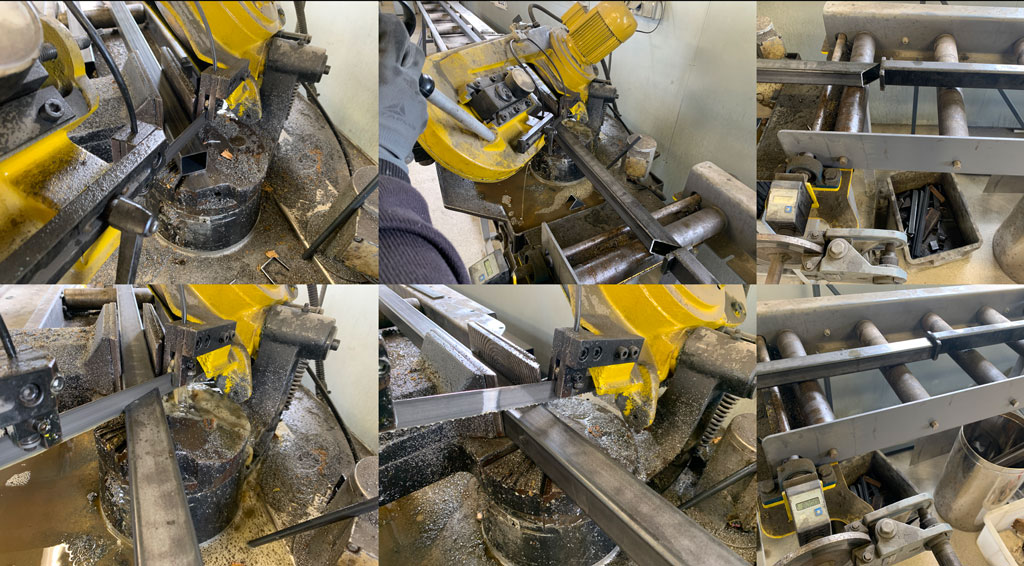
In order to start my robot I decided to start by making the frame. For that I used 2 bars of 6m of metal with a dimension of 40mm x 40mm in thickness 2mm. I chose these bars for two reasons, we have plenty of them at the farm and they are solid. I then cut them to size. For this I used the digital stop that we have. This stop makes it possible to have very quickly, simply and precisely the exact length of our cuttings. To make the frame I also made cuts at 45° to make a nicer and stronger joint. To do this I placed our band saw at the desired angle and cut the tubes.
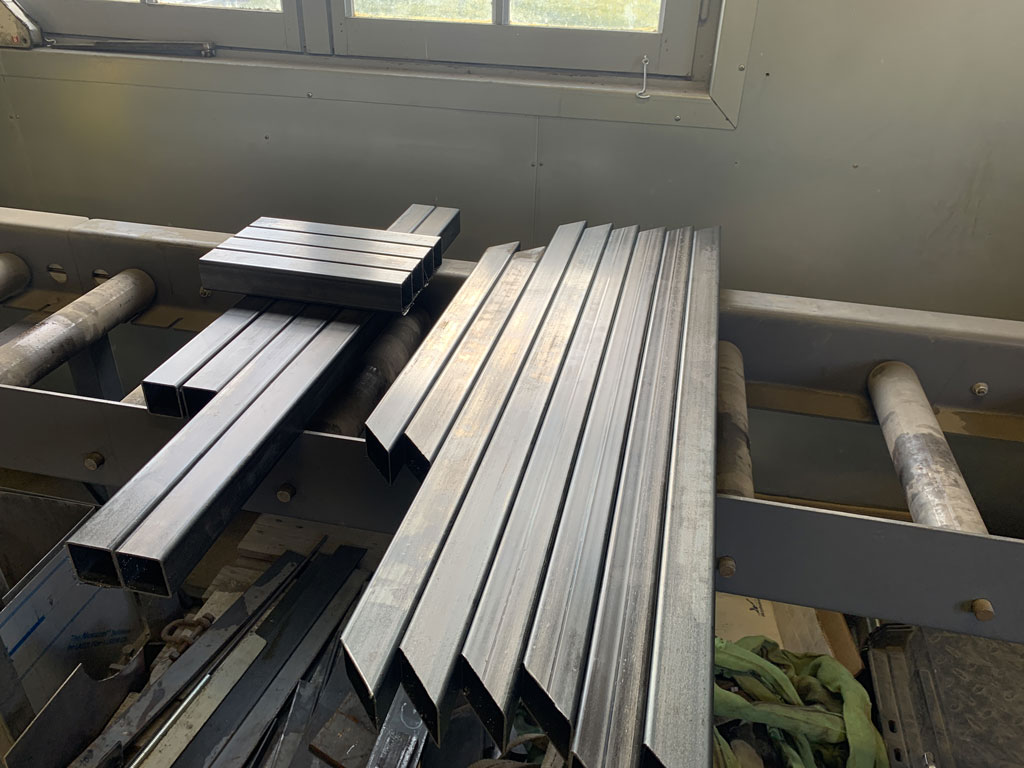
Here are all my tubes once cut with the band saw seen before.
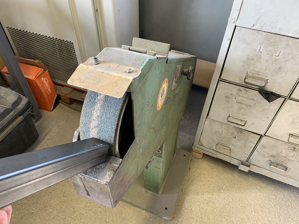
Deburring
Once the cuts have been made with the band saw and the digital stop, it is best to deburr the tubes. During the cutting process there may be some very sharp pieces of metal left on the cut. To avoid any risk of injury I deburred all the tubes with a belt sander.
Welding
When all my tubes were cut and deburred I could start positioning them for welding. To do this I used a MAG (Metal Active Gaz) welding machine. This type of welding is easier and stronger than arc welding. I started by welding the corners of my frame very slightly.
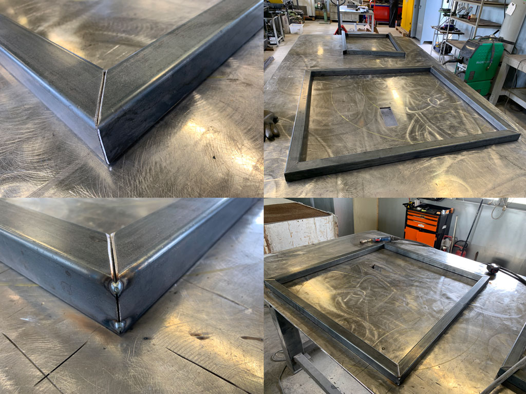
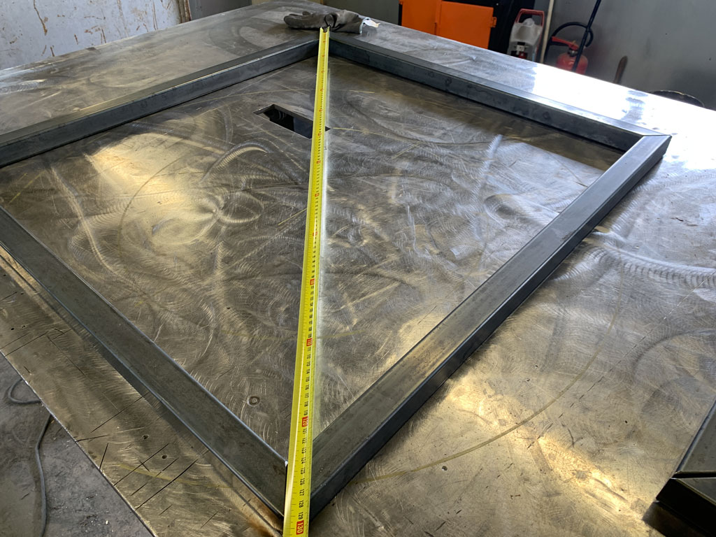
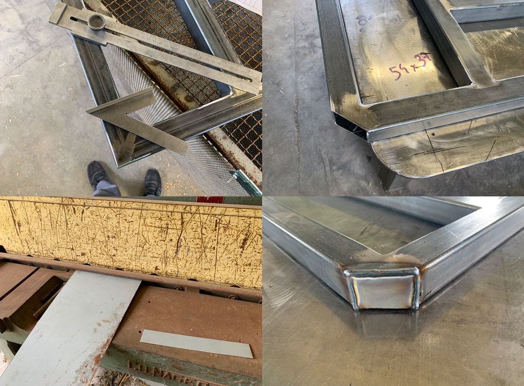
Knowing that welding makes the metal work a lot I checked the squareness by taking the distance of the diagonals. Checking the length of the diagonals is more accurate than using a bracket.
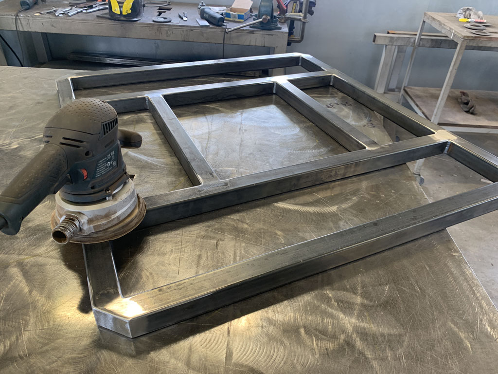
When all the checks were done I welded my entire frame together and then sanded the welds with a grinder. I decided to sand the welds to make them almost invisible on the visible sides for aesthetic reasons.
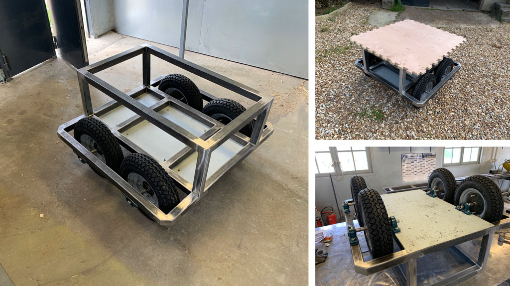
I then placed my tubes inside. These tubes will be used to support the motors and the bearings for the wheel axles.
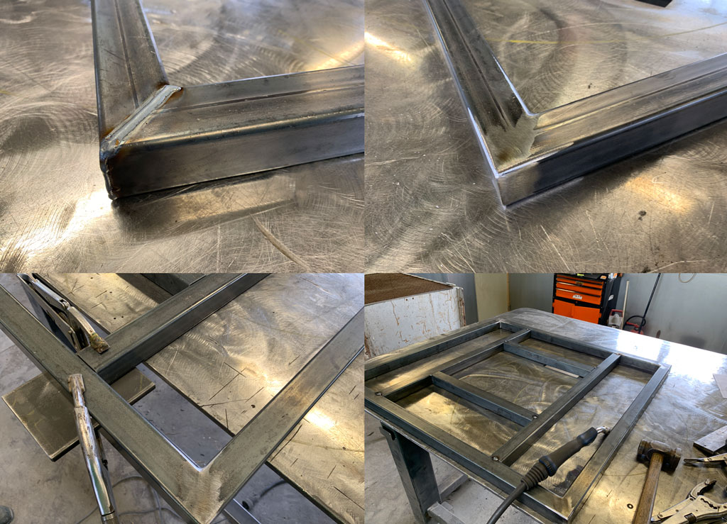
I then welded everything solidly and also soldered the top of my chassis. When all the soldering was done I sanded it with a grinder and to get a smoother finish I used an eccentric sander with a very fine grit (120) to make it look soft and pleasant to the touch.
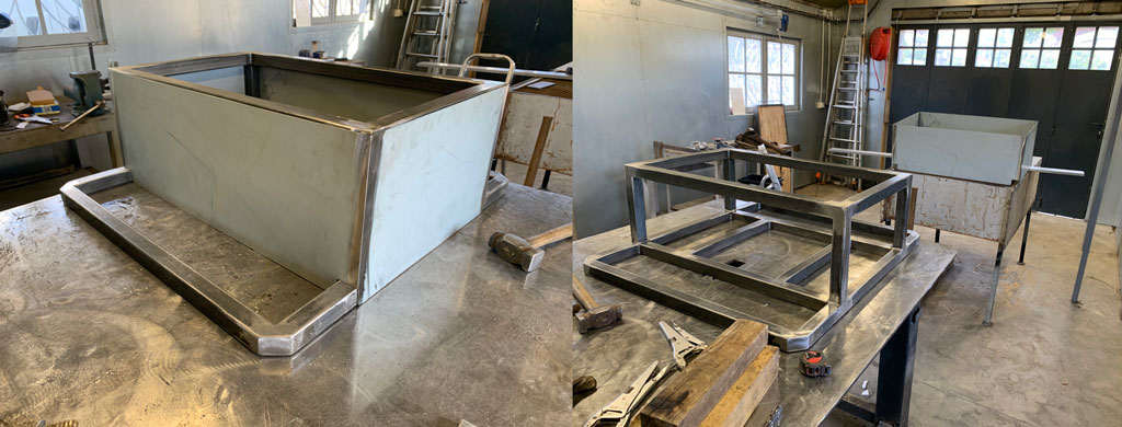
In order to limit the risk of injury, I have cut the corners so that they are less dangerous in the event of a collision. To do this I cut the angle with the grinder. I then added a small piece of sheet metal that I cut with a shear.
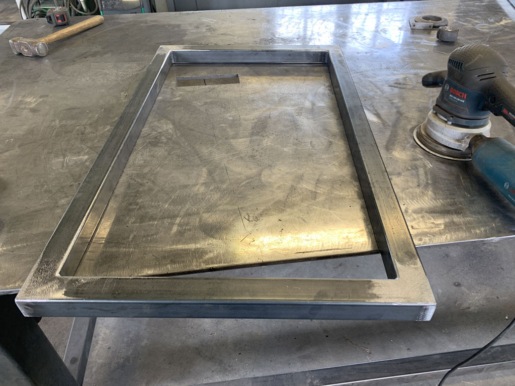
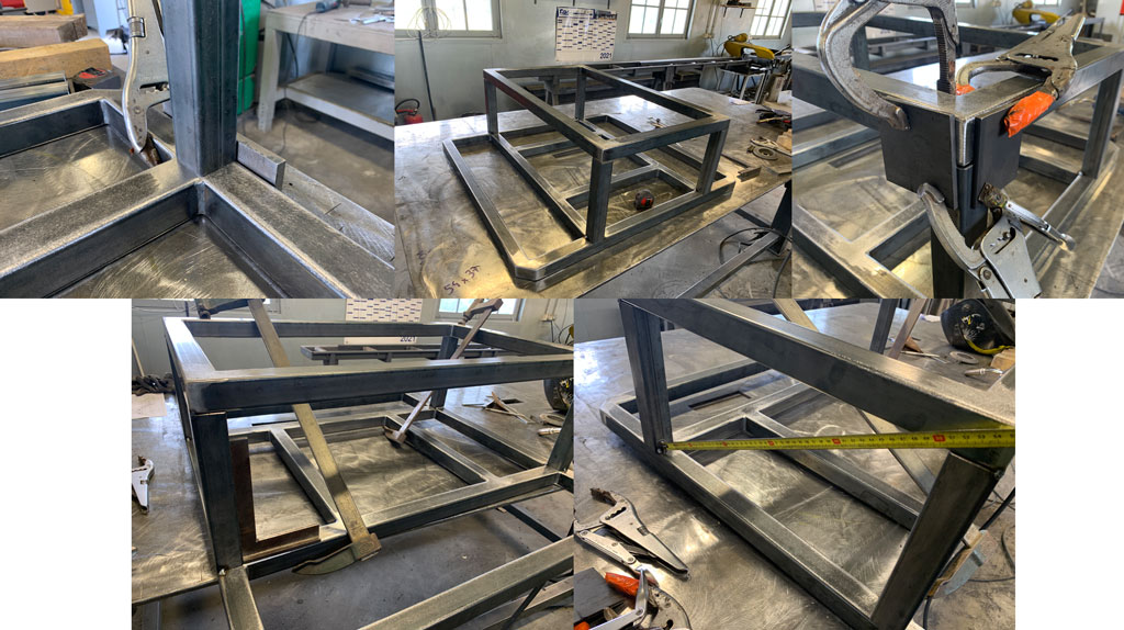
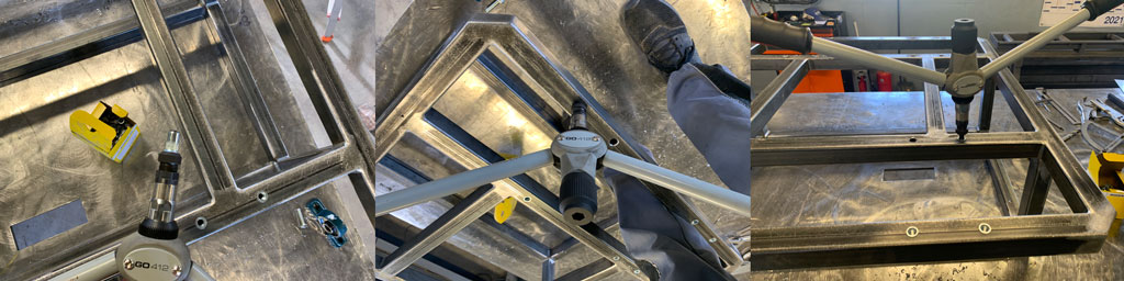
Once the finishing touches were done I did a final check on the squareness of my frame. With the welding my frame had moved a lot in some places. To check the flatness of my frame I used a ruler that I positioned in several places to see if I needed to make any changes. After checking I noticed that my frame had moved a lot with the welding so I had to use a big hammer to rectify the mistakes.
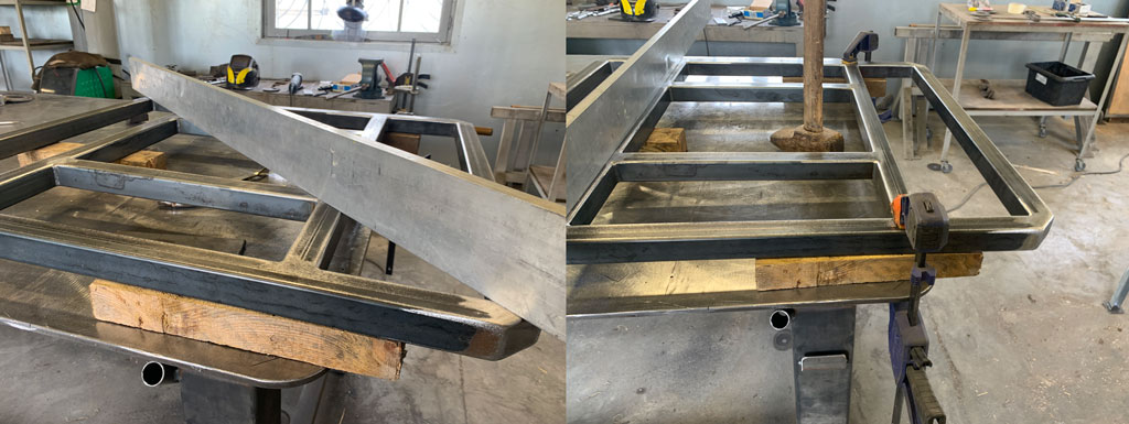
Once my frame was rectified and straight I positioned the top of my frame to be fully soldered. To align all my tubes together I used metal shims and vice grips. Once pointed I clamped all the diagonals with clamps to prevent my frame from moving again with the welds.
Tip: check your diagonals very regularly as this operation causes a lot of deformation of your frame.
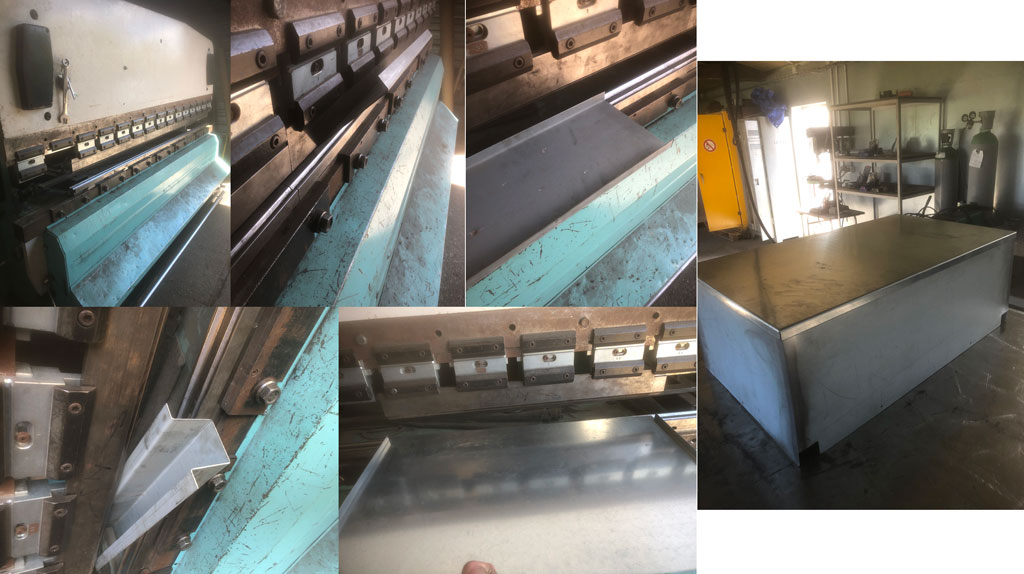
Production of protective casings
In order to close my robot on the sides I used 1.5mm thick metal sheets. To cut this I used a machine called a shear. This machine is a big chisel that is able to cut metal. Our very old but perfectly working machine is able to cut a 4mm thick sheet of metal over 2m. I used this machine to cut my sheets which will be placed on the side of my robot. Once cut I placed them on the side of my frame and put some paper to add a bit of clearance, then welded the whole thing together. This allows me to have a removable protective shell that can be positioned around my frame. This also allows me to have something waterproof, as my robot is designed to move around outside, it is important to pay attention to the permeability of the materials used.
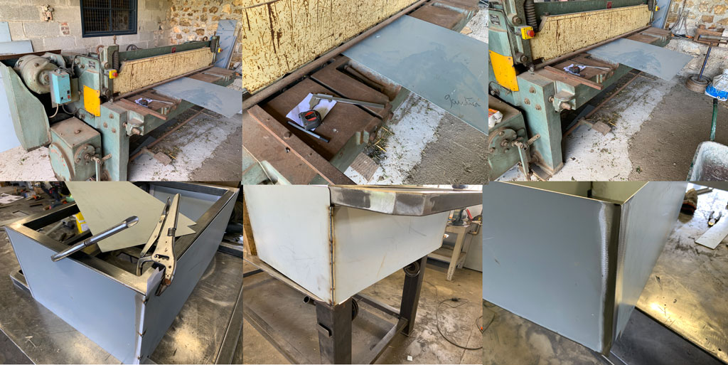
Concerning the sheet metal below the robot, I chose to screw it down and make it removable. I cut this sheet with the shears seen previously
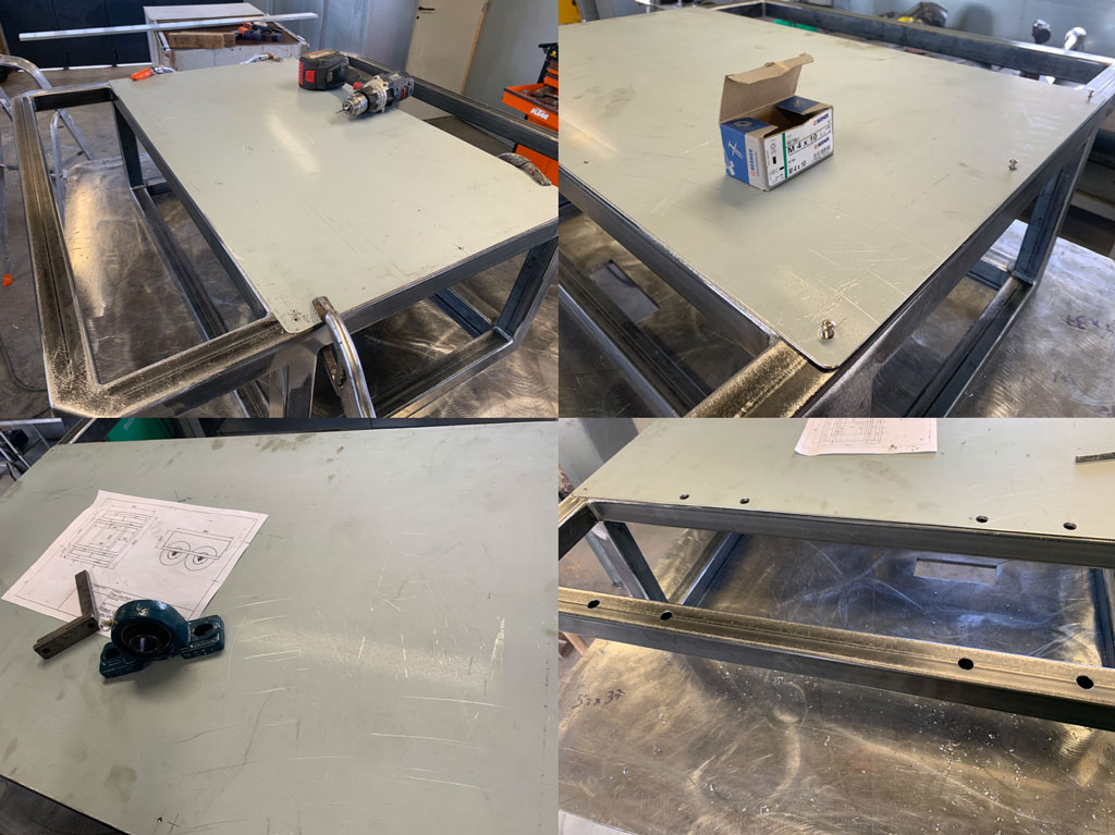
For the bearings I decided to screw them into the tube. But the tube is only 2mm thick, so it’s not possible to tap inside and make it solid. So I inserted inserts to screw the screws in places where it is not possible. To do this I used an insert pliers to crimp the inserts onto the tube.
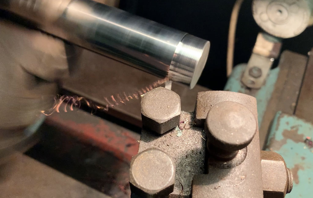
Making the wheel axles
To make my wheel axles I used a metal lathe and a jigsaw.
As I only have 30mm diameter axles I had to use a lathe to cut them down to the desired diameter, 20mm. For this I used the old lathe we have at the farm. I also decided to make a hole in the centre of my tube on one end to insert my wheel axle. I used the lathe again to drill this 12mm diameter hole.
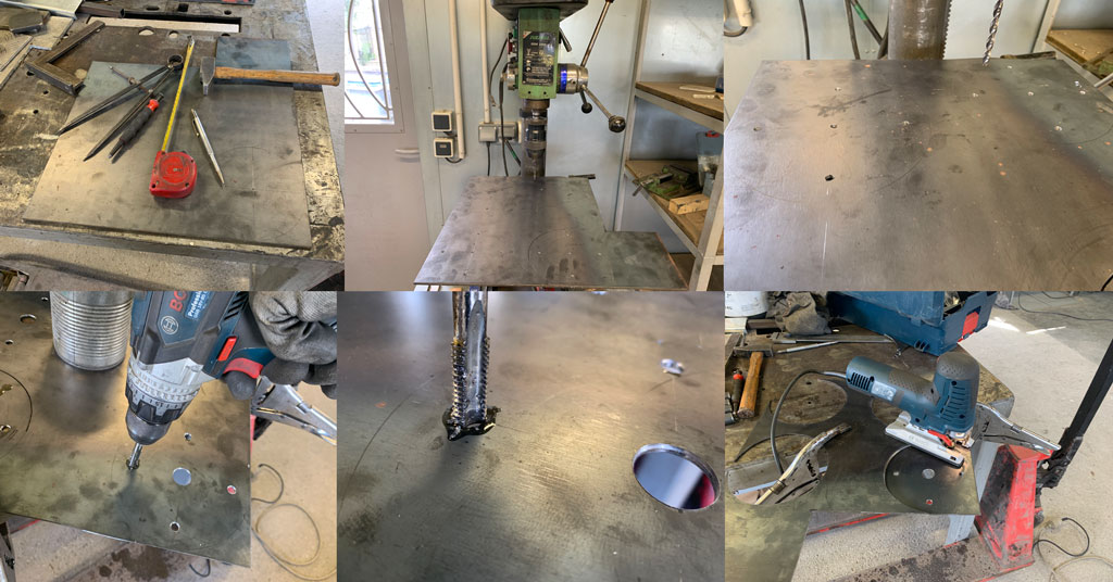
For the wheel supports I used a jigsaw and a piece of 4mm sheet metal. I started by tracing the outer circle with a compass. Still using the compass I also traced my wheel mounting holes. When I had finished with the tracing I used a punch and hammer to mark the location of my holes to be made with the drill column. I then drilled my holes with the drill press. Once my holes were finished I tapped my wheel mounting holes with a tap and a drill.
It is necessary to be very careful during this operation, the taps being very fragile, it is common that it breaks. It is also preferable to add a lot of oil to limit the wear of the taps which is expensive.
The last step was to cut out my fixing supports with the jigsaw, following the tracing line.
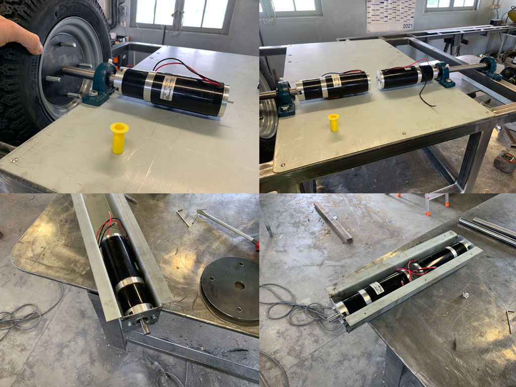
Installation of motors and creation of the engine casings
I then positioned the bearings, wheels, axles and motors to check that everything fitted together perfectly. After checking I had to modify my engine cases that I had made in week 17. For a question of ease I preferred to start again from scratch to recreate the box. So I used the hydraulic bending machine we have at the farm to make my box. It’s an old machine but it works perfectly, precise and easy to use. Once the box was bent I soldered the pieces of sheet metal previously made to fix my engine.
Assembly V1
Before painting my robot I assembled the whole robot to check that it ran well and that there were no major defects that would prevent it from working.
Painting
It is well known that what makes an object beautiful is its final result. So I decided to paint my robot. The painting allows to give a finished aspect to my prototype. For that I decided to use a grey anthracite paint for the chassis and for all the dismountable parts, I painted it in red. I really like this mix of colours. I used a spray gun for this step. For ease of use I hung the parts with wire to paint them evenly and easily.
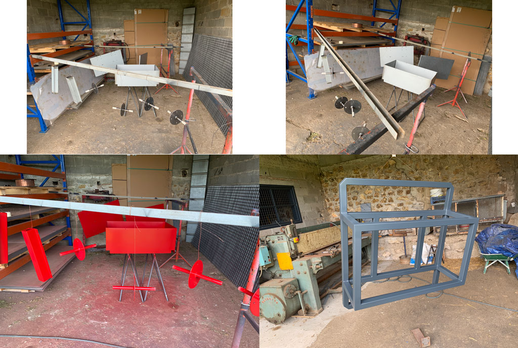
I know it’s not the best place to paint with a spray gun but as surprising as it may seem there was no dust that stuck.
Making the basket
While waiting for my painting to be done, I took the opportunity to make the basket that will be on top of my robot and that will allow to store the objects. For that I made my plan on Fusion 360 that I then exported the G code to be able to machine it with the CNC.
For more information on how to use fusion to export a G code for machining click here.
For this basket I decided to use 18mm thick okoume special exterior. As my robot is meant to go outside it was preferable to use water resistant materials.
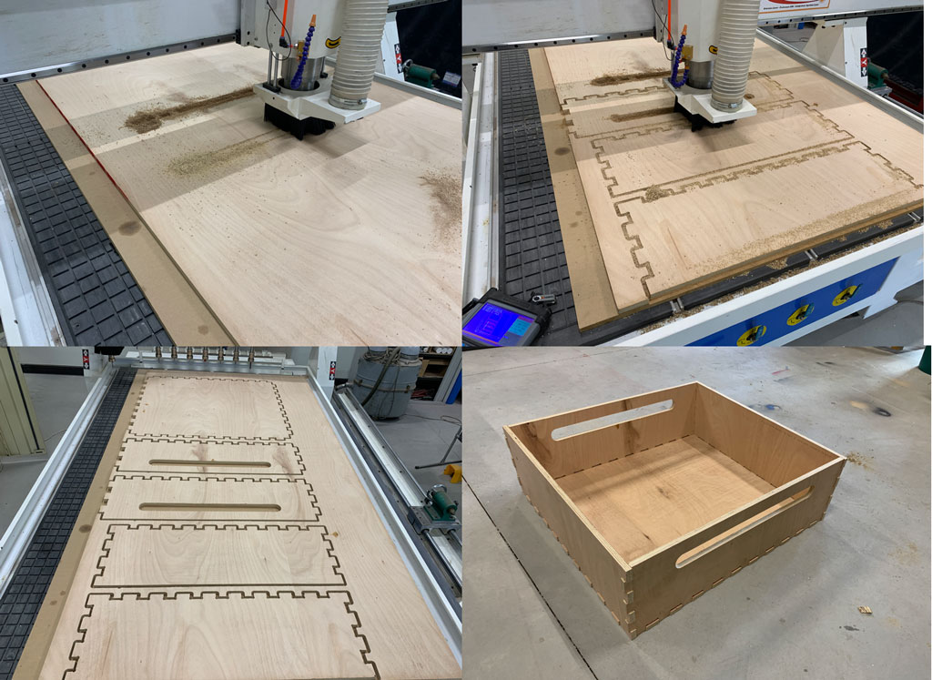
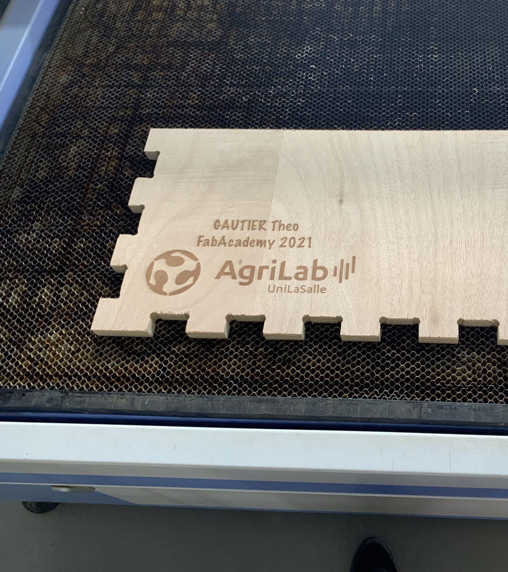
Because I still have some time left I decided to engrave my box with the laser cutter. For that I engraved the name of my future robot “Utility” as well as my name, the AgriLab logo, the year of manufacture and the QR code which directs directly towards my documentation of the final project
Final assembly
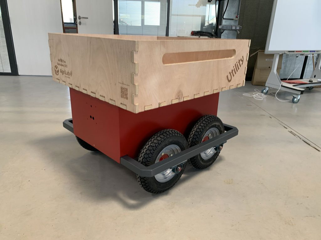
This is my final project when finished. Now it’s time for the tests!
Electonics
Concerning the electronics I used a board with a SAMD21E that I designed myself. To drive my wheels and therefore my motors I designed a board with several transistors. The transistors I chose are the biggest available in the FabAcademy inventory and have a capacity of 50V and 16A. These transistors cover my needs to drive my motors. My engines are only 24V and 6.5A. Finally a communication through the SPI port of the SAMD21E and the pixyCam allows the robot to be directed to follow the user. The pixyCam sends the coordinates of the detected colour to the SAMD21E and the robot goes straight, turns left or right.
Final code
Here is the final code that allows me to direct my robot with a pixyCam and an ultrasonic sensor
#include <Pixy2.h>

Pixy2 pixy;

         //PixyCam
int signature = 0; //initialisation couleur
int x = 0; //position sur x
int y = 0; //position sur y
int width = 0; //largeur=0
int height = 0; //hauteur=0
int Xmin = 100; //limite Xmin au pixel 100
int Xmax = 200; //limite Xmax au pixel 200


         //moteurs
int M1 = 8;  //Moteur 1
int M2 = 9;  //Moteur 2
int M3 = 10;  //Moteur 3
int M4 = 11;  //Moteur 4

         // Ultrason
int TRIG = 6; //borne trigger de l'ultrason
int ECHO = 7; //borne echo de l'ultrason
long lecture_echo;
long cm;


void setup()
{
Serial.begin(115200); //nombre de baud pour le moniteur série
pixy.init(); //initialisation Pixy

pinMode (M1, OUTPUT); //déclare que M1 est une sortie
pinMode (M2, OUTPUT); //déclare que M2 est une sortie
pinMode (M3, OUTPUT); //déclare que M3 est une sortie
pinMode (M4, OUTPUT); //déclare que M4 est une sortie
pinMode (TRIG, OUTPUT);//Emetteur ultrasons
digitalWrite(TRIG, LOW);
pinMode (ECHO, INPUT); //Récepteur ultrasons

}

void avancer()
{

analogWrite (M1, 90);
analogWrite (M2, 90);
analogWrite (M3, 90);
analogWrite (M4, 90);

}

void droite()
{

analogWrite (M1, 50);
analogWrite (M2, 50);
analogWrite (M3, 150);
analogWrite (M4, 150);

}

void gauche()
{
analogWrite (M1, 150);
analogWrite (M2, 150);
analogWrite (M3, 50);
analogWrite (M4, 50);

}

void stop()
{

analogWrite (M1, 0);
analogWrite (M2, 0);
analogWrite (M3, 0);
analogWrite (M4, 0);
}

void loop()
{
  digitalWrite(TRIG, HIGH);
  delayMicroseconds(10);
  digitalWrite(TRIG, LOW);
  lecture_echo = pulseIn(ECHO, HIGH);
  cm = lecture_echo /58;
  Serial.print("Distance en cm :");
  Serial.println(cm);

if (cm <= 30);
{
   Serial.println("Arret d'urgence");
   stop();
}

int i;
pixy.ccc.getBlocks();
if (pixy.ccc.numBlocks)
{
Serial.println(pixy.ccc.numBlocks);
for (i=0; i<pixy.ccc.numBlocks; i++)
{
Serial.print("block");
Serial.print(i);
Serial.print(":");

  pixy.ccc.blocks[i].print();
  x = pixy.ccc.blocks[i].m_x;
  y = pixy.ccc.blocks[i].m_y;
  width = pixy.ccc.blocks[i].m_width;
  height = pixy.ccc.blocks[i].m_height;
  signature = pixy.ccc.blocks[i].m_signature;


if(signature == 1) //s’il reconnait l’objet

{
  if (x < Xmin) //si x < Xmin
    {
    gauche();
    Serial.print("gauche");
    }

  if (x > Xmax) //sinon si x > Xmax
    {
    droite(); //faire fonction droite
    Serial.print("droite");
    }

  if (x < Xmax && x > Xmin) //sinon si x < Xmax
    {
    avancer(); //faire fonction avncer
    Serial.print("go");
    }

else //sinon
{
stop(); //fonction stop
Serial.print("stop");
}
}
signature = 0;
Serial.print("signature = 0");
}
}
}
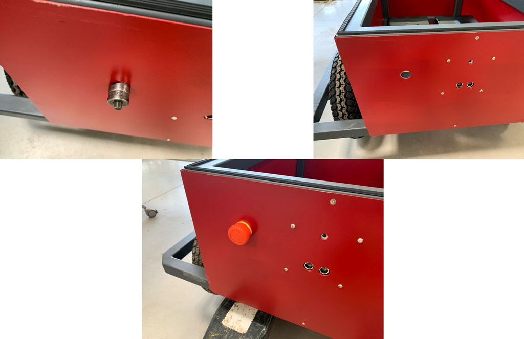
Security
For safety reasons I added an emergency stop button. My robot being powerful it is better to add a safety device in case of problem. For this I used a tool the exact size of my button. In case of emergency this button cuts immediately the current in the circuit.
Integration
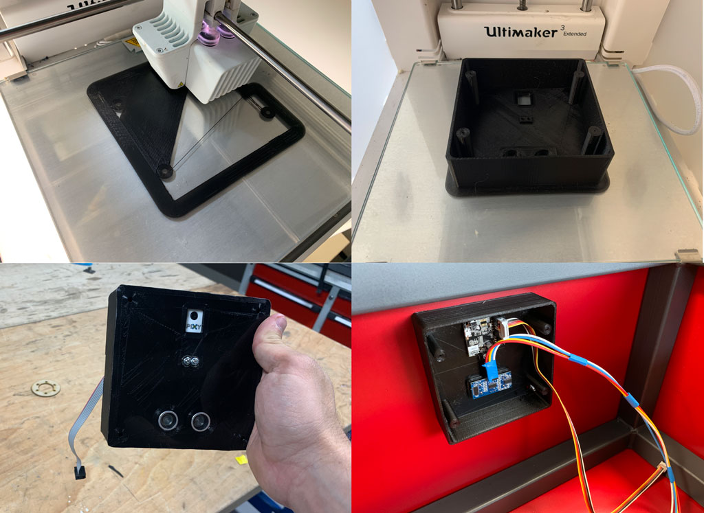
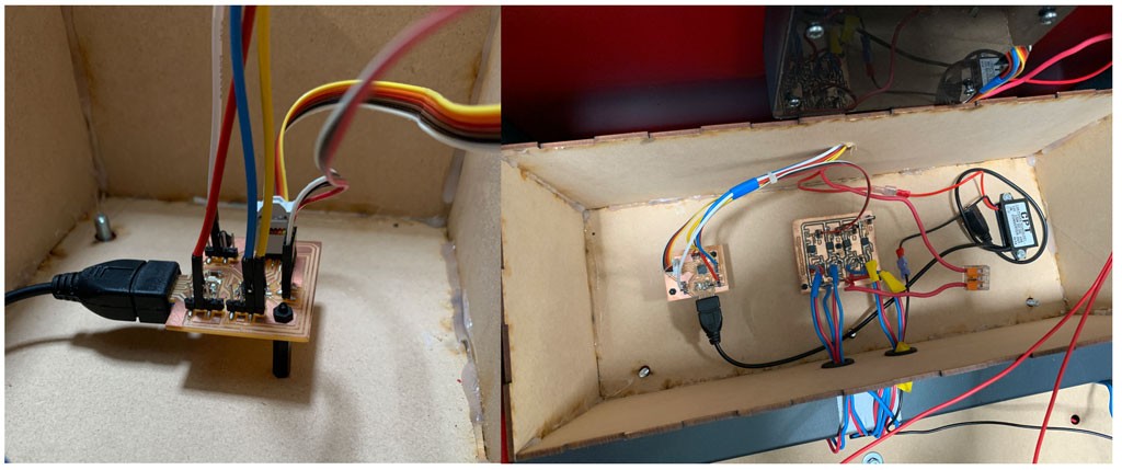
To hide all my wires and fix my different boards I decided to make some protective boxes.
To do this I 3D printed a box for my PixyCam and my ultrasound sensor. Wanting to play on the thickness of the materials I could only use this technology to make my fixing box. This allowed me to hide the screws of the PixyCam, just touch the ultrasonic sensor and make the fixation to close my box with screws.
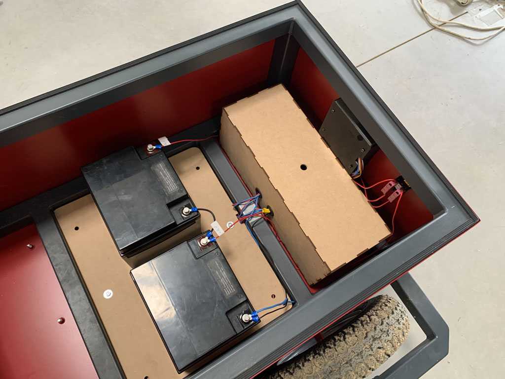
For the rest of the integration I used the laser cutter and 3mm MDF to make my protective box and my battery fixing. In my box is my motor control board, my SAMD21E and a 12V - 5V converter to power my SAMD21E. Moreover I took advantage of the screws of fixation of my motor cases to fix my batteries and to hide my wires of supply for my motors. For that I also used the laser cut and MDF of 3mm thickness.
At the beginning :
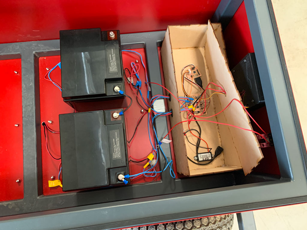
I used small screws to fix my boards firmly and used tape and zip ties to fix my wires together
At the end :
Hero video
Conclusion
I learned a lot during this training. Programming, electronic design, electronic components, 3D printing and scanning, managing a laser or a CNC were all things that were totally unknown to me at the beginning of the FabAcademy. This training is therefore a real asset to understand a little better the computerized world of today but especially of tomorrow. I also developed my English which is very important in a global context where negotiations are carried out in English. I still have many gaps in this language but this training has helped me enormously to progress.
Doing the fabAcademy was a great opportunity for me to learn new things and to finalise my agricultural engineering course. This training has played an important role in my education.
It was a real pride for me to put all my skills acquired during these weeks of courses into a single final project. In a single project there are electronics, programming, laser cutting, CAD, CNC, welding and so on.
Concerning my robot, I am aware that it is not perfect and would deserve some modifications.However, it works without too many errors. It deserved more power in the motors although it can move a load of 100kg as announced. This robot can be used as a basis for anyone who wants to build a robot.
Files
- Torque Excel table .xlsx
- Mechanical Drawing Motor.pdf
- Robot.f3z
- Wheels support drawing.pdf
- Robot body drawing.pdf
- Box PixyCam.stl
- Box PixyCam.f3d
- Files board SAMD21
- Files motor control board
- Code Robot.ino