8. Computer controlled machining
This week we had to build something big. Limited by time I settled for making a chair. My goal was to create a comfortable chair to limit regular back pain. Assignment
Do your lab’s safety training test runout, alignment, speeds, feeds, materials, and toolpaths for your machine
Individual assignment
Make (design+mill+assemble) something big (~meter-scale)
Hero shot

Fusion 360
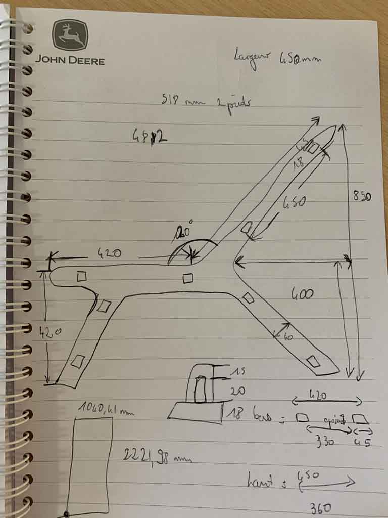
Before I started designing my chair I did some research on the internet to find the dimensions of the perfect chair. Thanks to this site (French site) I was able to find all the values to make the most comfortable chair possible. Then I made a quick little sketch on paper to get my head in order before I did it on Fusion360
Group assignment
Risk assessment check list
Before starting any work verify the next things:
- The building bed of the machine is clean and clear of any obstacle or object.
- The tools are in good mechanical state, it means there’s no sigh of rupture or crack in any mobile or spinning part of the machine.
- You are in company of a certified competent instructor and you have complete attention into the work.
- You are in a normal capable physical and mental condition, avoid working tired or after hours to prevent accidents.
- The CNC machine, is completely operative, and has had maintenance periodically.
- The spinning parts of the machine are well adjusted to their respective holders.
- There’s a well maintained electrical infrastructure for the power needed by the machine.
- You have visual and physical access to any emergency stop/cut-down button.
- You have verified that the minimum and maximum feed-rate and spinning speeds of the machine.
- The material you have selected its stable and with physical integrity so there’s no risk of any part projected as the material gets cut.
- You have ear, face and skin protection and your companion does have it too.
- You have visual contact with your companion, so there’s no risk of not receiving warning signals from you and viceversa.
- You’re wearing appropriate footwear.
Once you have started the CNC machine
- Verify that no person of object opposes obstacle to the building area and safety radius.
- Verify that the spindle mill and axis don’t get overloaded during the work by excessive:
- Spinning speeds.
- Feed-rate.
- Miss placed Z axis that compromises the sacrificial plate.
- Out of range X and Y axis motion.
- Don’t touch or try to clean the spindle while milling.
- Don’t try to remove any debris from the building bed while milling or with the spindle on.
- Be prepared to stop the machine if something seems to go wrong, it’s better to prevent any situation.
- If you notice a potential part of the machined material that can get projected, pause the process and stop the spindle, remove the part and then resume the process.
After work
- Ensure there are no debris or any large piece of material on the axis rails.
- Clean thoughtfully the building bed using the portable vacuum machine available in the “petit mechalab”.
- Check if the dust collector needs disposal of the collected dust.
- Check if the sacrificial plate it’s still in optimal condition.
- Protective wear is very important so once you’ve finished the work clean it and place it back on their corresponded stands or toolsets.
- Place the tools back in their toolsets or boxes identify those who belong in the “petit or gros” mechalabs.
- Dispose of the remaining materials and save some of it, if possible.
- For the disposal there’s a bucket outside the lab that will serve as combustible for “fire pits”
- For saving there’s an area close to the Okume and OSB racks.
- Please save only good quality materials.
Test
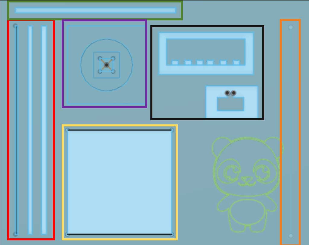
Red shape : test of the Y axis with several widths. All these tests were carried out with the 2D Contour tool. Our speed was set at 2,000 mm/min for a speed of 10,000 rpm and removed 5mm of material at each pass. Results: - The leftmost line was not cut as it was too small in width for the bit: 10mm for 10mm. - The middle line was well machined. After having measured the passage of the milling cutter we observed a difference of 0,1mm between the drawn widths and the reality. - The rightmost line was well machined. However, during the machining process we observed a lot of vibration, which led to large deviations in the measurements. In some places (in the middle of the line) there were deviations of up to 0.5mm. - The lines are well within the required length of 800mm Conclusion: the machine is accurate to the hundredth on its Y axis. In addition, be careful with the spacing between two parts, vibrations can occur and create an inaccuracy of the dimensions.
Green shape : X axis test. This test was carried out with the 2D Contour tool. Our speed was set at 3,000mm/min for a speed of 10,000rpm and removed 5mm of material at each pass. Results: - The line is the required length of 617mm - There was a difference in measurement of 0.1mm Conclusion: The machine is accurate to one hundredth on its X axis
Purple shape : Z axis test. All these tests were carried out with the 2D Pocket tool. Our speed was set at 2,000mm/min for a speed of 10,000 rpm and we removed 1mm on the first pass, 2mm on the next and 3mm on the last.
Result:
- Very accurate work from the machine we found no differences in dimensions.
Conclusion: This machine is very accurate on its Z axis.
Yellow shape : Test of the interior angles with the dogbones and precision of the cutting. This test was carried out with the 2D Contour tool. Our speed was set at 3,000mm/min for a speed of 10,000rpm and removed 5mm of material on each pass. Results: - The dogbones were well made and allowed for the insertion of a shape with a right angle - The dimensions are exactly respected. Conclusion : The dogbones plug-in can be useful for our project.
Orange shape : Test of the trace tool. Single pass at 1000mm/min and 10,000 rpm for the spindle. Working depth 18mm. Result: - Very precise work, we also observed a difference of 0.1mm in the middle of the part, probably due to a too high stress on the bit which caused a vibration. Conclusion: Interesting result but will not be used for our personal work. This technique requires a lot of time and creates important constraints for the tools.
Black shape :
This test was to find the value of press-fit. We did a test in cutting some holes at different values: 25.5 mm, 25.3 mm, 25.1 mm, 24.9 mm, 24.7 mm, 24.5 mm. We also did a shape to test these differents holes, a notch at 25 mm.
Result: - in the OSB wood, a 25 mm notch fir in a hole at 24.9 mm, so we don’t need clearance to do a press-fit. This test is working only for the kind of wood we cut, OSB. If we want to use another kind of wood, like okoume, we have to do again some test before milling the whole shape.
General conclusion :
Our professional machine is accurate on all these axes. Slight inaccuracies on the X and Y axes were found due to high stresses which led to vibrations. For our own work we can use the speed values of 3,000 mm/min for the feedspeed, 10,000 rpm for the spindle and 5mm thickness for the multiple depth.
Milling
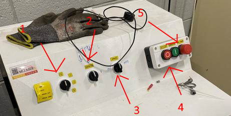
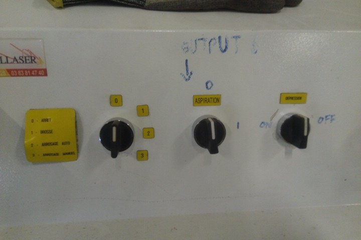
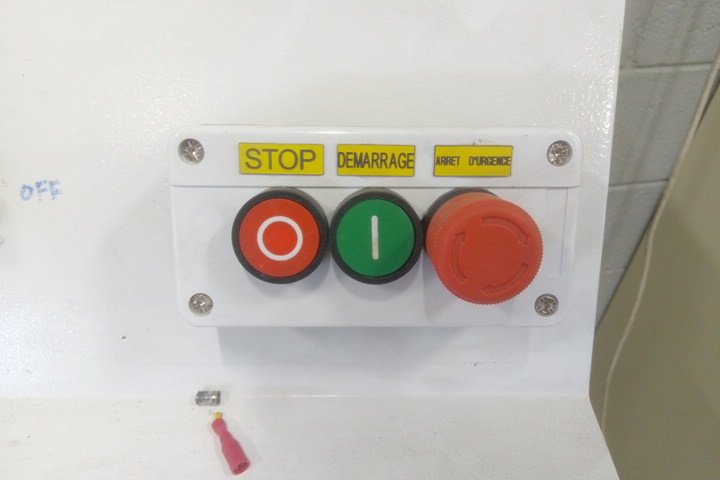
The machine works with command center with the button that up or down the skirt (1), the suction of the table (2) and the dust collector (3) switch on off buttons. There is the stop button use to trun off the device (4) and an emergency stop (5).
First, switch on the machine by pushing the green button. Let the machine do the home process.
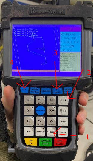
On the device remote. First we have to select output 6 so that the skirt goes down for the vaccuum of the dust. The output 6 has to be turned in red in the input / output menu. Then go back to the menu. Mode change the mode of moving.
The tool switch button in blue is to change the tool on the rack, and select the tool (3).
Then do the X and Y manually. Push on XY -> 0 (2).
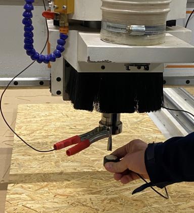
Then there is the toolset button to do the z at 0 automatically (1). We need to plug the probe height of cnc (in metal) to the device and the pliers to something connected to the milling bit. And then push the button. The Z has to be done with depressure.
To laucnh a file from the USB, click on file (4).
To do the Z, first we test the conductivity by holding the probe height in the air, to test that the device is seeing right the detector and won’t plung through the material.
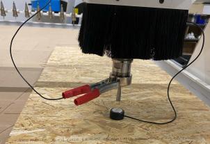
Then we can do the Z on the wood with the suction depresure.
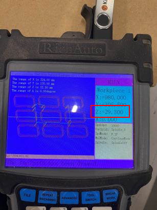
Here is the value, Z = 29.3 mm shown on the remote when the milling bit has touch the probe height.
So the correct tool has to be selected, then launch the file from the USB Key, check the output 6.
Apply the dust extractor, switch on the depressure and put on the skirt (on 1 on the command center) but we can lift it up to see.
Individual assignement
Design
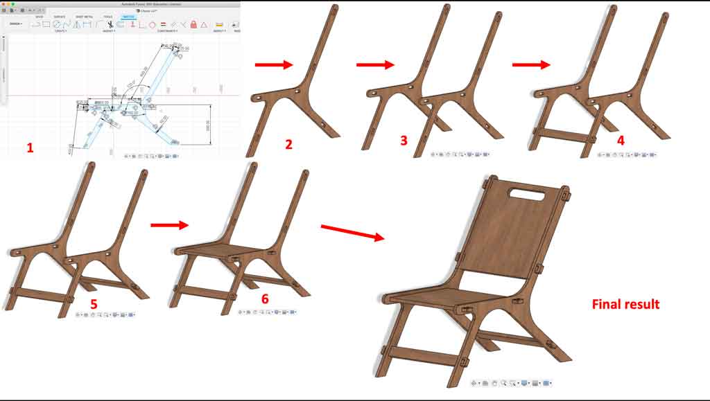
As is often the case, you have to start by making a plan. Having used Fusion360 several times in the past week I naturally used this software to make my 3D model.
1 : The sketch of my chair. Everything is constrained by values.
2 : I then extruded the sketch with my parametric value
3 : I copy-pasted the body then moved it
4 : I made a support bar then moved it on the plane so that it fits in the holes
5 : I copy-pasted the front bar then moved it
6 : I made the seat then extruded the thickness of the board
7 : I made the backrest and then extruded the thickness of the board. Here is the final result
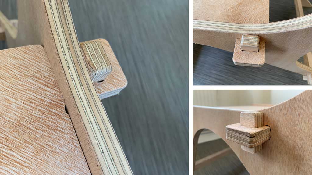
Why use this kind of joint?
I decided to use mortise and tenon joints locked with a pin for several reasons :
- Easy to dismantle
- Easy to make
- Very strong
- Already used in the past to make a workshop bench
- I find this type of joint very beautiful despite the fact that it is not discrete
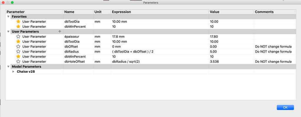
Parametric values
When I started to make my plan I didn’t know exactly the wood I was going to use and therefore I didn’t know its thickness. For this I used a parametric value which I called “épaisseur” (thickness in French). All my shapes for which there was an assembly or where the thickness played a role I placed this value. The advantage of using parametric values is that when I measured the exact value of my material I changed it in my table. By validating this action all my values which had as denomination “épaisseur” changed automatically and quickly.
Once my 3D modelling was finished I had to put all my bodies on the same plane for CNC machining. To do this I used the “move” function and manually moved my parts so that they were on the same plane.
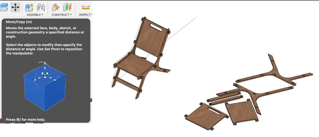
Once I have put all my parts on the same plane and in an optimal way I made my tenons which will be used to maintain my elements that I fit together
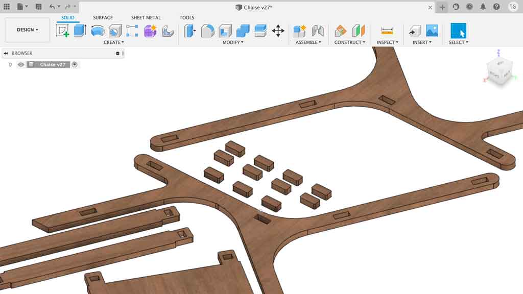
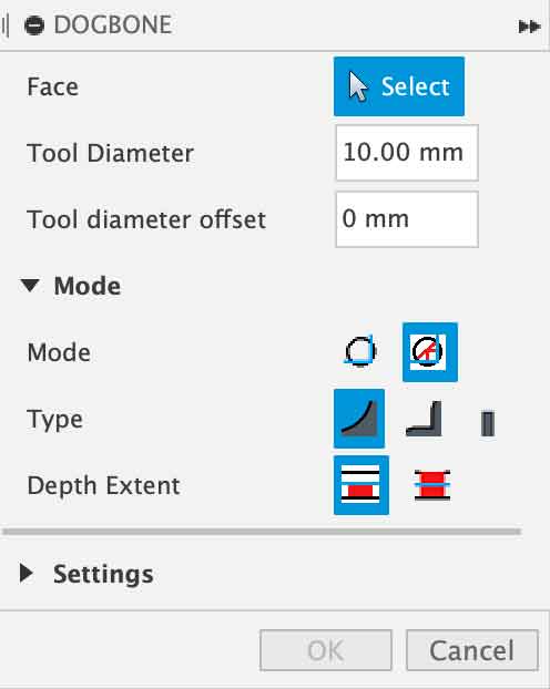
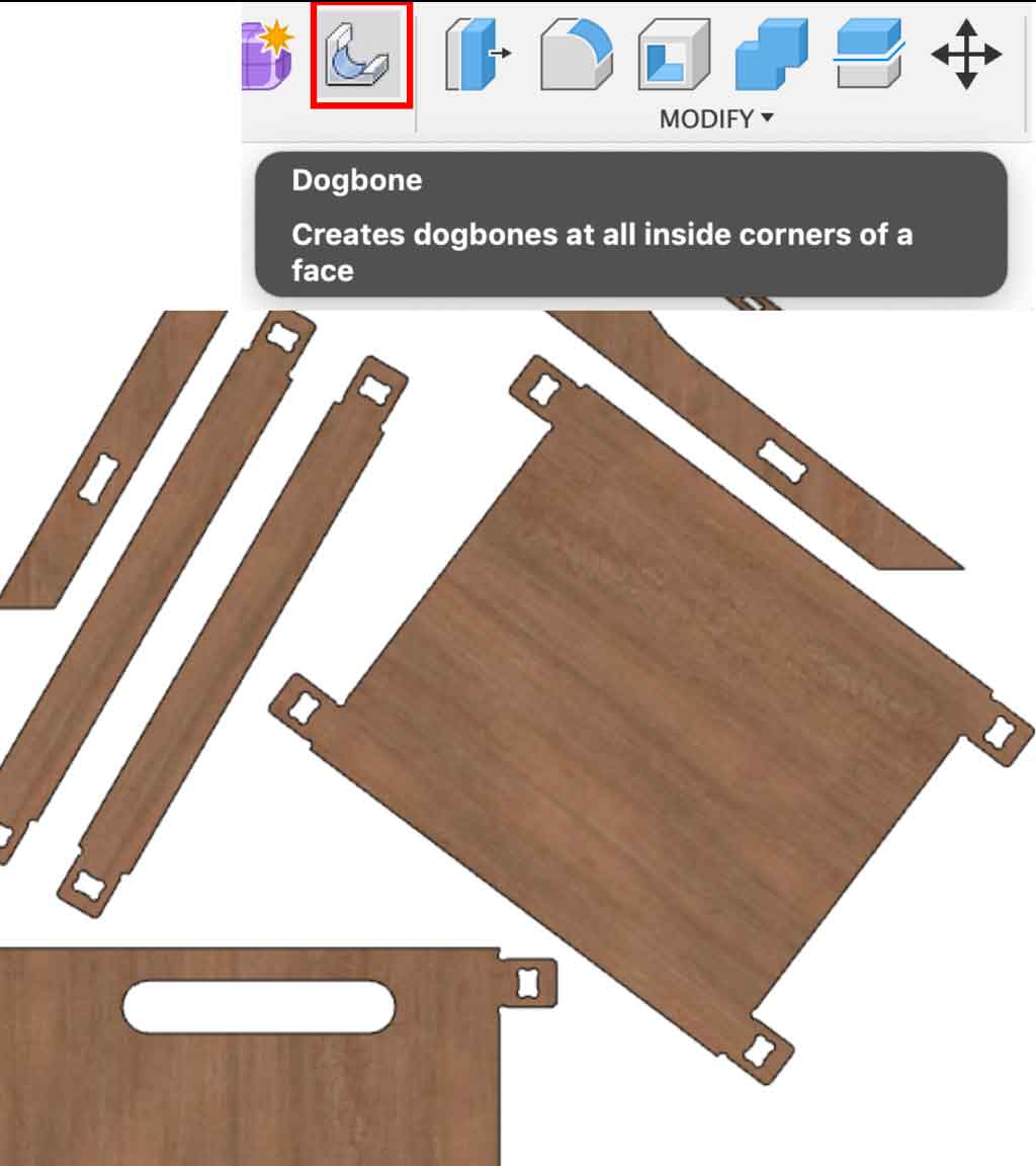
The dogbones
Before leaving the design part, the last step has to be done. The dogbones make it possible to fit the elements together correctly. As the drill bit is round, it cannot make an internal angle to the square. To do this, you have to make the corners bigger and rounder to allow the other piece to fit perfectly into the other. To do this I used a plug-in and followed the installation instructions. Once in Fusion360 it is quicker and more accurate to make these dogbones with just a few clicks.
- Select the “dogbones” tool
- Select your faces
- Edit your tool diameter
- Select your mode
- Set up your tool and confirm.
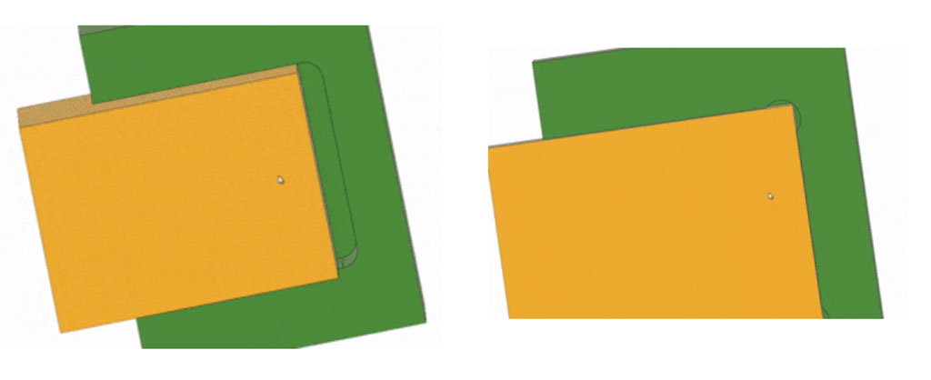
Some illustrations of the use or not of dogbones
 Credit : Blog.brics
In this case it is easy to see that without the use of dogbones the piece does not fit properly into the other piece.
Manufacture
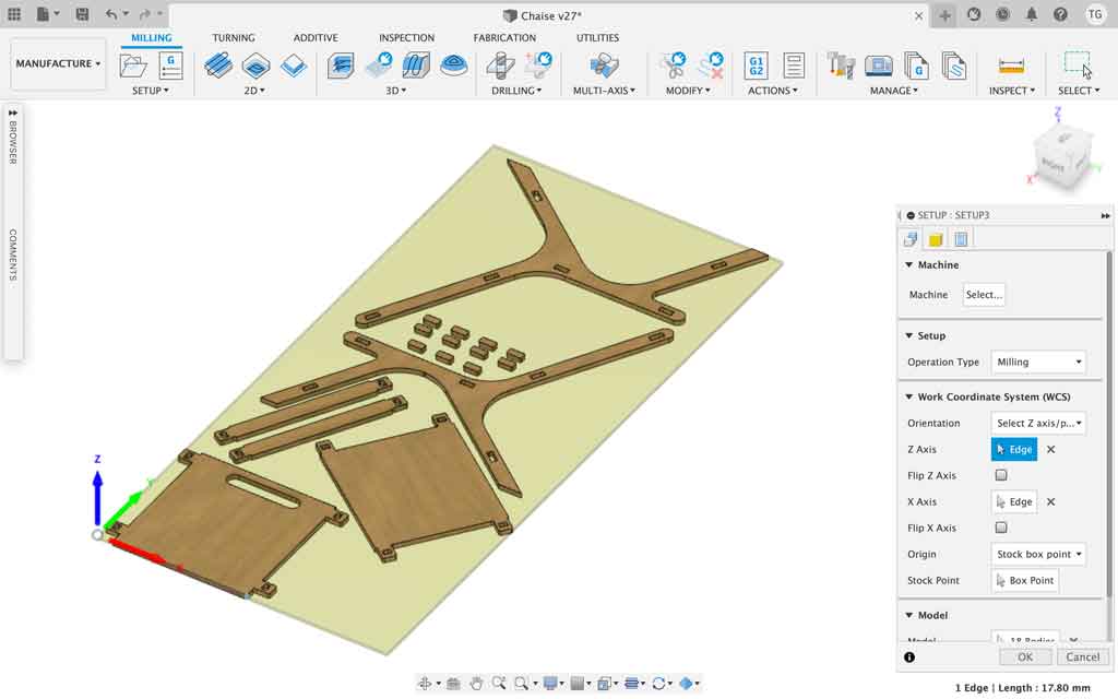
When you have made and finished your design you need to generate the code that will be sent and read by the machine. To do this, follow these steps
- Do the setup
- Edit your operation type
- Edit the orientation of your materiel. To do this, select the sides that are placed on the X-axis and select the sides placed on the Z-axis.
- Position your point of origin. It is preferable to place the point of origin on a top corner of your material
- Select the bodys you wish to mill
- Check in the “stock” tab that all your parts fit on the board
- Validate the setup.
- Editing a contour
- Select 2D-Contour
- Choose the bit you are going to use (you may have to set it up, I will explain how to set up a tool on Fusion later)
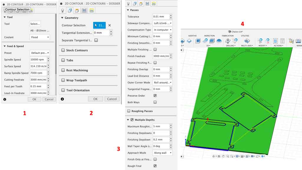
- Check the feed and speed settings (normally if you have done the tool settings correctly all these values are automatically linked to the tool used) (1)
- Go to the geometry tab and select your contour. It is preferable to use the bottom contour so that the machine will cut correctly.
- You can edit other parameters if you wish, such as Tabs if your part is small and there is a risk of projection. I used tabs only for the tenons. (2)
- Go to the Passes tab and select the multiple deth option. This allows you to make several milling passes to cut the part. This allows you to preserve the tools by removing very little material. I decided to remove 5mm of material with each pass of the bit. The Stock to leave option can be used if you have a lot of material to remove. The machine will first do the bulk of the work very roughly and quickly and then finish with more precision. This saves time if there is a lot of material to machine. (3)
- Validate your operation once you have checked all these points.
- Your stock will turn green and you will see the path of the cutter. (4)
What are Tabs?
Tabs are small ties that hold objects in place once they are cut. The machine will leave very little material which will allow the user to easily detach these small elements and also prevent the part from moving.
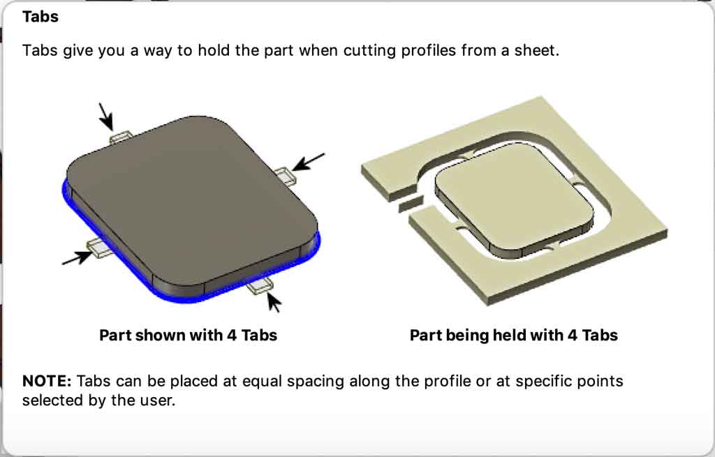
For my part I used Tabs for my tenons (small piece that I use to lock my objects together) because these pieces were really small and very dangerous when cutting. These pieces were likely to fly and collide with someone, by using tabs I limited the risk of accidents
- Visualisation and simulation tools
- Fusion360 has a simulation tool that allows you to see the milling process in accelerated mode. This allows you to quickly see if you have made any mistakes in the settings. This tool is very useful to check our settings.
- In this tool you can also see the time needed to cut.
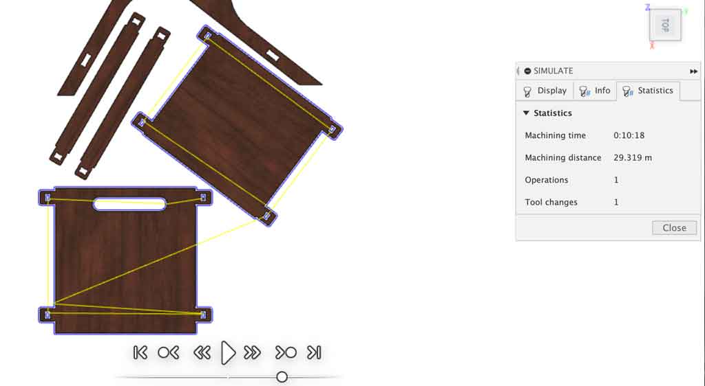
It is important to look at the cutting order of the machine when viewing. It is best to start with the inside cuts. If the machine starts with the outer cut, there is a risk that your part will move. If your part moves then your next cuts will not be placed where you want them.
Why should we care about cutting time?
At AgriLab we have only one CNC, so we have to share it. We were told to use the machine for a maximum of 4 hours. That’s why I looked a lot at the cutting time. However, we found that the simulation time was not the actual time spent machining the part. The software should not take into account the time spent plunging into the material
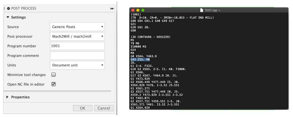
- Generation of the post-production code
- In order for the machine to machine your object, it must generate a code that it can read. At AgriLab our machine reads .nc.
- Go to the post-process tab
- Select your machine, we have a Mach2Mill
- Generate your code
- We have a small problem on our machine, we need to delete a command line so that it can do the job correctly.
G43 Z15. H8
- Save your file as .nc and send it to your machine.
If we don’t remove this line our machine cuts in the air…
How do I set up a tool on Fusion360?
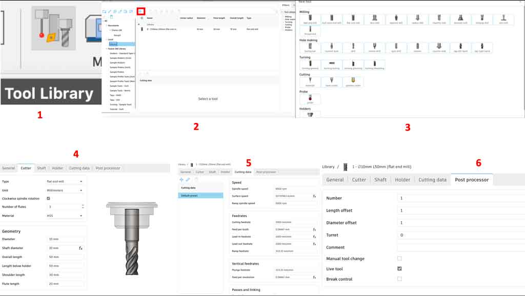
- In the manufacture page, there is a tool library icon. (1)
- Open this icon and go to the Local library tab to register a tool.
- Click on the little “+” at the top (2)
- Select your bit type, for my part I used a flat end mill (3)
- Fill in the data for your bit in the cutter tab (4)
- Fill in the cutting parameters for this bit in the cutting data tab (5)
- If your machine is equipped with a live tool like ours, enter its position on the live tool in the post process tab (6)
- Validate your settings
You can now select your tool in the cutting operations.
All these values used to set up my tool were measured during the group assignment. During the test period we used this bit, which we think is optimal for our future cuts. We mounted it on a milling head. Once mounted on the head we were able to take the measurements.
Why did you use a 10mm drill bit and remove 5mm of thickness at each pass?
As mentioned earlier we decided during the group tests to use a 10mm bit for one main reason:
Having a tool with a large diameter makes it more rigid so we can make deeper cuts and faster. Time is really our enemy at AgriLab, so we need to find ways to make it possible to mill quickly. In general we were advised to use a 6mm drill bit but if you increase the diameter of a tool by 2 then its rigidity increases by 16, so you can go faster and mill deeper. During this group test we tried several speeds and several cutting thicknesses. That’s why I decided to use 3,000mm/min in cutting speed for a cutting depth of 5mm. All these values are the result of the group test.
The most important parameters to remember:
- Spindle speed : 10 000 rpm
- Cutting feedrate : 3 000mm/min
- Plunge feedrate : 333 mm/min
- Maximum roughing stepdown : 5mm
- Tolérance : 0,1mm
All these parameters are for 18mm wood with a 10mm drill bit. These parameters would not be appropriate for other materials such as iron and wood harder than okoume. They have been tested in our group tests and approved by our local instructors
Exporting files
For my part I decided to make several files. The main reason is that if the machine makes an error at the end I don’t have to start over. I only start again the file on which an error was made. This reduces the risk of wasting time. So I exported a file for the seat, a file for the legs, a file for the support bars and a file for the tenons
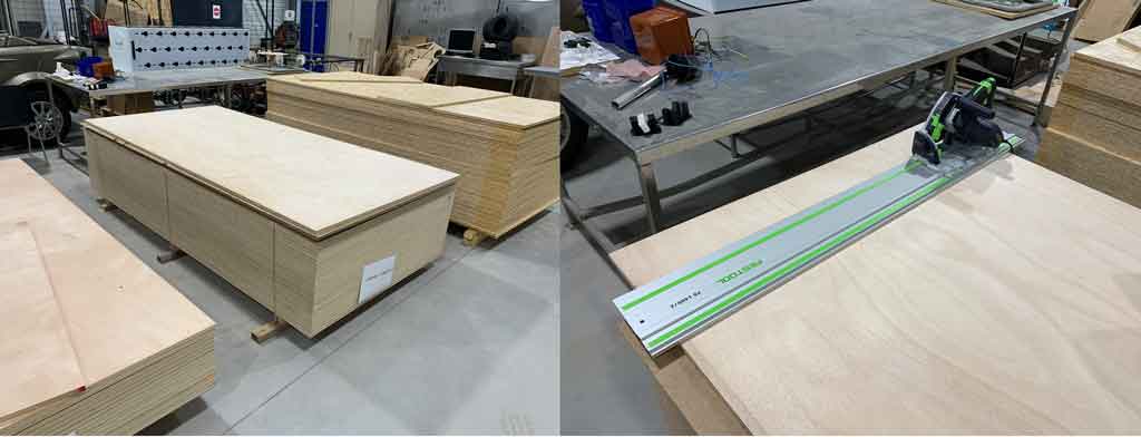
Preparing my materiel
Our wooden boards are 250cm x 120cm and the machine has a cutting table of 240cm x 150cm. So I had to cut 10cm off the length of my board to fit into the machine. I used a circular plunge saw to cut the 10cm off-cut.
Why okoumé?
I decided to use okoume for aesthetic reasons. I had the choice of using OSB but I find it less suitable for making furniture. Also OSB is more likely to contain splinters which can be uncomfortable if you sit on it.
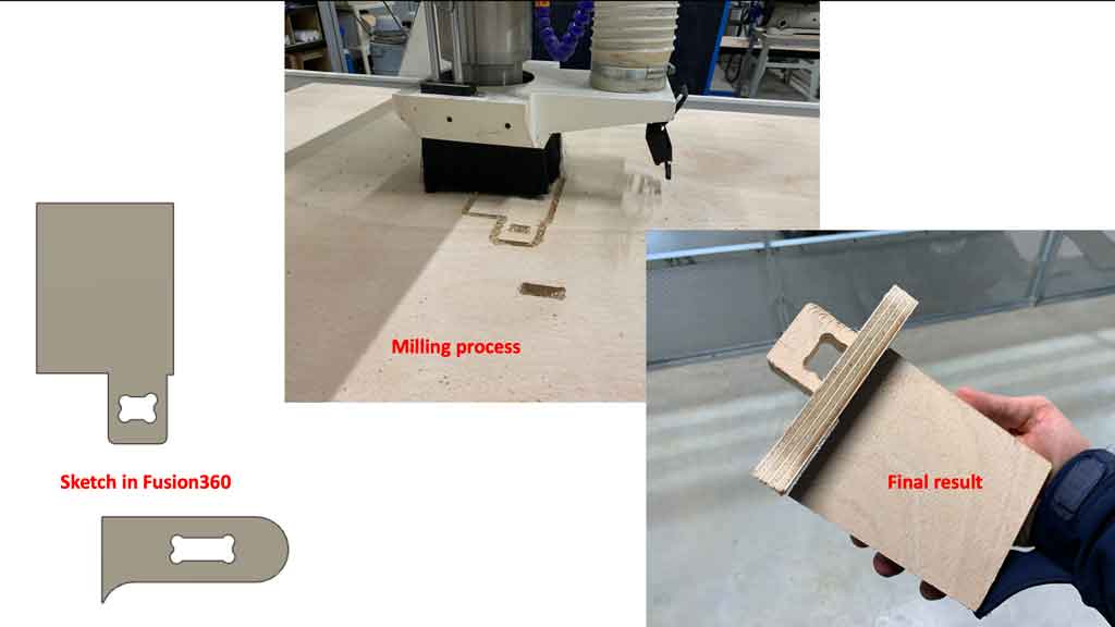
Test before machining
Before machining my entire project I preferred to mill a part of my project to check if all my parts fit together correctly. To do this I created a sketch of an assembly and machined this part. This test allowed me to see that I had to put more clearance. So I added 0,2mm of clearance on top of the original thickness to make the objects fit together perfectly.
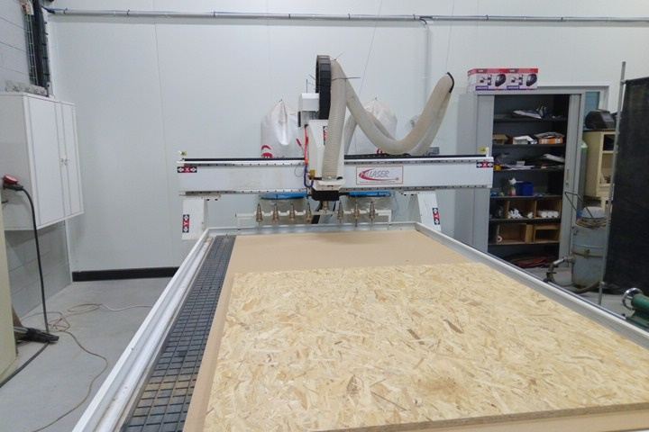
Machine descriptions
At AgriLab we have a large 3-axis CNC with a cylinder turner on the side. This machine is equipped with a vacuum table which allows to clamp the material and to prevent it from moving.
The size of the vacuum table is 250cm x 150cm x thickness depending on other parameters (martyre, length of the milling cutter,…)
We also have a tool change system with 8 storage compartments.
Oil bath circuit for metal machining
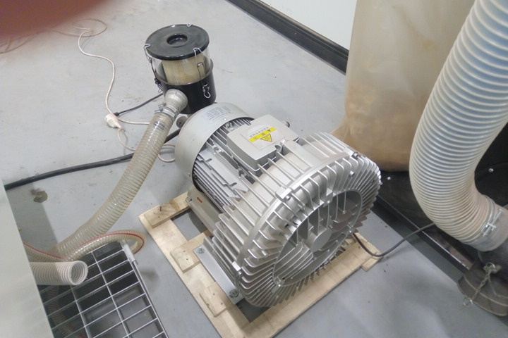
Wood chip extractor.
The device is composed of several elements
 The control unit
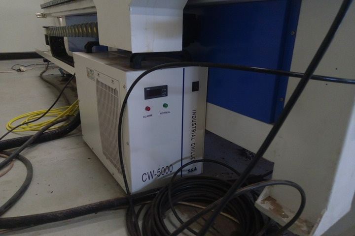 A cooler for a spindel motor
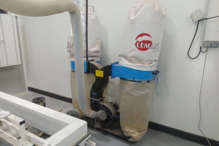 The vacuum dust
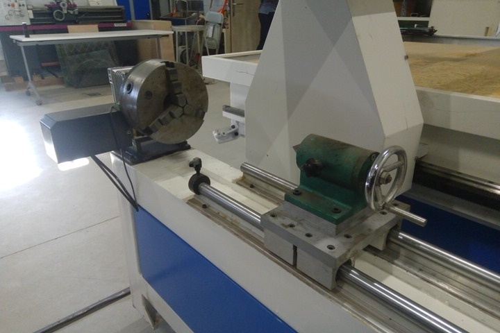 The cylinder turner on the side
 The vacuum for the table
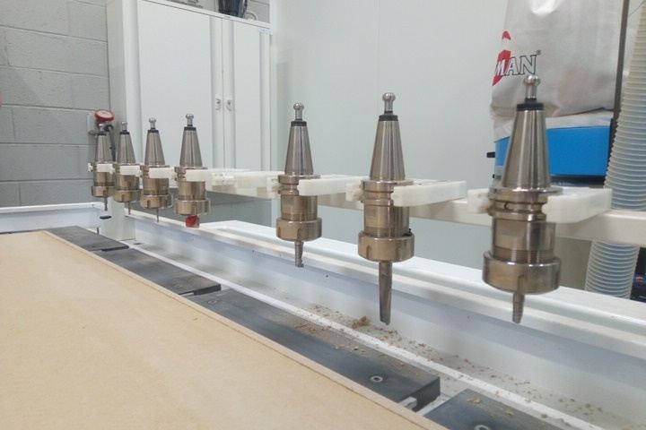 The tool changer
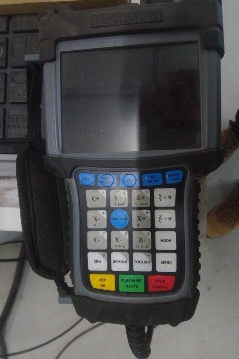
The remote
The remote control is used for several things:
-
Control the position of the cutter, click on the X, Y or Z arrow to make a movement. The + or - keys reverse the direction of movement. The fast/slow key (located in the centre and blue) changes the speed of the movement by increasing the precision of the movement.
-
Realize the original coordinates. The XY->0 is used to set the origin point in X and Y. The ZC->0 is used to make the origin point in Z. The toolset button is an automatic Z, you must use an electrical sensor that measures the contact between the spindle and the sensor. This is an accurate way to determine the Z.
-
You can change a tool that is in the tool changer with the tool switch button
-
You can select your file located on the usb stick. You confirm with the yellow OK button. And you start the work by clicking on the green run/pause button.
Machining
Once the merge file is exported and renamed .nc and the line deleted I can put my file on the machine’s USB stick. To avoid any risk of error I decided to create several files and send them one by one. This allows me to avoid starting over if my last step fails, I would have to start over only the faulty file. I then started with the longest parts to machine and finished with the tenons. Here is an illustration of the machining process
Assembly and result
Once the machining was done I assembled all my pieces together. They all fit well but I had to help them fit with a hammer and a wooden wedge to avoid damaging my chair. Here is the result once assembled
Conclusion
I was very pleased to have made something big. To discover, to learn, to see this kind of machine is not common and I am very happy to do this formation to have this chance to handle professional machines normally reserved for the industry. I am quite satisfied with the result of my chair, I find it aesthetically beautiful but a bit fragile on some points… I would have to consolidate it a bit more. The precision of the machine really impresses me a lot because my pieces, although very large, fit perfectly together. This week has really good and I would like to thank the AgriLab team for their patience in teaching us how to use the machines.
Bonus
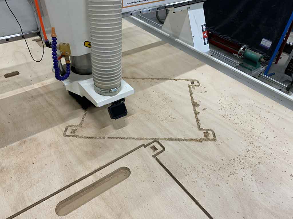
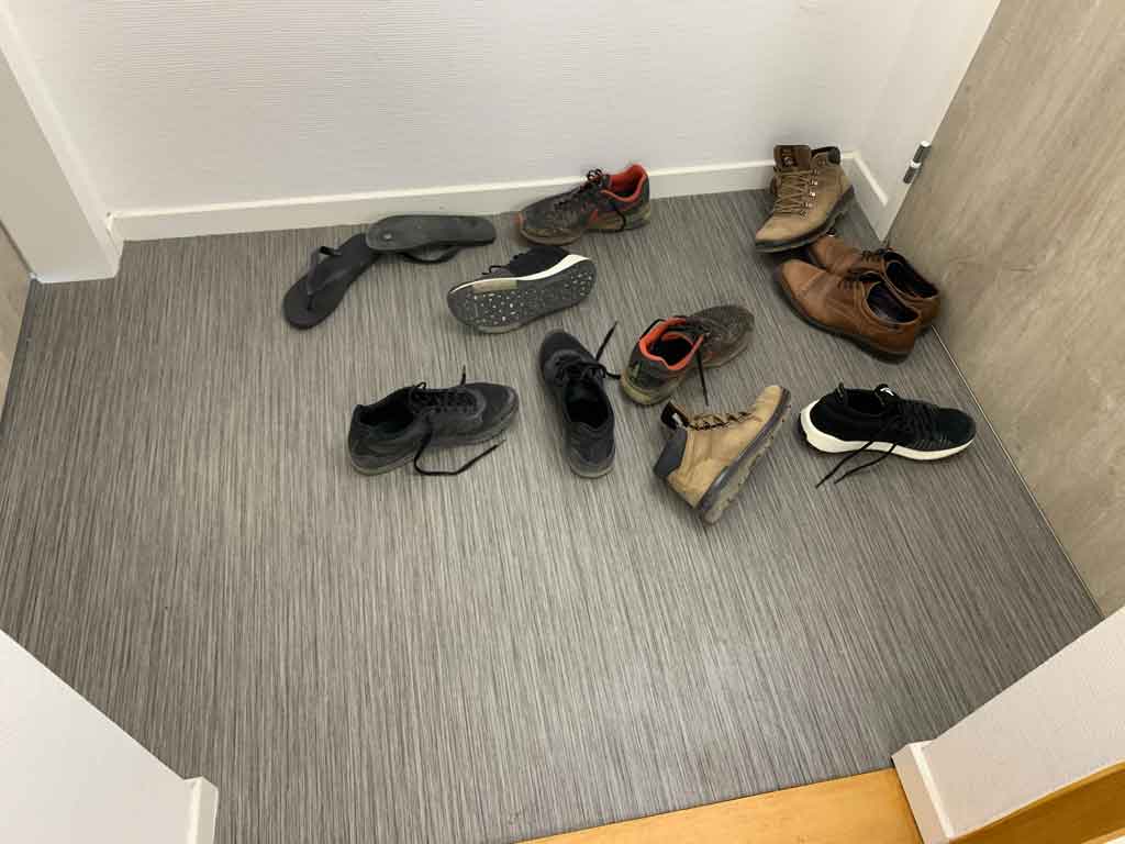
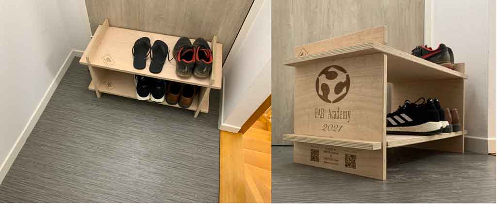
During week 9 (embedded programming) with my roommate Antonio we decided to make a small piece of furniture to store our shoes. We’ve been trying to organize the entrance of our flat for a while now, but as the picture shows, we can’t really do it…
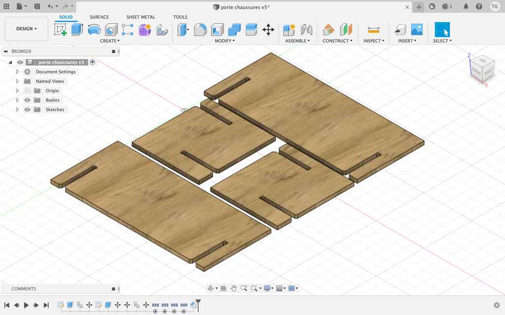
Having a little time and some wood scraps we decided to create this little piece of furniture. We made the plans on Fusion360 and generated the G-code for our CNC machine.
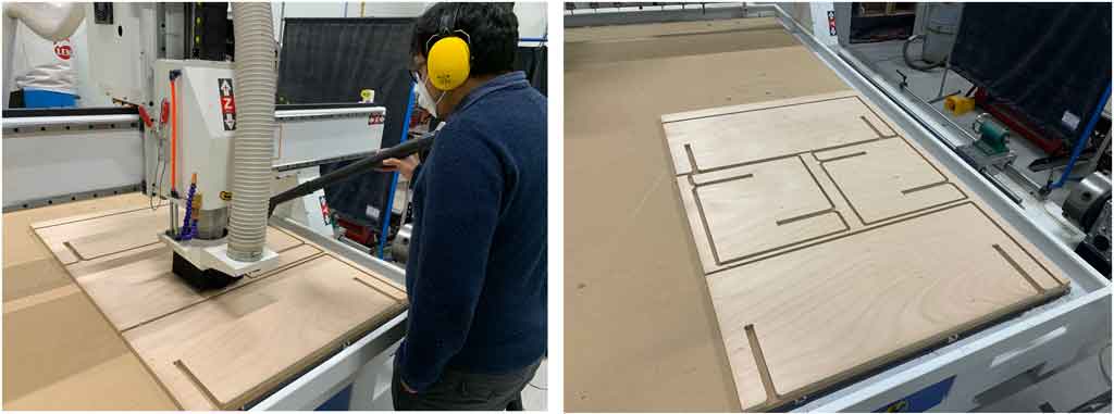
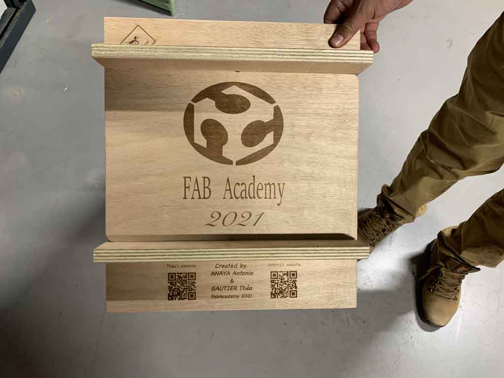
After machining our parts we had the idea to use the laser cutter to engrave some of the tops. This piece of furniture will stay in the AgriLab flat for the next FabAcademy students so we decided to mark our work. For this we engraved our names and our QR codes from our respective sites. Finally we added the FabAcademy logo and the year we made it.
Last step, the assembly! The pieces fit perfectly into each other which made the work easier. Here is the final result, it’s much better like this ;)