9. Embedded programming
This week was dedicated to programming and understanding microcontrollers. By reading the SAMD11C datasheet I was able to understand a little bit better how this part works. Finally I used several IDE platforms to write the code and send it to my board made in week 7
• Group assignment :
Compare the performance and development workflows for different microcontroller families.
Document your work (in a group or individually).
• Individual assignment :
Read the datasheet for the microcontroller you are programming.
Program the board you have made to do something, with as many different programming languages and programming environments as possible.
The SAMD11C in a few words
The Atmel SAMD11C is part of the new generation of microcontrollers.
“A low-power, high-performance ARM® Cortex®-M0+ based flash microcontroller, the Microchip’s ATSAMD11C14 is ideal for a wide range of home automation, consumer, metering and industrial applications.” Atmel
After reading the datasheet here is the essential information to remember about this small electronic component.
All this information is taken from the datasheet but I made the summary table with the comments.
| Configuration Summary | SAMD11C-14 pin SOIC | More informations |
|---|---|---|
| Number of pins | 14 | |
| Number of I/O pins | 12 | |
| Flash memory | 16 KB | The High-Speed bus is implemented as a bus matrix. All High-Speed bus addresses are fixed, and they are never remapped in any way, even during boot. |
| SRAM | 4 KB | |
| Time counter (TC) | 2 | The TC consists of a counter, a prescaler, compare/capture channels and control logic. The counter can be set to count events, or it can be configured to count clock pulses. The counter, together with the compare/capture channels, can be configured to timestamp input events, allowing capture of frequency and pulse width. It can also perform waveform generation, such as frequency generation and pulse-width modulation (PWM). |
| Output channels for TC | 2 | |
| Timer Counter for Control (TCC) | 1 | The Timer/Counter for Control applications (TCC) consists of a counter, a prescaler, compare/capture channels and control logic. The counter can be set to count events or clock pulses. The counter together with the compare/capture channels can be configured to time stamp input events, allowing capture of frequency and pulse-width. It can also perform waveform generation such as frequency generation and pulse-width modulation. Waveform extensions are intended for motor control, ballast, LED, H-bridge, power converters, and other types of power control applications. It enables low- and high-side output with optional dead-time insertion. It can also generate a synchronized bit pattern across the waveform output pins. The fault options enable fault protection for safe and deterministic handling, disabling and/or shut down of external drivers. |
| Output channels per TCC | 8 | |
| Direct memory access channels | 6 | The Direct Memory Access Controller (DMAC) contains both a Direct Memory Access engine and a Cyclic Redundancy Check (CRC) engine. The DMAC can transfer data between memories and peripherals, and thus off- load these tasks from the CPU. It enables high data transfer rates with minimum CPU intervention, and frees up CPU time. With access to all peripherals, the DMAC can handle automatic transfer of data between communication modules. |
| USB interface | Yes | |
| Serial Communication Interface (SERCOM) | 2 | The serial communication interface (SERCOM) can be configured to support a number of modes; I2C, SPI, and USART. Once configured and enabled, all SERCOM resources are dedicated to the selected mode. The SERCOM serial engine consists of a transmitter and receiver, baud-rate generator and address matching functionality. It can be configured to use the internal generic clock or an external clock, making operation in all sleep modes possible. |
| Analog-to-Digital Converter (ADC) channels | 5 | The Analog-to-Digital Converter (ADC) converts analog signals to digital values. The ADC has 12-bit resolution, and is capable of converting up to 350ksps. The input selection is flexible, and both differential and single-ended measurements can be performed. An optional gain stage is available to increase the dynamic range. In addition, several internal signal inputs are available. The ADC can provide both signed and unsigned results. ADC measurements can be started by either application software or an incoming event from another peripheral in the device. ADC measurements can be started with predictable timing, and without software intervention. Both internal and external reference voltages can be used. |
| Analog Comparators (AC) | 2 | The Analog Comparator (AC) supports two individual comparators. Each comparator (COMP) compares the voltage levels on two inputs, and provides a digital output based on this comparison. Each comparator may be configured to generate interrupt requests and/or peripheral events upon several different combinations of input change. Hysteresis and propagation delay are two important properties of the comparators; dynamic behavior. Both parameters may be adjusted to achieve the optimal operation for each application. The input selection includes four shared analog port pins and several internal signals. Each comparator output state can also be output on a pin for use by external devices. |
| Digital-to-Analog Converter (DAC) channels | 1 | The Digital-to-Analog Converter (DAC) converts a digital value to a voltage. The DAC has one channel with 10-bit resolution, and it is capable of converting up to 350,000 samples per second (350ksps). |
| Real-Time Counter (RTC) | Yes | The Real-Time Counter (RTC) is a 32-bit counter with a 10-bit programmable prescaler that typically runs continuously to keep track of time. The RTC can wake up the device from sleep modes using the alarm/compare wake up, periodic wake up or overflow wake up mechanisms. |
| RTC Alarms | 1 | |
| RTC compare values | 1 32-bit value or 2 16-bit values | |
| External Interrut Lines | 8 | The External Interrupt Controller (EIC) allows external pins to be configured as interrupt lines. Each interrupt line can be individually masked and can generate an interrupt on rising, falling or both edges, or on high or low levels. Each external pin has a configurable filter to remove spikes. Each external pin can also be configured to be asynchronous in order to wake up the device from sleep modes where all clocks have been disabled. External pins can also generate an event. |
| Peripheral Touch Controller (PTC) channels for mutual capacitance | 12 (4x3) | |
| Peripheral Touch Controller (PTC) channels for self capacitance | 7 | |
| Maximum CPU frequency | 48MHz | |
| Packages | SOIC | |
| Oscillators | 32.768kHz crystal oscillator (XOSC32K) 0.4-32MHz crystal oscillator (XOSC) 32.768kHzinternal oscillator (OSC32K)32kHz ultra-low-power internal oscillator (OSCULP32K) 8MHz high-accuracy internal oscillator (OSC8M) 48MHz Digital Frequency Locked Loop (DFLL48M) 96MHz Fractional Digital Phased Locked Loop (FDPLL96M) | |
| Event System channels | 6 | The Event System (EVSYS) allows autonomous, low-latency and configurable communication between peripherals. |
| SW Debug Interface | Yes | |
| Watchdog Timer (WDT) | Yes | The Watchdog Timer (WDT) is a system function for monitoring correct program operation. It makes it possible to recover from error situations such as runaway or deadlocked code. The WDT is configured to a predefined time-out period, and is constantly running when enabled. If the WDT is not cleared within the time-out period, it will issue a system reset. An early-warning interrupt is available to indicate an upcoming watchdog time-out condition. |
| Temperature range | -40 to 85°C | |
| Operating voltage | 1,62 to 3,63 V | |
| Processor | ARM Cortex-M0+ CPU running at up to 48MHz |
Schematic of the SAMD 11 C with pin assignment. You can also see the white dot on the top left of the component which is useful to quickly identify the direction when soldering.
 Picture of the different pins of the SAMD11C (source datasheet)
Here is a more general diagram of the functioning of the SAMD11C. This representation allows us to begin to understand the operation of the microcontroller.

Micro:bit
During the bootcamp we had a workshop on a very simple computer language, the blocks from micro:bit. This is very intuitive for beginners and very easy to understand. Thanks to this training we built a small car with my colleague Elina. We asked it to do very simple things, like driving in a straight line, turning on LEDs or stopping when the B button was pressed. This allowed us to see the logic of coding which was very useful this week to make some c or c++

Python language
On micro:bit you can also see the correspondence with the python language. Once I finished my program with the blocks I switched to see the code in python. Here is the correspondence of my blocks in python language.

Here is the corresponding code in Python
def on_button_pressed_a():
    basic.show_string("Go !")
    servos.P2.run(90)
    servos.P1.run(-90)
input.on_button_pressed(Button.A, on_button_pressed_a)

def on_button_pressed_ab():
    basic.show_leds("""
        . . # . .
        . . # . .
        # . # . #
        . # # # .
        . . # . .
        """)
    servos.P2.run(90)
    servos.P1.run(-90)
input.on_button_pressed(Button.AB, on_button_pressed_ab)

def on_button_pressed_b():
    kitronik_servo_lite.stop()
    basic.show_string("STOP")
    basic.show_leds("""
        # # # # #
        # # # # #
        # # # # #
        # # # # #
        # # # # #
        """)
input.on_button_pressed(Button.B, on_button_pressed_b)

bluetooth.start_button_service()

def on_forever():
    pass
basic.forever(on_forever)
Here is a short video of the functionality of our car
Programming my board
Before starting to program my board to do a few things, it needs to be flashed. I already did this step during week 7 but I’ll explain it again quickly above.
My colleague Elina then helped me to flash my board. On my computer I couldn’t get my board to flash, she kindly offered to try it on her computer, it worked.
We plugged the programmer and my board together and she wrote this sentence in her terminal :
edbg -b -t samd11 -pv -f sam_ba_Generic_D11C14A_SAMD11C14A.bin


After Elina helped me to flash my board with the bootloader I used the Arduino application to flash my LED. Now that my board has the bootloader I don’t need the cables anymore, I can directly connect to the USB port.
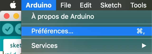
First of all I need to download a pack so that the Arduino application can communicate with our SAMD11C microprocessor. To do this, open the Arduino application and go to Arduino > Preferences then paste this link into this location:
https://www.mattairtech.com/software/arduino/beta/package_MattairTech_index.json

Once you have registered this new link you should also download the boards. To do this you need to open the tools tab > board manager. Type Mattairtech in the search bar and download the pack


When you are ready you can connect your board to your computer via a USB port. Go back to Tools and select your board. You also need to select your USB communication port. Be careful I’m on a Mac, I know it’s different on Windows or Linus


When you have selected everything you can send your code to your board. For my par I used the default code in arduino to generate my blinking. The only change I added is that I changed the pin out number to match my board. In order to know which number I used for this schema. My LED is connected to pin 2 and my button is connected to pin 5.
void setup() {
  pinMode(2, OUTPUT);
}

void loop() {
  digitalWrite(2, HIGH);
  delay(500);
  digitalWrite(2, LOW);
  delay(500);

}

Small reminder of my board
My LED is connected to pin 2 and my button is connected to pin 5.

Pull-up resistor
Pull-up resistors are very common when using microcontrollers (MCUs) or any digital logic device. Let’s say you have an MCU with one pin configured as an input. If there is nothing connected to the pin and your program reads the state of the pin, will it be high (pulled to VCC) or low (pulled to ground)? It is difficult to tell. This phenomena is referred to as floating. To prevent this unknown state, a pull-up or pull-down resistor will ensure that the pin is in either a high or low state, while also using a low amount of current.

With a pull-up resistor, the input pin will read a high state when the button is not pressed. In other words, a small amount of current is flowing between VCC and the input pin (not to ground), thus the input pin reads close to VCC. When the button is pressed, it connects the input pin directly to ground. The current flows through the resistor to ground, thus the input pin reads a low state. Keep in mind, if the resistor wasn’t there, your button would connect VCC to ground, which is very bad and is also known as a short.
Since pull-up resistors are so commonly needed, many MCUs, like the SAMD11C, have internal pull-ups that can be enabled and disabled. To enable internal pull-ups on an Arduino IDE, you can use the following line of code in your setup() function:
pinMode(5, INPUT_PULLUP);
Programming ESP32
During the Interface and application programming week I also programmed an ESP32. This microcontroller is different from the others already mentioned. Here are the different steps to program with an ESP32 on the Arduino software on a Mac.
The ESP 32 in a few words
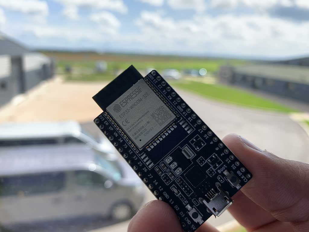
ESP32 is a series of microcontrollers from Espressif Systeme with integrated support for Wi-Fi and Bluetooth (up to LE 5.0 and 5.11). It is an evolution of the ESP8266.
ESP32 is capable of functioning reliably in industrial environments, with an operating temperature ranging from –40°C to +125°C. Powered by advanced calibration circuitries, ESP32 can dynamically remove external circuit imperfections and adapt to changes in external conditions.
ESP32 is highly-integrated with in-built antenna switches, power amplifier, low-noise receive amplifier, filters, and power management modules. ESP32 adds priceless functionality and versatility to your applications with minimal Printed Circuit Board (PCB) requirements.
ESP32 can perform as a complete standalone system or as a slave device to a host MCU, reducing communication stack overhead on the main application processor. ESP32 can interface with other systems to provide Wi-Fi and Bluetooth functionality through its SPI / SDIO or I2C / UART interfaces.
Engineered for mobile devices, wearable electronics and IoT applications, ESP32 achieves ultra-low power consumption with a combination of several types of proprietary software. ESP32 also includes state-of-the-art features, such as fine-grained clock gating, various power modes and dynamic power scaling.
Credit : Espressif Systeme
Installing the ESP32 on the Arduino IDE
To use the ESP32 with the Arduino software it is necessary to add the board to the software. All the steps are done on a Mac, there may be some inconsistencies with another operating system.
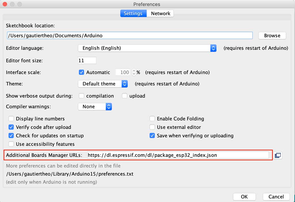
To do this, open the Arduino application and go to Arduino > Preferences then paste this link into this location:
https://dl.espressif.com/dl/package_esp32_index.json
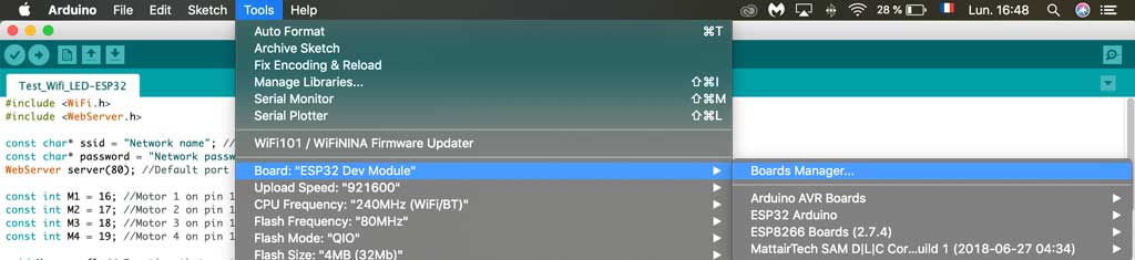
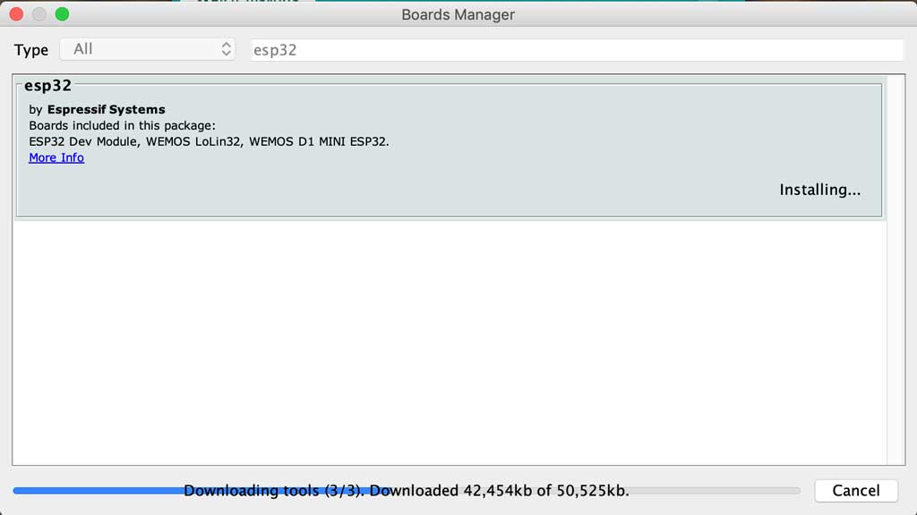
Once you have registered this new link you should also download the boards. To do this you need to open the tools tab > board manager. Type ESP32 in the search bar and download the pack
Installing the CP210x Driver
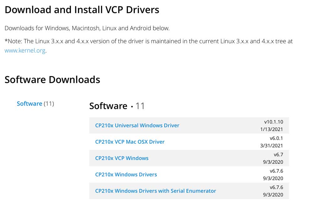
In order to interface with an ESP32 it is necessary to install a driver to make the link between UART and USB. To do this you need to go to this link and download the appropriate driver for your computer.
https://www.silabs.com/developers/usb-to-uart-bridge-vcp-drivers
When you have downloaded the file you just have to execute it and then your computer has to restart once the driver is installed.
The installation
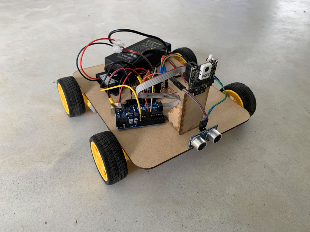
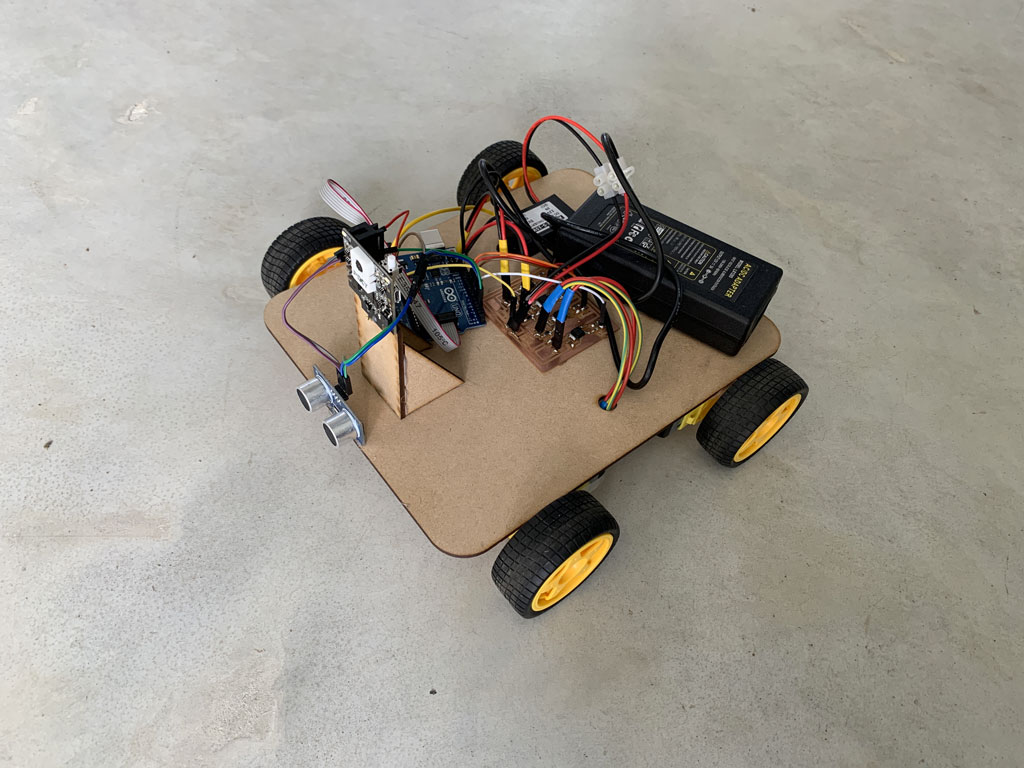
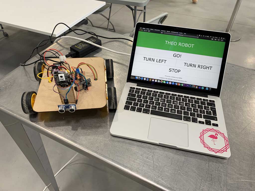
The goal of the week was to control my little robot with a wireless “remote control”.
For more information click here
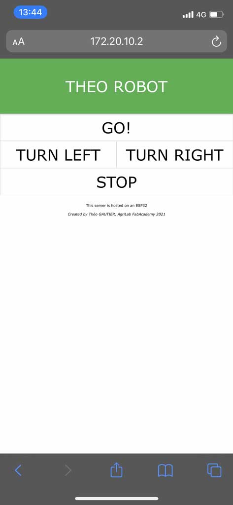
Creation of the web page
As previously mentioned I would like to control my wireless robot with a wifi connection. For that I need a web interface that would allow me to control my robot remotely. I followed the tutorials of Tommy des rochers (https://tommydesrochers.com) for how to create an HTML interface compatible with an ESP 32.
In this video he explains very quickly and simply how to create an HTML page (it’s in French). To create a rather nice environment he uses the website W3school.com. This site creates templates, so it is very fast to create an interface with a correct style simply and free. After saving the link in your text file, you can call up the templates already created for you.
Here is the code to recreate a page similar to mine. You can change the styles very easily by going to the W3school website and change the references so that your site corresponds to your expectations.
<!SERVER HTML>

<html lang='fr'>

  <head>
    <title>Server ESP32</title> //Title that your page will have on your browser's tab
    <meta http-equiv='refresh' content='60' name='viewport' content='width=device-width, initial-scale=1' charset='UTF-8' /> // Instruction line for updating your page
    <link rel='stylesheet' href='https://www.w3schools.com/w3css/4/w3.css'> // Line to link the W3school templates to your page
  </head>

   <body>
    <div class='w3-card w3-green w3-padding-small w3-jumbo w3-center'> // Line that indicates that the background of your title will be green, with a Jumbo text in the middle
    <p> THEO ROBOT :</p> // Title on the page
    </div>

    <div class='w3-bar'> // This sets the following objects to be in a horizontal line
      <a href='/go' class='w3-bar-item w3-button w3-border w3-jumbo' style='width:100%; height:50%;'>GO!</a> // This line means that you have a button with an outline, with "GO" written in the centre in jumbo type. Also when selected it will send to the /go page. It uses all the horizontal space on the line

      <a href='/left' class='w3-bar-item w3-button w3-border w3-jumbo' style='width:50%; height:25%;'>TURN LEFT</a> // This line means that you have a button with an outline, with "TURN LEFT" written in the centre in jumbo type. Also when selected it will send to the /left page. It uses half of the horizontal space on the line

      <a href='/right' class='w3-bar-item w3-button w3-border w3-jumbo' style='width:50%; height:25%;'>TURN RIGHT</a> // This line means that you have a button with an outline, with "TURN RIGHT" written in the centre in jumbo type. Also when selected it will send to the /right page. It uses half of the horizontal space on the line

      <a href='/stop' class='w3-bar-item w3-button w3-border w3-jumbo' style='width:100%; height:50%;'>STOP!</a> // This line means that you have a button with an outline, with "STOP" written in the centre in jumbo type. Also when selected it will send to the /stop page. It uses all the horizontal space on the line
    </div>


    <div class='w3-center w3-padding-16'> // This means that the text that follows will be centred and sparsely spaced.
      <p>This server is hosted on an ESP32</p> // Normal text
      <i>Created by Théo GAUTIER, AgriLab FabAcademy 2021 </i> // Text written in italics
    </div>
   </body>

<html>
This interface has the advantage of working equally well on computer, tablet or smartphone
The code in C++
Now that our web page is functional, we need to insert it into the C++ code to be used by the ESP32. The code being in HTML and the instructions in Arduino in C++ we have to find a way for the server to be read by the microcontroller. To do this, the technique used by Tommy des Rochers is to use the String function. By doing this, the ESP32 can host the server locally and can therefore interact with a web page.
#include <WiFi.h>
#include <WebServer.h>

const char* ssid = "Network name"; // Network name
const char* password = "Network password"; // Network password
WebServer server(80); //Default port for the ESP32 server relationship

const int M1 = 16; //Motor 1 on pin 16
const int M2 = 17; //Motor 2 on pin 17
const int M3 = 18; //Motor 3 on pin 18
const int M4 = 19; //Motor 4 on pin 19

void Homepage() // Function that contains my server and serves as my homepage
{
  String page = "<!SERVER html>"; // The lines in my HTML server preceded by the string function so that it is readable by the ESP32

    page += "<html lang='fr'>";

    page += "<head>";
    page += "    <title>Server ESP32</title>";
    page += "    <meta http-equiv='refresh' content='60' name='viewport' content='width=device-width, initial-scale=1' charset='UTF-8' />";
    page += "    <link rel='stylesheet' href='https://www.w3schools.com/w3css/4/w3.css'>";
    page += "</head>";

    page += "<body>";
    page += "    <div class='w3-card w3-green w3-padding-small w3-jumbo w3-center'>";
    page += "    <p>THEO ROBOT </p>";
    page += "    </div>";

    page += "    <div class='w3-bar'>";
    page += "        <a href='/go' class='w3-bar-item w3-button w3-border w3-jumbo' style='width:100%; height:50%;'>GO!</a>";
    page += "        <a href='/left' class='w3-bar-item w3-button w3-border w3-jumbo' style='width:50%; height:50%;'>TURN LEFT</a>";
    page += "        <a href='/right' class='w3-bar-item w3-button w3-border w3-jumbo' style='width:50%; height:50%;'>TURN RIGHT</a>";
    page += "        <a href='/stop' class='w3-bar-item w3-button w3-border w3-jumbo' style='width:100%; height:50%;'>STOP</a>";
    page += "    </div>";

    page += "    <div class='w3-center w3-padding-16'>";
    page += "        <p>This server is hosted on an ESP32</p>";
    page += "        <i>Created by Théo GAUTIER, AgriLab FabAcademy 2021</i>";
    page += "    </div>";

    page += "</body>";

    page += "</html>";

    server.setContentLength(page.length()); //This allows the ESP32 to know the length of the website, which allows faster communication
    server.send(200, "text/html", page); // Enables data to be sent
}

void NotFound() // Function that writes to the user "404 Not found" if a page is unknown
{
    server.send(404, "text/plain", "404: Not found");
}

void go() //Function that allows the robot to move forward, all motors are on
{
    digitalWrite(M1, HIGH);
    digitalWrite(M2, HIGH);
    digitalWrite(M3, HIGH);
    digitalWrite(M4, HIGH);
    server.sendHeader("Location","/"); // This then links to the home page
    server.send(303); // Command that tells the server it is doing a redirect
}

void stop() //Function that allows the robot to stop, all motors are off
{
    digitalWrite(M1, LOW);
    digitalWrite(M2, LOW);
    digitalWrite(M3, LOW);
    digitalWrite(M4, LOW);
    server.sendHeader("Location","/"); // This then links to the home page
    server.send(303); // Command that tells the server it is doing a redirect
}

void left() //Function that allows the robot to turn left by stopping motors 1 and 2
{
    digitalWrite(M1, LOW);
    digitalWrite(M2, LOW);
    digitalWrite(M3, HIGH);
    digitalWrite(M4, HIGH);
    server.sendHeader("Location","/"); // This then links to the home page
    server.send(303); // Command that tells the server it is doing a redirect
}

void right() // Function that allows the robot to turn right by stopping motors 3 and 4
{
    digitalWrite(M1, HIGH);
    digitalWrite(M2, HIGH);
    digitalWrite(M3, LOW);
    digitalWrite(M4, LOW);
    server.sendHeader("Location","/"); // This then links to the home page
    server.send(303); // Command that tells the server it is doing a redirect
}

void setup()
{
  Serial.begin(115200);
  delay(1000); // Delay 1s
  Serial.println("\n"); // Make a line break in the serial monitor

  pinMode(M1,OUTPUT); // Says that M1 is an output
  pinMode(M2,OUTPUT); // Says that M2 is an output
  pinMode(M3,OUTPUT); // Says that M3 is an output
  pinMode(M4,OUTPUT); // Says that M4 is an output
  digitalWrite(M1, LOW); // Set M1 to stop
  digitalWrite(M2, LOW); // Set M2 to stop
  digitalWrite(M3, LOW); // Set M3 to stop
  digitalWrite(M4, LOW); // Set M4 to stop

  WiFi.begin(ssid, password); // Function to start the wifi connection
  Serial.print("Connection in progress..."); // Print on the serial monitor "Connection in progress..."

  while(WiFi.status() != WL_CONNECTED) // As long as the connection to the network has not been established then print a dot every second
  {
    Serial.print(".");
    delay(1000);
  }

  Serial.println("\n");  // Make a line break in the serial monitor
  Serial.println("Connection established!");  // Print on the serial monitor "Connection established!"
  Serial.print("Adresse IP: ");   // Print on the serial monitor "Adresse IP:"
  Serial.println(WiFi.localIP()); // Print on the serial monitor the local IP


  server.on("/", Homepage); // When the server is on "/" then do the homepage function
  server.on("/go", go); // When the server is on "/go" then do the go function
  server.on("/left", left); // When the server is on "/left" then do the left function
  server.on("/right", right); // When the server is on "/right" then do the right function
  server.on("/stop", stop); // When the server is on "/stop" then do the stop function
  server.onNotFound(NotFound); // When the server is not found then do the NotFound function
  server.begin(); // Start the server

  Serial.println("Active web server!"); // Print on the serial monitor "Active web server!"

}

void loop()
{
  server.handleClient(); // Manage the user who is connected to the server
}
For more information click here
The server hosted on the ESP32 allows communication between a web interface and a board. The ESP32 is connected to my own wifi network created by my iPhone. Once on the web page with my Mac or iPhone I can interact with the ESP32 by clicking on the buttons that will then perform the registered functions. This is how I can drive my robot with an ESP32 and a wifi connection.
Video ESP32
- Musique : Patrick Abrial - Misirlou*
- A big thank you to Anthonio for having put his talents as a cameraman to good use, it allowed us to have a spectacular result*
Programming on Arduino
Not knowing anything about programming and to start very simply, in week 7 I only blinked my LED which is on my board. This week I decided to add a little more complexity and use my button. I would like to make a counter with my button and if the person using this counter presses the button for a long time then the red LED blinks.
To start understanding the basics our instructor Florent gave us a lecture. During this class he taught us the basics of programming and introduced us to understand the lines of code a little better. At the end of the workshop he helped us to write our own code with the librairy already present on the Arduino software.
For this I made a mix between the example to make an LED blink and the example to read a digital data. After a few tries I managed to realize my own function to count by clicking on the button and make my LED blink.
Here is the final result:
int toto = 0;
int pushButton = 5;
int LED = 2;
bool test = false;

void setup() {
  // put your setup code here, to run once:
  Serial.begin(9600);
  pinMode(pushButton, INPUT);
  pinMode(LED, OUTPUT);
  digitalWrite (LED, 1);
  delay (300);
}

void loop() {
  // put your main code here, to run repeatedly:
  int buttonState = digitalRead(pushButton);
  delay (500);
  // Serial.println(toto);
  Serial.println(pushButton);
  if (buttonState == 0) {

    digitalWrite (LED, 1);
     delay (500);
     digitalWrite (LED, 0);
      if (test == false) {
        totoplus1();
        test = true;
      }
  }
  else {
    digitalWrite (LED, 0);
    test = false;
  }
}


void totoplus1() {
  toto++;
}
Let me explain in a few words what this code is.
First of all I initiated my variable (toto), my output (LED on pin 2) and my input (button on pin 5).
Then we enter the setup function. This function is performed only once and is executed only at startup. In my code we see that I take information of the state of the button and the LED that I light it during 300 ms.
Then we enter in a loop. This loop is infinite and continues to execute the program as long as we don’t tell it to stop. In my example the loop starts by reading the state of the button, waits 500 ms and then prints it. After that it enters an “if” function. In my case the condition is that if the button is equal to 0 (button pressed) then the LED must be blinked. Moreover, if the test is false, then the totoplus1 function must be called. Otherwise, if my conditions are not fulfilled, nothing happens, the LED does not light up and the test remains false.
Finally we can see a function at the end. Totoplus1 allows to add 1 to the variable toto. The symbols ++ correspond to do + 1. The “toto” function is therefore used to increment by 1 each time the button is pressed.
Why “toto”?
In France the name “toto” is often used as a joke. In my case I didn’t know what to call my function so I named it too, it’s quick to write and easy to remember ;)
Programming on PlatformIO
To see another programming environment I decided to use the PlatformIO software from Visual Studio Code. To do this, you have to go to the Visual Studio Code website and download the software. This application is compatible with all OS (Mac, Windows or Linux). Once downloaded, you must register the PlatformIO extension.
Attention, PlatformIO does not recognize the SAMD11C that’s why I used an Arduino Uno to try this software.

When you have saved the extension, just open it and follow this tutorial:
- Click on new project (1)
- Name your project, select your board and choose the location to save your project (2)
- Click on the “main.ccp” menu to open the code writing window (3)
- Write in your code. For my part, I retrieved the code to make an LED blink in the Arduino library. I only changed the output pin so that the LED already present on pin 13 of the Arduino lights up (4)
- Click on “Upload”. This is the arrow symbol at the bottom left of your screen (5)
- The application terminal displays the success of the upload (6)
Hero shots
Group assignment
For the group assignment we decided to compare several kinds of microcontrollers. We decided to take the SAMD11C, the arduino ATmega368 and the rasberry Pi. Here is the comparison table of these components.
| Configuration Summary | SAMD11C-14 pin SOIC | Arduino Uno - ATmega328P | Rasberry Pi |
|---|---|---|---|
| Number of pins | 14 | 28 | |
| Number of I/O pins | 12 | 14 Digital I/O Pins; 6 PWM Digital I/O Pins; 6 Analog Input Pins | |
| Flash memory | 16 KB | 32 KB where 0.5 KB are taken by the bootloader | |
| SRAM | 4 KB | 2 KB | |
| Clock Speed | 16 MHz | ||
| Time counter (TC) | 2 | ||
| Output channels for TC | 2 | ||
| Timer Counter for Control (TCC) | 1 | ||
| Output channels per TCC | 8 | ||
| Direct memory access channels | 6 | ||
| USB interface | Yes | ||
| Serial Communication Interface (SERCOM) | 2 | ||
| Analog-to-Digital Converter (ADC) channels | 5 | ||
| Analog Comparators (AC) | 2 | ||
| Digital-to-Analog Converter (DAC) channels | 1 | ||
| Real-Time Counter (RTC) | Yes | ||
| RTC Alarms | 1 | ||
| RTC compare values | 1 32-bit value or 2 16-bit values | ||
| External Interrut Lines | 8 | ||
| Peripheral Touch Controller (PTC) channels for mutual capacitance | 12 (4x3) | ||
| Peripheral Touch Controller (PTC) channels for self capacitance | 7 | ||
| Maximum CPU frequency | 48MHz | ||
| Packages | SOIC | 28P3 | |
| Oscillators | 32.768kHz crystal oscillator (XOSC32K) 0.4-32MHz crystal oscillator (XOSC) 32.768kHzinternal oscillator (OSC32K)32kHz ultra-low-power internal oscillator (OSCULP32K) 8MHz high-accuracy internal oscillator (OSC8M) 48MHz Digital Frequency Locked Loop (DFLL48M) 96MHz Fractional Digital Phased Locked Loop (FDPLL96M) | ||
| Event System channels | 6 | ||
| SW Debug Interface | Yes | ||
| Watchdog Timer (WDT) | Yes | ||
| Temperature range | -40 to 85°C | -40°C to 85°C | |
| Operating voltage | 1,62 to 3,63 V | 1.8 to 5.5 V | |
| Processor | ARM Cortex-M0+ CPU running at up to 48MHz |
Raspberry Pi 4 specifications table:
| GPIO | Pull | ALT0 | ALT1 | ALT2 | ALT3 | ALT4 | ALT5 |
|---|---|---|---|---|---|---|---|
| 0 | HIGH | SDA0 | SA5 | PCLK | SPI3_CE0_N | TXD2 | SDA6 |
| 1 | HIGH | SCL0 | SA4 | DE | SPI3_MISO | RXD2 | SCL6 |
| 2 | HIGH | SDA1 | SA3 | LCD_VSYNC | SPI3_MOSI | CTS2 | SDA3 |
| 3 | HIGH | SCL1 | SA2 | LCD_HSYNC | SPI3_SCLK | RTS2 | SCL3 |
| 4 | HIGH | GPCLK0 | SA1 | DPI_D0 | SPI4_CE0_N | TXD3 | SDA3 |
| 5 | HIGH | GPCLK1 | SA0 | DPI_D1 | SPI4_MISO | RXD3 | SCL3 |
| 6 | HIGH | GPCLK2 | SOE_N | DPI_D2 | SPI4_MOSI | CTS3 | SDA4 |
| 7 | HIGH | SDA0 | SA5 | PCLK | SPI4_CE0_N | RTS3 | SCL4 |
| 8 | HIGH | SDA0 | SA5 | PCLK | SPI3_CE0_N | TXD2 | SDA4 |
| 9 | LOW | SPIO_MISO | SD1 | DPI_D5 | - | RXD4 | SCL4 |
| 10 | LOW | SDA0 | SA5 | PCLK | SPI3_CE0_N | TXD2 | SDA6 |
| 11 | LOW | SDA0 | SA5 | PCLK | SPI3_CE0_N | TXD2 | SDA6 |
| 12 | LOW | SDA0 | SA5 | PCLK | SPI3_CE0_N | TXD2 | SDA6 |
| 13 | LOW | SDA0 | SA5 | PCLK | SPI3_CE0_N | TXD2 | SDA6 |
| 14 | LOW | SDA0 | SA5 | PCLK | SPI3_CE0_N | TXD2 | SDA6 |
| 15 | LOW | SDA0 | SA5 | PCLK | SPI3_CE0_N | TXD2 | SDA6 |
| 16 | LOW | SDA0 | SA5 | PCLK | SPI3_CE0_N | TXD2 | SDA6 |
| 17 | LOW | SDA0 | SA5 | PCLK | SPI3_CE0_N | TXD2 | SDA6 |
| 18 | LOW | SDA0 | SA5 | PCLK | SPI3_CE0_N | TXD2 | SDA6 |
| 19 | LOW | SDA0 | SA5 | PCLK | SPI3_CE0_N | TXD2 | SDA6 |
| 20 | LOW | SDA0 | SA5 | PCLK | SPI3_CE0_N | TXD2 | SDA6 |
| 21 | LOW | SDA0 | SA5 | PCLK | SPI3_CE0_N | TXD2 | SDA6 |
| 22 | LOW | SDA0 | SA5 | PCLK | SPI3_CE0_N | TXD2 | SDA6 |
| 23 | LOW | SDA0 | SA5 | PCLK | SPI3_CE0_N | TXD2 | SDA6 |
| 24 | LOW | SDA0 | SA5 | PCLK | SPI3_CE0_N | TXD2 | SDA6 |
| 25 | LOW | SDA0 | SA5 | PCLK | SPI3_CE0_N | TXD2 | SDA6 |
| 26 | LOW | SDA0 | SA5 | PCLK | SPI3_CE0_N | TXD2 | SDA6 |
| 27 | LOW | SDA0 | SA5 | PCLK | SPI3_CE0_N | TXD2 | SDA6 |
Micro:bit - programming microcontroller Nordic nRF51822
During the bootcamp week, Elina and me discovered a little bit about micro:bit, that’s why we reused this board for this week. On micro:bit website, there is an interface, makecode editor to play with code as blocks. Elina made the programm with blockly language, that bring to a JavaScript code. The micro:bit board is processed by a MCU Nordic nRF51822.
The programmation of this microcontroller is the second microcontroller programmed for the group assignment.
To test the editor, She put the blocks to make the board print “hello” at the end and when we push the A button, it make a heart shape blink two times. The button B clear the LEDs.

We can also check the code in JavaScript:
input.onButtonPressed(Button.A, function () {
    for (let index = 0; index < 2; index++) {
        basic.showIcon(IconNames.Heart)
        basic.pause(1000)
        basic.showLeds(`
            . . . . .
            . . . . .
            . . . . .
            . . . . .
            . . . . .
            `)
    }
})
input.onButtonPressed(Button.B, function () {
    basic.clearScreen()
})
basic.showString("Hello!")
basic.forever(function () {

})
She did not write the code in JavaScript, but she just checked to know what is going on in with this language and blockly she used.
When the code is done, we just need to download the file and then copy it in the micro:bit board, plugged to my computer.
And here is the result:
This way of working is nice to learn quickly some code, and very nice to see, but it is pretty limited, to the micro:bit board.
ESP32
Théo test also the ESP32. Here is his work
During the Interface and application programming week I also programmed an ESP32. This microcontroller is different from the others already mentioned. Here are the different steps to program with an ESP32 on the Arduino software on a Mac.
The ESP 32 in a few words
ESP32 is a series of microcontrollers from Espressif Systeme with integrated support for Wi-Fi and Bluetooth (up to LE 5.0 and 5.11). It is an evolution of the ESP8266.
ESP32 is capable of functioning reliably in industrial environments, with an operating temperature ranging from –40°C to +125°C. Powered by advanced calibration circuitries, ESP32 can dynamically remove external circuit imperfections and adapt to changes in external conditions.
ESP32 is highly-integrated with in-built antenna switches, power amplifier, low-noise receive amplifier, filters, and power management modules. ESP32 adds priceless functionality and versatility to your applications with minimal Printed Circuit Board (PCB) requirements.
ESP32 can perform as a complete standalone system or as a slave device to a host MCU, reducing communication stack overhead on the main application processor. ESP32 can interface with other systems to provide Wi-Fi and Bluetooth functionality through its SPI / SDIO or I2C / UART interfaces.
Engineered for mobile devices, wearable electronics and IoT applications, ESP32 achieves ultra-low power consumption with a combination of several types of proprietary software. ESP32 also includes state-of-the-art features, such as fine-grained clock gating, various power modes and dynamic power scaling.
Credit : Espressif Systeme
Installing the ESP32 on the Arduino IDE
To use the ESP32 with the Arduino software it is necessary to add the board to the software. All the steps are done on a Mac, there may be some inconsistencies with another operating system.
To do this, open the Arduino application and go to Arduino > Preferences then paste this link into this location:
https://dl.espressif.com/dl/package_esp32_index.json
Once you have registered this new link you should also download the boards. To do this you need to open the tools tab > board manager. Type ESP32 in the search bar and download the pack
Installing the CP210x Driver
In order to interface with an ESP32 it is necessary to install a driver to make the link between UART and USB. To do this you need to go to this link and download the appropriate driver for your computer.
https://www.silabs.com/developers/usb-to-uart-bridge-vcp-drivers
When you have downloaded the file you just have to execute it and then your computer has to restart once the driver is installed.
The installation
The goal of the week was to control my little robot with a wireless “remote control”.
For more information click here
Creation of the web page
As previously mentioned I would like to control my wireless robot with a wifi connection. For that I need a web interface that would allow me to control my robot remotely. I followed the tutorials of Tommy des rochers (https://tommydesrochers.com) for how to create an HTML interface compatible with an ESP 32.
In this video he explains very quickly and simply how to create an HTML page (it’s in French). To create a rather nice environment he uses the website W3school.com. This site creates templates, so it is very fast to create an interface with a correct style simply and free. After saving the link in your text file, you can call up the templates already created for you.
Here is the code to recreate a page similar to mine. You can change the styles very easily by going to the W3school website and change the references so that your site corresponds to your expectations.
<!SERVER HTML>

<html lang='fr'>

  <head>
    <title>Server ESP32</title> //Title that your page will have on your browser's tab
    <meta http-equiv='refresh' content='60' name='viewport' content='width=device-width, initial-scale=1' charset='UTF-8' /> // Instruction line for updating your page
    <link rel='stylesheet' href='https://www.w3schools.com/w3css/4/w3.css'> // Line to link the W3school templates to your page
  </head>

   <body>
    <div class='w3-card w3-green w3-padding-small w3-jumbo w3-center'> // Line that indicates that the background of your title will be green, with a Jumbo text in the middle
    <p> THEO ROBOT :</p> // Title on the page
    </div>

    <div class='w3-bar'> // This sets the following objects to be in a horizontal line
      <a href='/go' class='w3-bar-item w3-button w3-border w3-jumbo' style='width:100%; height:50%;'>GO!</a> // This line means that you have a button with an outline, with "GO" written in the centre in jumbo type. Also when selected it will send to the /go page. It uses all the horizontal space on the line

      <a href='/left' class='w3-bar-item w3-button w3-border w3-jumbo' style='width:50%; height:25%;'>TURN LEFT</a> // This line means that you have a button with an outline, with "TURN LEFT" written in the centre in jumbo type. Also when selected it will send to the /left page. It uses half of the horizontal space on the line

      <a href='/right' class='w3-bar-item w3-button w3-border w3-jumbo' style='width:50%; height:25%;'>TURN RIGHT</a> // This line means that you have a button with an outline, with "TURN RIGHT" written in the centre in jumbo type. Also when selected it will send to the /right page. It uses half of the horizontal space on the line

      <a href='/stop' class='w3-bar-item w3-button w3-border w3-jumbo' style='width:100%; height:50%;'>STOP!</a> // This line means that you have a button with an outline, with "STOP" written in the centre in jumbo type. Also when selected it will send to the /stop page. It uses all the horizontal space on the line
    </div>


    <div class='w3-center w3-padding-16'> // This means that the text that follows will be centred and sparsely spaced.
      <p>This server is hosted on an ESP32</p> // Normal text
      <i>Created by Théo GAUTIER, AgriLab FabAcademy 2021 </i> // Text written in italics
    </div>
   </body>

<html>
This interface has the advantage of working equally well on computer, tablet or smartphone
The code in C++
Now that our web page is functional, we need to insert it into the C++ code to be used by the ESP32. The code being in HTML and the instructions in Arduino in C++ we have to find a way for the server to be read by the microcontroller. To do this, the technique used by Tommy des Rochers is to use the String function. By doing this, the ESP32 can host the server locally and can therefore interact with a web page.
#include <WiFi.h>
#include <WebServer.h>

const char* ssid = "Network name"; // Network name
const char* password = "Network password"; // Network password
WebServer server(80); //Default port for the ESP32 server relationship

const int M1 = 16; //Motor 1 on pin 16
const int M2 = 17; //Motor 2 on pin 17
const int M3 = 18; //Motor 3 on pin 18
const int M4 = 19; //Motor 4 on pin 19

void Homepage() // Function that contains my server and serves as my homepage
{
  String page = "<!SERVER html>"; // The lines in my HTML server preceded by the string function so that it is readable by the ESP32

    page += "<html lang='fr'>";

    page += "<head>";
    page += "    <title>Server ESP32</title>";
    page += "    <meta http-equiv='refresh' content='60' name='viewport' content='width=device-width, initial-scale=1' charset='UTF-8' />";
    page += "    <link rel='stylesheet' href='https://www.w3schools.com/w3css/4/w3.css'>";
    page += "</head>";

    page += "<body>";
    page += "    <div class='w3-card w3-green w3-padding-small w3-jumbo w3-center'>";
    page += "    <p>THEO ROBOT </p>";
    page += "    </div>";

    page += "    <div class='w3-bar'>";
    page += "        <a href='/go' class='w3-bar-item w3-button w3-border w3-jumbo' style='width:100%; height:50%;'>GO!</a>";
    page += "        <a href='/left' class='w3-bar-item w3-button w3-border w3-jumbo' style='width:50%; height:50%;'>TURN LEFT</a>";
    page += "        <a href='/right' class='w3-bar-item w3-button w3-border w3-jumbo' style='width:50%; height:50%;'>TURN RIGHT</a>";
    page += "        <a href='/stop' class='w3-bar-item w3-button w3-border w3-jumbo' style='width:100%; height:50%;'>STOP</a>";
    page += "    </div>";

    page += "    <div class='w3-center w3-padding-16'>";
    page += "        <p>This server is hosted on an ESP32</p>";
    page += "        <i>Created by Théo GAUTIER, AgriLab FabAcademy 2021</i>";
    page += "    </div>";

    page += "</body>";

    page += "</html>";

    server.setContentLength(page.length()); //This allows the ESP32 to know the length of the website, which allows faster communication
    server.send(200, "text/html", page); // Enables data to be sent
}

void NotFound() // Function that writes to the user "404 Not found" if a page is unknown
{
    server.send(404, "text/plain", "404: Not found");
}

void go() //Function that allows the robot to move forward, all motors are on
{
    digitalWrite(M1, HIGH);
    digitalWrite(M2, HIGH);
    digitalWrite(M3, HIGH);
    digitalWrite(M4, HIGH);
    server.sendHeader("Location","/"); // This then links to the home page
    server.send(303); // Command that tells the server it is doing a redirect
}

void stop() //Function that allows the robot to stop, all motors are off
{
    digitalWrite(M1, LOW);
    digitalWrite(M2, LOW);
    digitalWrite(M3, LOW);
    digitalWrite(M4, LOW);
    server.sendHeader("Location","/"); // This then links to the home page
    server.send(303); // Command that tells the server it is doing a redirect
}

void left() //Function that allows the robot to turn left by stopping motors 1 and 2
{
    digitalWrite(M1, LOW);
    digitalWrite(M2, LOW);
    digitalWrite(M3, HIGH);
    digitalWrite(M4, HIGH);
    server.sendHeader("Location","/"); // This then links to the home page
    server.send(303); // Command that tells the server it is doing a redirect
}

void right() // Function that allows the robot to turn right by stopping motors 3 and 4
{
    digitalWrite(M1, HIGH);
    digitalWrite(M2, HIGH);
    digitalWrite(M3, LOW);
    digitalWrite(M4, LOW);
    server.sendHeader("Location","/"); // This then links to the home page
    server.send(303); // Command that tells the server it is doing a redirect
}

void setup()
{
  Serial.begin(115200);
  delay(1000); // Delay 1s
  Serial.println("\n"); // Make a line break in the serial monitor

  pinMode(M1,OUTPUT); // Says that M1 is an output
  pinMode(M2,OUTPUT); // Says that M2 is an output
  pinMode(M3,OUTPUT); // Says that M3 is an output
  pinMode(M4,OUTPUT); // Says that M4 is an output
  digitalWrite(M1, LOW); // Set M1 to stop
  digitalWrite(M2, LOW); // Set M2 to stop
  digitalWrite(M3, LOW); // Set M3 to stop
  digitalWrite(M4, LOW); // Set M4 to stop

  WiFi.begin(ssid, password); // Function to start the wifi connection
  Serial.print("Connection in progress..."); // Print on the serial monitor "Connection in progress..."

  while(WiFi.status() != WL_CONNECTED) // As long as the connection to the network has not been established then print a dot every second
  {
    Serial.print(".");
    delay(1000);
  }

  Serial.println("\n");  // Make a line break in the serial monitor
  Serial.println("Connection established!");  // Print on the serial monitor "Connection established!"
  Serial.print("Adresse IP: ");   // Print on the serial monitor "Adresse IP:"
  Serial.println(WiFi.localIP()); // Print on the serial monitor the local IP


  server.on("/", Homepage); // When the server is on "/" then do the homepage function
  server.on("/go", go); // When the server is on "/go" then do the go function
  server.on("/left", left); // When the server is on "/left" then do the left function
  server.on("/right", right); // When the server is on "/right" then do the right function
  server.on("/stop", stop); // When the server is on "/stop" then do the stop function
  server.onNotFound(NotFound); // When the server is not found then do the NotFound function
  server.begin(); // Start the server

  Serial.println("Active web server!"); // Print on the serial monitor "Active web server!"

}

void loop()
{
  server.handleClient(); // Manage the user who is connected to the server
}
For more information click here
The server hosted on the ESP32 allows communication between a web interface and a board. The ESP32 is connected to my own wifi network created by my iPhone. Once on the web page with my Mac or iPhone I can interact with the ESP32 by clicking on the buttons that will then perform the registered functions. This is how I can drive my robot with an ESP32 and a wifi connection.
Video ESP32
- Musique : Patrick Abrial - Misirlou*
- A big thank you to Anthonio for having put his talents as a cameraman to good use, it allowed us to have a spectacular result*
Conclusion
This week wasn’t the most fun week but you have to go through weeks like this to learn. Otherwise I was very happy to write my first function, it encourages me to learn more to be able to program my final project. I enjoyed using the PlatFormIO software but I will continue to use the Arduino software to code, this one has more libraries that can help me later on. Finally I’m happy to have tried several different languages but I’m going to focus more on the C language. This one will be very useful for my final project.
Files
- TestPlatFormIO
- TestArduino
- Code microbit
- BlinkArduino
- Code interface Processing .pde
- Arduino code ESP32 .ino
- Web page. zip