16. Interface and application programming
This week was dedicated to write a program that allows to have an interface with an input/output of our choice. For that I decided to take the prototype I already built for my first tests of my final project. For the interface I decided to build a web page that would allow me to drive my robot. For that I use an ESP32 and my motor control board made in week 12. In this documentation you will see how to drive a small robot with an ESP32 and a wifi connection. I also made an interface to communicate between a SAMD11C and my Mac. With this interface I can control the status of several LEDs.
• Group assignment :
Compare as many tool options as possible.
• Individual assignment :
Write an application that interfaces a user with an input and/or output device that you made
Hero video
- Musique : Patrick Abrial - Misirlou*
- A big thank you to Anthonio for having put his talents as a cameraman to good use, it allowed us to have a spectacular result*
Individual assignement
The ESP 32 in a few words
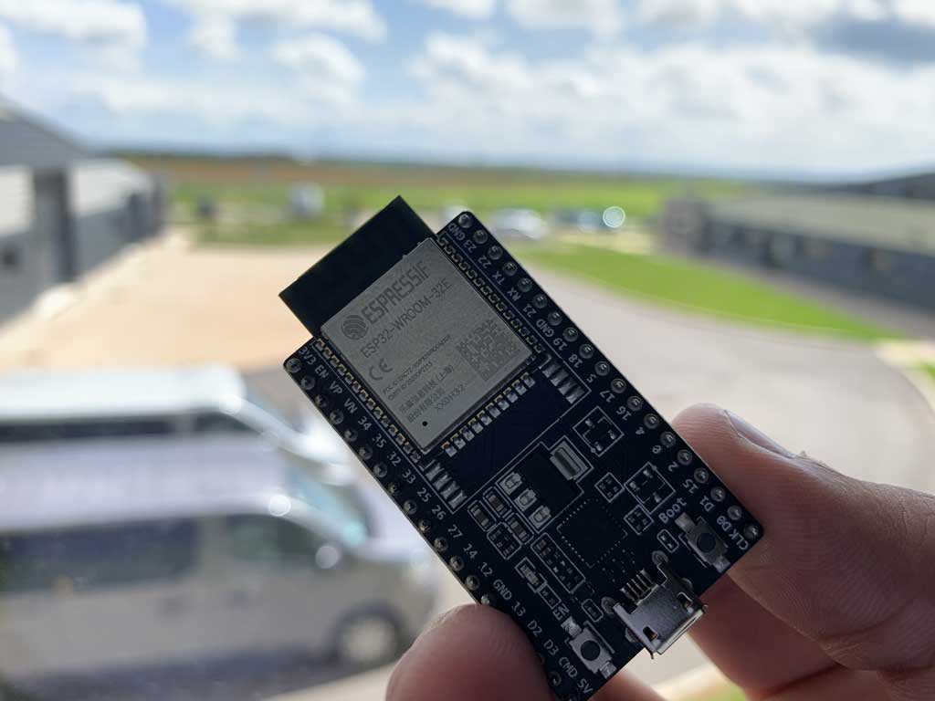
ESP32 is a series of microcontrollers from Espressif Systeme with integrated support for Wi-Fi and Bluetooth (up to LE 5.0 and 5.11). It is an evolution of the ESP8266.
ESP32 is capable of functioning reliably in industrial environments, with an operating temperature ranging from –40°C to +125°C. Powered by advanced calibration circuitries, ESP32 can dynamically remove external circuit imperfections and adapt to changes in external conditions.
ESP32 is highly-integrated with in-built antenna switches, power amplifier, low-noise receive amplifier, filters, and power management modules. ESP32 adds priceless functionality and versatility to your applications with minimal Printed Circuit Board (PCB) requirements.
ESP32 can perform as a complete standalone system or as a slave device to a host MCU, reducing communication stack overhead on the main application processor. ESP32 can interface with other systems to provide Wi-Fi and Bluetooth functionality through its SPI / SDIO or I2C / UART interfaces.
Engineered for mobile devices, wearable electronics and IoT applications, ESP32 achieves ultra-low power consumption with a combination of several types of proprietary software. ESP32 also includes state-of-the-art features, such as fine-grained clock gating, various power modes and dynamic power scaling.
Credit : Espressif Systeme
Installing the ESP32 on the Arduino IDE
To use the ESP32 with the Arduino software it is necessary to add the board to the software. All the steps are done on a Mac, there may be some inconsistencies with another operating system.
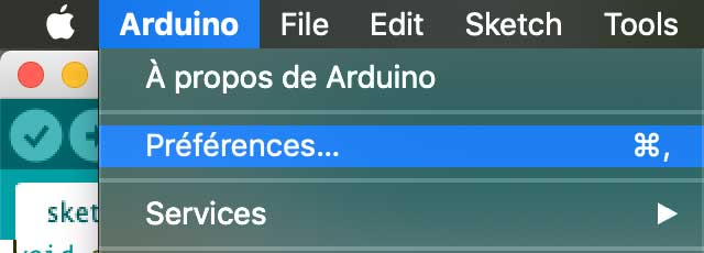
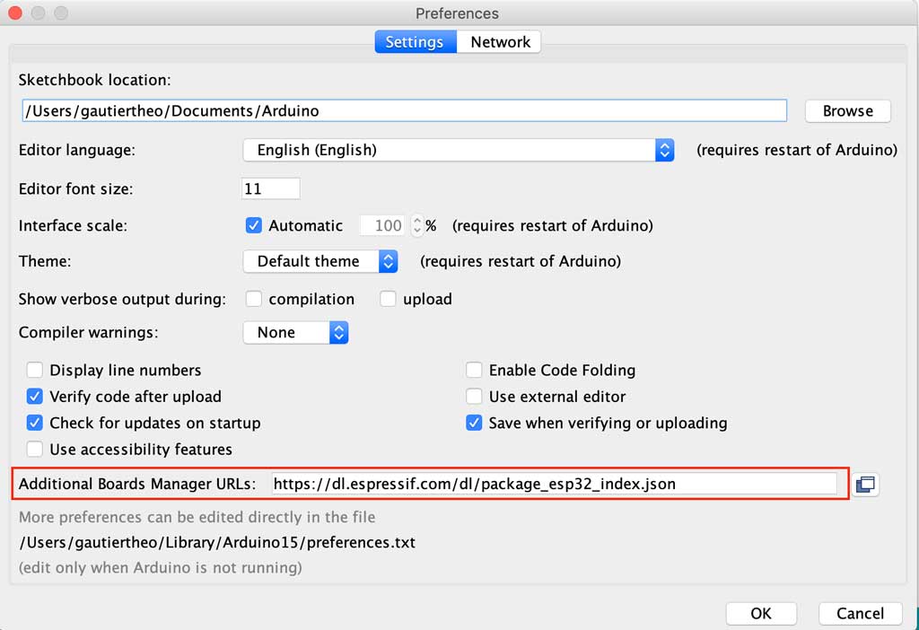
To do this, open the Arduino application and go to Arduino > Preferences then paste this link into this location:
https://dl.espressif.com/dl/package_esp32_index.json
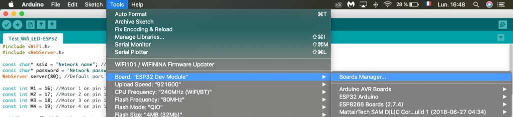
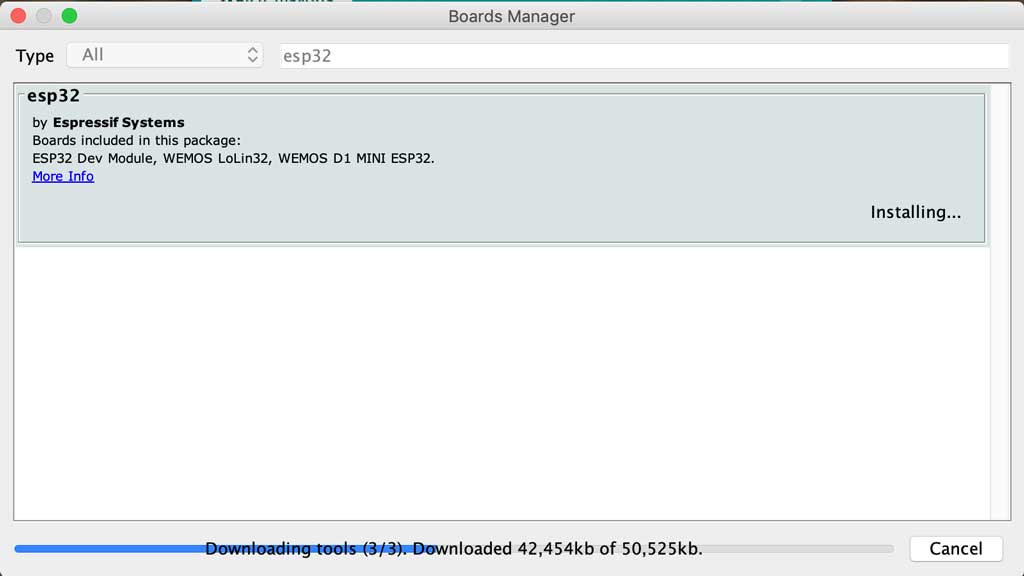
Once you have registered this new link you should also download the boards. To do this you need to open the tools tab > board manager. Type ESP32 in the search bar and download the pack
Installing the CP210x Driver
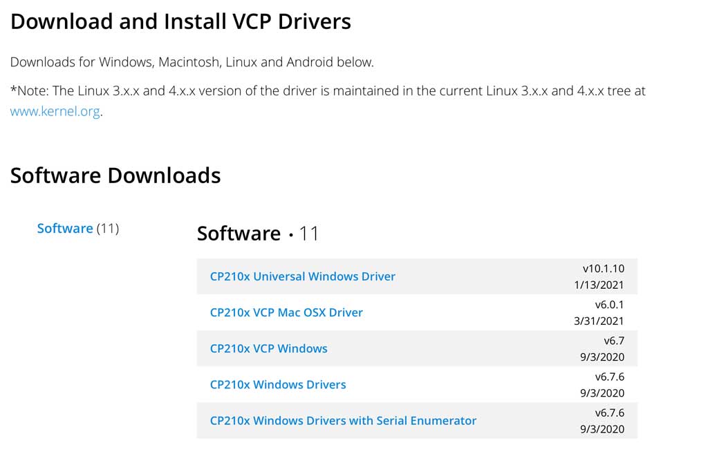
In order to interface with an ESP32 it is necessary to install a driver to make the link between UART and USB. To do this you need to go to this link and download the appropriate driver for your computer.
https://www.silabs.com/developers/usb-to-uart-bridge-vcp-drivers
When you have downloaded the file you just have to execute it and then your computer has to restart once the driver is installed.
The installation
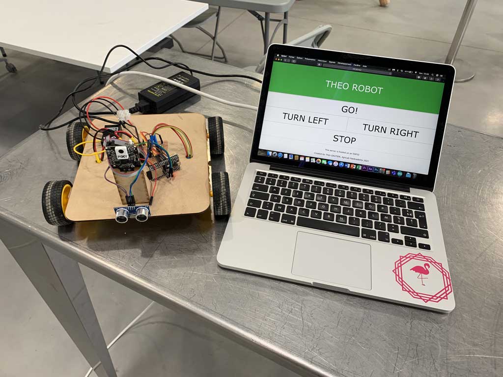
The goal of the week was to control my little robot with a wireless “remote control”.
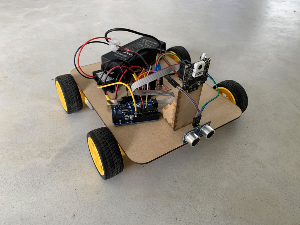
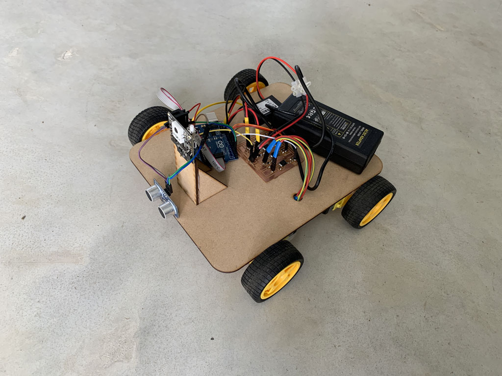
I laser cut the base of my prototype with the support for the Pixy2 camera. Then with hot glue I glued the small motors I used during the output week, the sonar discovered during the input week and the Pixy2 camera with its support.
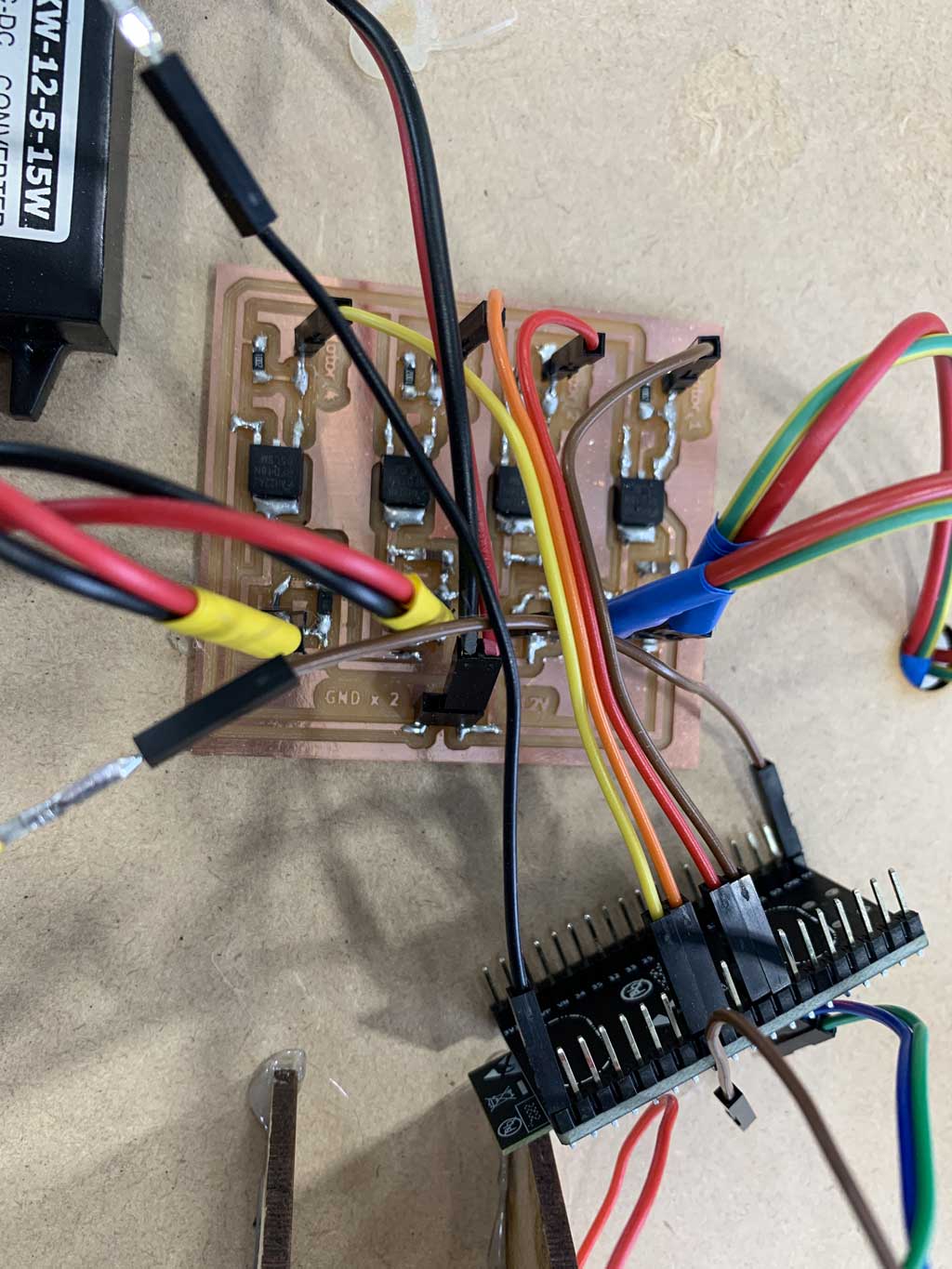
Concerning the management of the engines I used the power board I created during the output week. For the power I used a wired power supply. The batteries present at AgriLab are much too big for my little robot so to avoid a too important weight constraint I decided on a wired power source. If you want to rebuild this robot it is possible to use a battery instead.
List of materials for the construction of the prototype
- A 3mm MDF for the base
- 4 motors like this one
- 4 wheels which are supplied with the motors to transmit power to the robot and make it move
- A 12V - 5V converter to power the ESP32. I used this converter because I realized too late (once my board was finished, soldered, and flashed) that I could not use 12V to power my board.
- A motor control board to send power to the motors without going through the ESP32
- A power source to supply electricity to the robot. At first I used a 12V and 5A wire source and then I used 3 lithium batteries of 3.7V each. That allowed me to have 11,1V and 820mAh
- Connecting wires to link the elements together and ensure good information transmission
- Hot glue to fix all the elements
For this I chose the ESP32 in Wifi connection with my phone. I had to make some adaptations in order to put an ESP32 to drive the unit. Once the ESP32 was inserted in my robot I had to create a web interface to manage it.
Creation of the web page
As previously mentioned I would like to control my wireless robot with a wifi connection. For that I need a web interface that would allow me to control my robot remotely. I followed the tutorials of Tommy des rochers (https://tommydesrochers.com) for how to create an HTML interface compatible with an ESP 32.
In this video he explains very quickly and simply how to create an HTML page (it’s in French). To create a rather nice environment he uses the website W3school.com. This site creates templates, so it is very fast to create an interface with a correct style simply and free. After saving the link in your text file, you can call up the templates already created for you.
Here is the code to recreate a page similar to mine. You can change the styles very easily by going to the W3school website and change the references so that your site corresponds to your expectations.
<!SERVER HTML>
<html lang='fr'>
<head>
<title>Server ESP32</title> //Title that your page will have on your browser's tab
<meta http-equiv='refresh' content='60' name='viewport' content='width=device-width, initial-scale=1' charset='UTF-8' /> // Instruction line for updating your page
<link rel='stylesheet' href='https://www.w3schools.com/w3css/4/w3.css'> // Line to link the W3school templates to your page
</head>
<body>
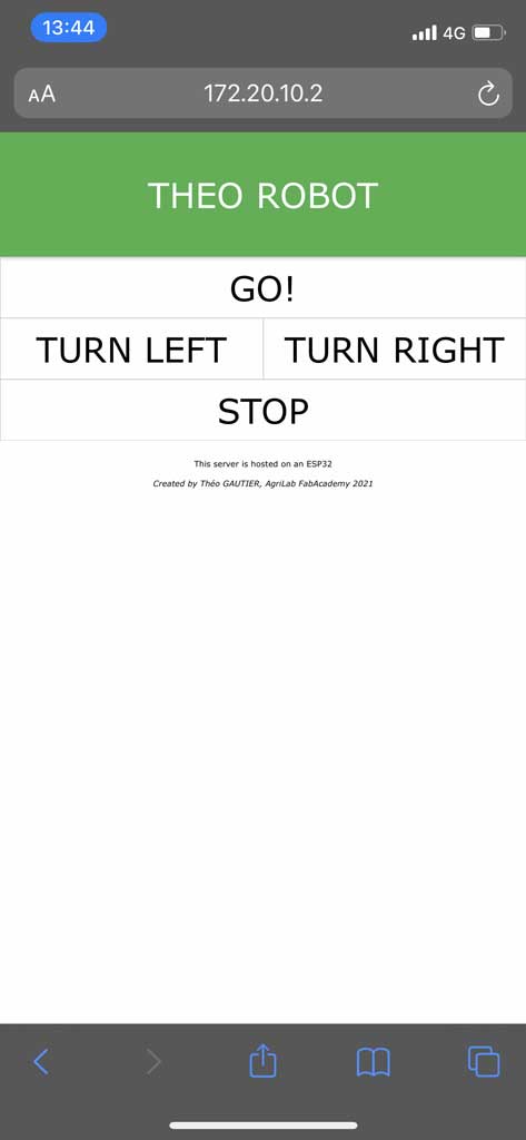
<div class='w3-card w3-green w3-padding-small w3-jumbo w3-center'> // Line that indicates that the background of your title will be green, with a Jumbo text in the middle
<p> THEO ROBOT :</p> // Title on the page
</div>
<div class='w3-bar'> // This sets the following objects to be in a horizontal line
<a href='/go' class='w3-bar-item w3-button w3-border w3-jumbo' style='width:100%; height:50%;'>GO!</a> // This line means that you have a button with an outline, with "GO" written in the centre in jumbo type. Also when selected it will send to the /go page. It uses all the horizontal space on the line
<a href='/left' class='w3-bar-item w3-button w3-border w3-jumbo' style='width:50%; height:25%;'>TURN LEFT</a> // This line means that you have a button with an outline, with "TURN LEFT" written in the centre in jumbo type. Also when selected it will send to the /left page. It uses half of the horizontal space on the line
<a href='/right' class='w3-bar-item w3-button w3-border w3-jumbo' style='width:50%; height:25%;'>TURN RIGHT</a> // This line means that you have a button with an outline, with "TURN RIGHT" written in the centre in jumbo type. Also when selected it will send to the /right page. It uses half of the horizontal space on the line
<a href='/stop' class='w3-bar-item w3-button w3-border w3-jumbo' style='width:100%; height:50%;'>STOP!</a> // This line means that you have a button with an outline, with "STOP" written in the centre in jumbo type. Also when selected it will send to the /stop page. It uses all the horizontal space on the line
</div>
<div class='w3-center w3-padding-16'> // This means that the text that follows will be centred and sparsely spaced.
<p>This server is hosted on an ESP32</p> // Normal text
<i>Created by Théo GAUTIER, AgriLab FabAcademy 2021 </i> // Text written in italics
</div>
</body>
<html>
This interface has the advantage of working equally well on computer, tablet or smartphone
The code in C++
Now that our web page is functional, we need to insert it into the C++ code to be used by the ESP32. The code being in HTML and the instructions in Arduino in C++ we have to find a way for the server to be read by the microcontroller. To do this, the technique used by Tommy des Rochers is to use the String function. By doing this, the ESP32 can host the server locally and can therefore interact with a web page.
#include <WiFi.h>
#include <WebServer.h>

const char* ssid = "Network name"; // Network name
const char* password = "Network password"; // Network password
WebServer server(80); //Default port for the ESP32 server relationship

const int M1 = 16; //Motor 1 on pin 16
const int M2 = 17; //Motor 2 on pin 17
const int M3 = 18; //Motor 3 on pin 18
const int M4 = 19; //Motor 4 on pin 19

void Homepage() // Function that contains my server and serves as my homepage
{
  String page = "<!SERVER html>"; // The lines in my HTML server preceded by the string function so that it is readable by the ESP32

    page += "<html lang='fr'>";

    page += "<head>";
    page += "    <title>Server ESP32</title>";
    page += "    <meta http-equiv='refresh' content='60' name='viewport' content='width=device-width, initial-scale=1' charset='UTF-8' />";
    page += "    <link rel='stylesheet' href='https://www.w3schools.com/w3css/4/w3.css'>";
    page += "</head>";

    page += "<body>";
    page += "    <div class='w3-card w3-green w3-padding-small w3-jumbo w3-center'>";
    page += "    <p>THEO ROBOT </p>";
    page += "    </div>";

    page += "    <div class='w3-bar'>";
    page += "        <a href='/go' class='w3-bar-item w3-button w3-border w3-jumbo' style='width:100%; height:50%;'>GO!</a>";
    page += "        <a href='/left' class='w3-bar-item w3-button w3-border w3-jumbo' style='width:50%; height:50%;'>TURN LEFT</a>";
    page += "        <a href='/right' class='w3-bar-item w3-button w3-border w3-jumbo' style='width:50%; height:50%;'>TURN RIGHT</a>";
    page += "        <a href='/stop' class='w3-bar-item w3-button w3-border w3-jumbo' style='width:100%; height:50%;'>STOP</a>";
    page += "    </div>";

    page += "    <div class='w3-center w3-padding-16'>";
    page += "        <p>This server is hosted on an ESP32</p>";
    page += "        <i>Created by Théo GAUTIER, AgriLab FabAcademy 2021</i>";
    page += "    </div>";

    page += "</body>";

    page += "</html>";

    server.setContentLength(page.length()); //This allows the ESP32 to know the length of the website, which allows faster communication
    server.send(200, "text/html", page); // Enables data to be sent
}

void NotFound() // Function that writes to the user "404 Not found" if a page is unknown
{
    server.send(404, "text/plain", "404: Not found");
}

void go() //Function that allows the robot to move forward, all motors are on
{
    digitalWrite(M1, HIGH);
    digitalWrite(M2, HIGH);
    digitalWrite(M3, HIGH);
    digitalWrite(M4, HIGH);
    server.sendHeader("Location","/"); // This then links to the home page
    server.send(303); // Command that tells the server it is doing a redirect
}

void stop() //Function that allows the robot to stop, all motors are off
{
    digitalWrite(M1, LOW);
    digitalWrite(M2, LOW);
    digitalWrite(M3, LOW);
    digitalWrite(M4, LOW);
    server.sendHeader("Location","/"); // This then links to the home page
    server.send(303); // Command that tells the server it is doing a redirect
}

void left() //Function that allows the robot to turn left by stopping motors 1 and 2
{
    digitalWrite(M1, LOW);
    digitalWrite(M2, LOW);
    digitalWrite(M3, HIGH);
    digitalWrite(M4, HIGH);
    server.sendHeader("Location","/"); // This then links to the home page
    server.send(303); // Command that tells the server it is doing a redirect
}

void right() // Function that allows the robot to turn right by stopping motors 3 and 4
{
    digitalWrite(M1, HIGH);
    digitalWrite(M2, HIGH);
    digitalWrite(M3, LOW);
    digitalWrite(M4, LOW);
    server.sendHeader("Location","/"); // This then links to the home page
    server.send(303); // Command that tells the server it is doing a redirect
}

void setup()
{
  Serial.begin(115200);
  delay(1000); // Delay 1s
  Serial.println("\n"); // Make a line break in the serial monitor

  pinMode(M1,OUTPUT); // Says that M1 is an output
  pinMode(M2,OUTPUT); // Says that M2 is an output
  pinMode(M3,OUTPUT); // Says that M3 is an output
  pinMode(M4,OUTPUT); // Says that M4 is an output
  digitalWrite(M1, LOW); // Set M1 to stop
  digitalWrite(M2, LOW); // Set M2 to stop
  digitalWrite(M3, LOW); // Set M3 to stop
  digitalWrite(M4, LOW); // Set M4 to stop

  WiFi.begin(ssid, password); // Function to start the wifi connection
  Serial.print("Connection in progress..."); // Print on the serial monitor "Connection in progress..."

  while(WiFi.status() != WL_CONNECTED) // As long as the connection to the network has not been established then print a dot every second
  {
    Serial.print(".");
    delay(1000);
  }

  Serial.println("\n");  // Make a line break in the serial monitor
  Serial.println("Connection established!");  // Print on the serial monitor "Connection established!"
  Serial.print("Adresse IP: ");   // Print on the serial monitor "Adresse IP:"
  Serial.println(WiFi.localIP()); // Print on the serial monitor the local IP


  server.on("/", Homepage); // When the server is on "/" then do the homepage function
  server.on("/go", go); // When the server is on "/go" then do the go function
  server.on("/left", left); // When the server is on "/left" then do the left function
  server.on("/right", right); // When the server is on "/right" then do the right function
  server.on("/stop", stop); // When the server is on "/stop" then do the stop function
  server.onNotFound(NotFound); // When the server is not found then do the NotFound function
  server.begin(); // Start the server

  Serial.println("Active web server!"); // Print on the serial monitor "Active web server!"

}

void loop()
{
  server.handleClient(); // Manage the user who is connected to the server
}
How the code works in brief
This code blog means that we use the Arduino libraries created for the ESP32 (wifi and webserver). After that, these lines are used to connect to the wifi. You just have to put the name of the network and its password so that the ESP32 can connect. For my tests I used the wifi network generated by my iPhone.The last block is to give a value to the motors.
#include <WiFi.h>
#include <WebServer.h>

const char* ssid = "Network name"; // Network name
const char* password = "Network password"; // Network password
WebServer server(80); //Default port for the ESP32 server relationship

const int M1 = 16; //Motor 1 on pin 16
const int M2 = 17; //Motor 2 on pin 17
const int M3 = 18; //Motor 3 on pin 18
const int M4 = 19; //Motor 4 on pin 19
This whole block is the function that allows the server to be hosted on the ESP32. As you can see the HTML structure is still visible inside. This function will be our home page when we arrive on our server.
void Homepage() // Function that contains my server and serves as my homepage
{
  String page = "<!SERVER html>"; // The lines in my HTML server preceded by the string function so that it is readable by the ESP32

    page += "<html lang='fr'>";

    page += "<head>";
    page += "    <title>Server ESP32</title>";
    page += "    <meta http-equiv='refresh' content='60' name='viewport' content='width=device-width, initial-scale=1' charset='UTF-8' />";
    page += "    <link rel='stylesheet' href='https://www.w3schools.com/w3css/4/w3.css'>";
    page += "</head>";

    page += "<body>";
    page += "    <div class='w3-card w3-green w3-padding-small w3-jumbo w3-center'>";
    page += "    <p>THEO ROBOT </p>";
    page += "    </div>";

    page += "    <div class='w3-bar'>";
    page += "        <a href='/go' class='w3-bar-item w3-button w3-border w3-jumbo' style='width:100%; height:50%;'>GO!</a>";
    page += "        <a href='/left' class='w3-bar-item w3-button w3-border w3-jumbo' style='width:50%; height:50%;'>TURN LEFT</a>";
    page += "        <a href='/right' class='w3-bar-item w3-button w3-border w3-jumbo' style='width:50%; height:50%;'>TURN RIGHT</a>";
    page += "        <a href='/stop' class='w3-bar-item w3-button w3-border w3-jumbo' style='width:100%; height:50%;'>STOP</a>";
    page += "    </div>";

    page += "    <div class='w3-center w3-padding-16'>";
    page += "        <p>This server is hosted on an ESP32</p>";
    page += "        <i>Created by Théo GAUTIER, AgriLab FabAcademy 2021</i>";
    page += "    </div>";

    page += "</body>";

    page += "</html>";

    server.setContentLength(page.length()); //This allows the ESP32 to know the length of the website, which allows faster communication
    server.send(200, "text/html", page); // Enables data to be sent
}
These functions are used to control the robot. To explain this in more detail we will take one function that we will detail. The workflow is then the same for the other functions with some modifications. For the “go” function, the purpose of this block when it is called is to start the 4 motors and then to send us back to the home page. For the other functions it is practically the same thing except that we will play on the lighting or not of the motors.
void go() //Function that allows the robot to move forward, all motors are on
{
    digitalWrite(M1, HIGH);
    digitalWrite(M2, HIGH);
    digitalWrite(M3, HIGH);
    digitalWrite(M4, HIGH);
    server.sendHeader("Location","/"); // This then links to the home page
    server.send(303); // Command that tells the server it is doing a redirect
}

void stop() //Function that allows the robot to stop, all motors are off
{
    digitalWrite(M1, LOW);
    digitalWrite(M2, LOW);
    digitalWrite(M3, LOW);
    digitalWrite(M4, LOW);
    server.sendHeader("Location","/"); // This then links to the home page
    server.send(303); // Command that tells the server it is doing a redirect
}

void left() //Function that allows the robot to turn left by stopping motors 1 and 2
{
    digitalWrite(M1, LOW);
    digitalWrite(M2, LOW);
    digitalWrite(M3, HIGH);
    digitalWrite(M4, HIGH);
    server.sendHeader("Location","/"); // This then links to the home page
    server.send(303); // Command that tells the server it is doing a redirect
}

void right() // Function that allows the robot to turn right by stopping motors 3 and 4
{
    digitalWrite(M1, HIGH);
    digitalWrite(M2, HIGH);
    digitalWrite(M3, LOW);
    digitalWrite(M4, LOW);
    server.sendHeader("Location","/"); // This then links to the home page
    server.send(303); // Command that tells the server it is doing a redirect
}
In this block we are going to initialise all our output motors and turn them off.
void setup()
{
Serial.begin(115200);
  delay(1000); // Delay 1s
  Serial.println("\n"); // Make a line break in the serial monitor

  pinMode(M1,OUTPUT); // Says that M1 is an output
  pinMode(M2,OUTPUT); // Says that M2 is an output
  pinMode(M3,OUTPUT); // Says that M3 is an output
  pinMode(M4,OUTPUT); // Says that M4 is an output
  digitalWrite(M1, LOW); // Set M1 to stop
  digitalWrite(M2, LOW); // Set M2 to stop
  digitalWrite(M3, LOW); // Set M3 to stop
  digitalWrite(M4, LOW); // Set M4 to stop
In this block the ESP32 can connect to the registered wifi. The subtlety of these lines is that as long as the connection has not been established then “.” must be displayed on the serial monitor. When the connection is successful then it displays the IP address and writes the confirmation message to the serial monitor of the Arduino software.
WiFi.begin(ssid, password); // Function to start the wifi connection
  Serial.print("Connection in progress..."); // Print on the serial monitor "Connection in progress..."

  while(WiFi.status() != WL_CONNECTED) // As long as the connection to the network has not been established then print a dot every second
  {
    Serial.print(".");
    delay(1000);
  }

  Serial.println("\n");  // Make a line break in the serial monitor
  Serial.println("Connection established!");  // Print on the serial monitor "Connection established!"
  Serial.print("Adresse IP: ");   // Print on the serial monitor "Adresse IP:"
  Serial.println(WiFi.localIP()); // Print on the serial monitor the local IP
In this block plays the role of the remote control of our robot. These lines mean that when the “go” button is pressed then the go function that was set before must be performed. Same meaning for the other functions.
server.on("/", Homepage); // When the server is on "/" then do the homepage function
server.on("/go", go); // When the server is on "/go" then do the go function
server.on("/left", left); // When the server is on "/left" then do the left function
server.on("/right", right); // When the server is on "/right" then do the right function
server.on("/stop", stop); // When the server is on "/stop" then do the stop function
server.onNotFound(NotFound); // When the server is not found then do the NotFound function
server.begin(); // Start the server
The server hosted on the ESP32 allows communication between a web interface and a board. The ESP32 is connected to my own wifi network created by my iPhone. Once on the web page with my Mac or iPhone I can interact with the ESP32 by clicking on the buttons that will then perform the registered functions. This is how I can drive my robot with an ESP32 and a wifi connection.
Conclusion
It was a very enjoyable week for me, being able to control a robot with a wifi connection was for me reserved for people who were very gifted in computer science and not for an amateur like me. I realized that it was possible and that it was not so complicated as that. For my final project I now want to build a board with an ESP32 to control my robot.
Hero video
- Musique : Patrick Abrial - Misirlou*
- A big thank you to Anthonio for having put his talents as a cameraman to good use, it allowed us to have a spectacular result*
Mistake
I wasted more than a day trying to figure out why my Mac couldn’t detect the ESP32 in the Arduino IDE. It was after several hours that I asked my instructor Luc to help me, he simply told me to download the right driver… Conclusion, always start by checking if you need a driver to detect your board.
Control the state of an LED with a SAMD11C
To validate my assignment I also made an interface to communicate between my Mac and my board created in week 12. This board is composed of a SAMD11C. The objective of this interface is to control the state of several LEDs. To realize this I downloaded Processing and followed a tutorial of Hardik Rathod published in 2017.
Once the software is downloaded, open it.
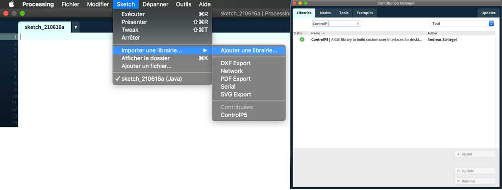
To create a nice interface easily and quickly there are libraries like for the Arduino IDE. There is a very nice library called ControlP5. This library written by Andreas Schlegel for the Processing programming environment. To add the ControlP5 library to Processing, just follow the add library process and search for ControlP5, then click install.
To install new library from menu, go to: Sketch -> Import Library… -> Add Library…
You are now ready to create your GUI application.
Once you have installed ControlP5, start with creating simple window. Follow the documentation below to get basic idea how to create window and add buttons to the window.
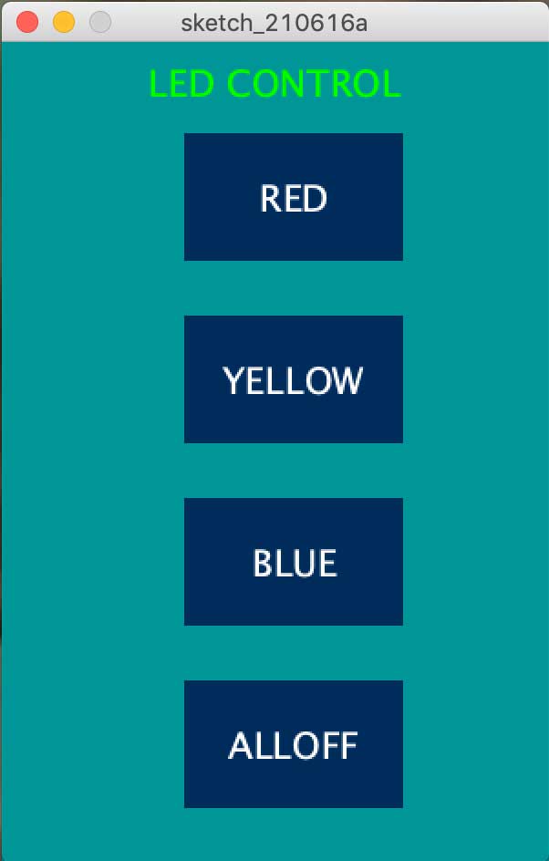
Here is the code that allowed me to create the interface.
import controlP5.*; //import ControlP5 library
import processing.serial.*;

Serial port;

ControlP5 cp5; //create ControlP5 object
PFont font;

void setup(){ //same as arduino program

  size(300, 450);    //window size, (width, height)

  printArray(Serial.list());   //prints all available serial ports

  port = new Serial(this, "/dev/cu.usbmodem14201", 9600);  //i have connected arduino to usbmodem14201 n my Mac

  //lets add buton to empty window

  cp5 = new ControlP5(this);
  font = createFont("PFont", 20);    // custom fonts for buttons and title

  cp5.addButton("red")     //"red" is the name of button
    .setPosition(100, 50)  //x and y coordinates of upper left corner of button
    .setSize(120, 70)      //(width, height)
    .setFont(font)
  ;

  cp5.addButton("yellow")     //"yellow" is the name of button
    .setPosition(100, 150)  //x and y coordinates of upper left corner of button
    .setSize(120, 70)      //(width, height)
    .setFont(font)
  ;

  cp5.addButton("blue")     //"blue" is the name of button
    .setPosition(100, 250)  //x and y coordinates of upper left corner of button
    .setSize(120, 70)      //(width, height)
    .setFont(font)
  ;

  cp5.addButton("alloff")     //"alloff" is the name of button
    .setPosition(100, 350)  //x and y coordinates of upper left corner of button
    .setSize(120, 70)      //(width, height)
    .setFont(font)
  ;
}

void draw(){  //same as loop in arduino

  background(0, 150 , 150); // background color of window (r, g, b) or (0 to 255)

  //lets give title to our window
  fill(0, 255, 0);               //text color (r, g, b)
  textFont(font);
  text("LED CONTROL", 80, 30);  // ("text", x coordinate, y coordinat)
}

//lets add some functions to our buttons
//so whe you press any button, it sends perticular char over serial port

void red(){
  port.write('r');
}

void yellow(){
  port.write('y');
}

void blue(){
  port.write('b');
}

void alloff(){
  port.write('f');
}
The code talks through a USB cable between my Mac and my board. It is therefore very important to know the exact name of the port on which your board is plugged. For me, it was plugged on the right USB port on my MacBook Pro, so its exact name is /dev/cu.usbmodem14201.
Check several times your communication port between your board and your computer
The rest of the code is that when a button is pressed then it sends a letter on the communication channel. The SAMD11C will receive this letter and will have to be coded to carry out an action according to the letter received.
Concerning the code on my board, it is very simple. When he receives a letter then he must perform an action. For example when it receives the letter “b” it is because the user has pressed the “blue” button so it turns on the blue LED which is connected to pin 8 of my SAMD. Same principle for the other functions. The cutoff function which is symbolized by the letter “f” makes sure to turn off all power supply on all the concerned pins of my microcontroller.
Here is the code to send to your board so that your microcontroller can control your LEDs according to the interface created.
int red = 14;
int yellow = 9;
int blue = 5;


void setup() {

  pinMode(blue, OUTPUT);   //set pin as output , blue led
  pinMode(red, OUTPUT);   //set pin as output , red led
  pinMode(yellow, OUTPUT);   //set pin as output , yellow led

  Serial.begin(9600);    //start serial communication @9600 bps
  }

void loop(){

  if(Serial.available()){  //id data is available to read

    char val = Serial.read();

    if(val == 'r'){       //if r received
      digitalWrite(red, HIGH); //turn on red led
      }
    if(val == 'b'){       //if b received
      digitalWrite(blue, HIGH); //turn on blue led
      }
    if(val == 'y'){       //if y received
      digitalWrite(yellow, HIGH); //turn on yellow led
      }
    if(val == 'f'){       //if f received
      digitalWrite(red, LOW); //turn off all led
      digitalWrite(yellow, LOW);
      digitalWrite(blue, LOW);
      }
    }
  }
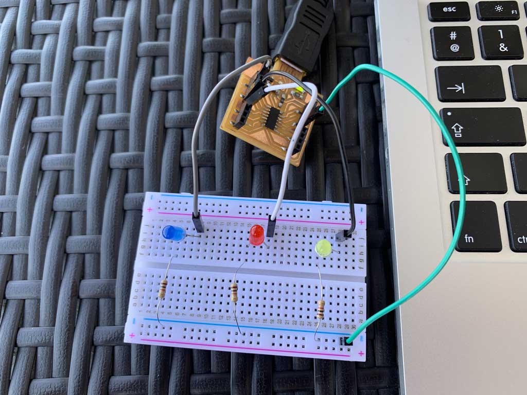
Material and connection
To realize this small assembly it is enough for you simply:
- A board with a microcontroller
- 4 wires
- 3 LEDS
- 3 resistors 100 ohm
- 1 breadboard
Then connect your LEDs to the pins of your microcontroller by positioning your resistors in the circuit. Connect each LED circuit to the ground and then use a wire to connect all your ground to the large board. Here is my connection.
When you have done all the steps before (making your interface, installing your code in your microcontroller, connecting your LEDs) you can launch your interface and start talking between your computer and your board.
Here is my final video
Group assignment
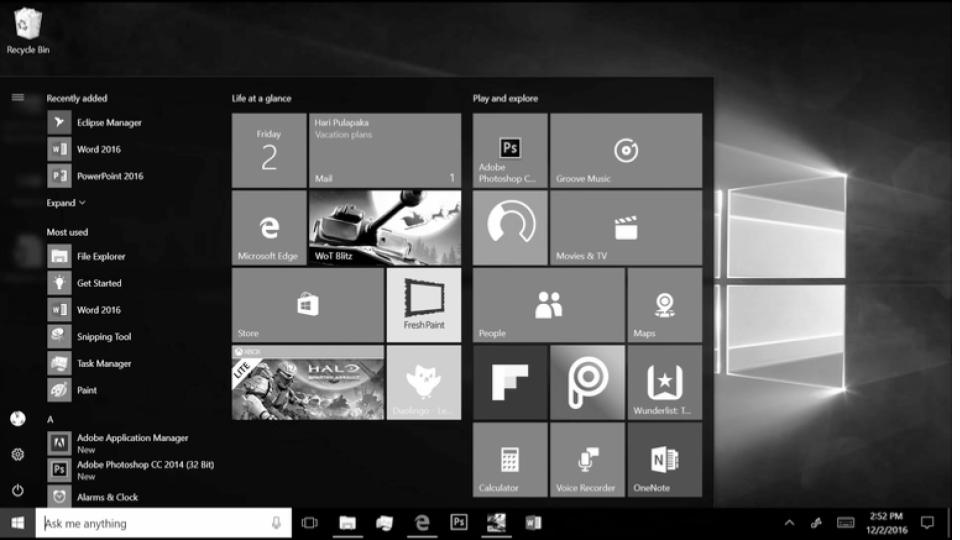
In the past Computers used to have simple text based interfaces.
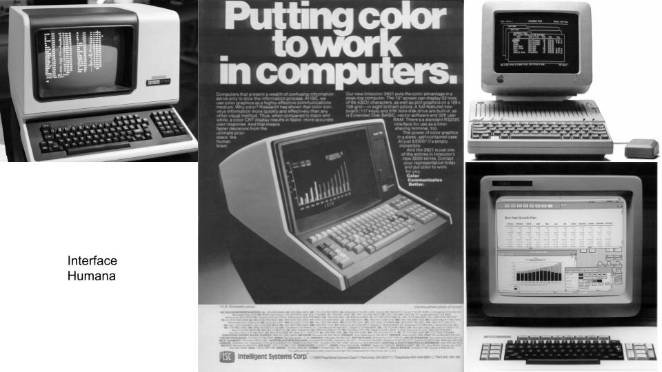
Over the years this changed to have visual more interactive interfaces.
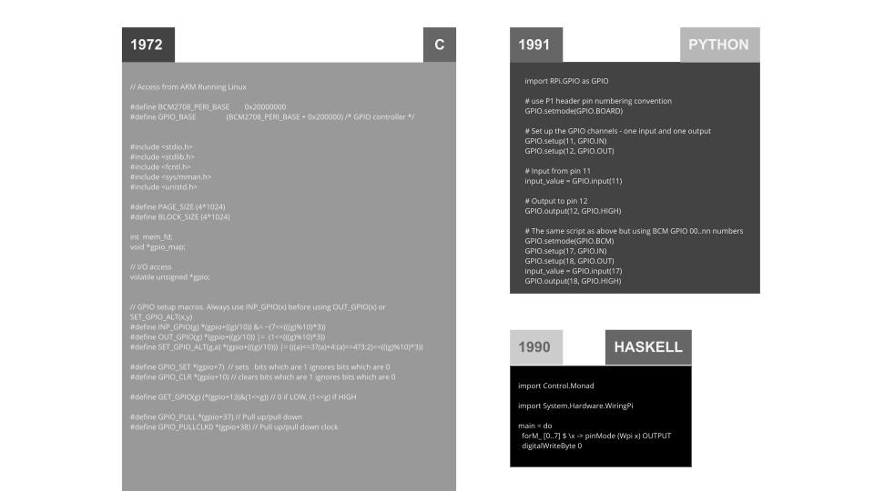
Language comparison:
| HTML method | Python programming | |
|---|---|---|
| Positive | Wireless connection. Can control a mechanism even from a distance. Works on computer, tablet or smartphone. Lots of documentation | Multiplatform and with Python integration to multiple programming paradigms |
| Negative | Need a wifi network to work. Loss connection regularly. Speed of action can sometimes be long. | Python is a interpreted language that doesn’t compiles itself except by using Nuitka or other code translators |