13. Output devices
This week was dedicated to the output, I could thus benefit from it to advance on my final project which is my robot follower of person. After having validated the ultrasonic sensor during the input week, I would like to focus on my motors during this week. Not having yet my final motors for the project I took some small test motors that we have at AgriLab. Following the steps of this week I will quickly approach the subject of the electric power, the transistors and the PWM pins of the SAMD11C.
Measure the power consumption of an output device

Document your work (in a group or individually)
• Individual assignment:
Add an output device to a microcontroller board you've designed and program it to do something
Hero shot
The motors used
For this week I will use small engines like this one:
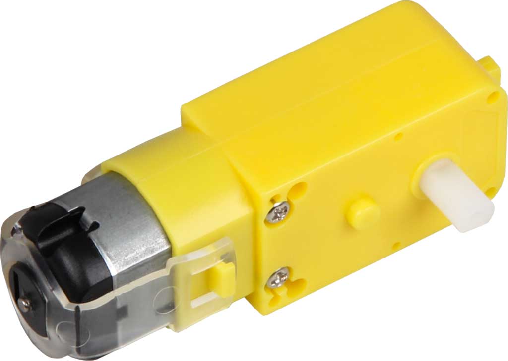
The interest of these motors is that they are small and very practical to use. Before making my robot I would like to make a small prototype. My goal for the next week is to make my small robot to check my code and the realization of this one before launching me in the construction of my final project. Moreover this prototype will allow me to visualize the defects to be corrected for my final project.
Datasheet engine :
| Datasheet | |
|---|---|
| Type | Gear motor with wheel |
| SHAFT | 3.6mm on both sides with a 1.9mm hole |
| ALIMENTATION | 3 - 9V DC |
| DIMENSION | 37,6 x 64,2 x 22,5 mm |
| WEIGHT | 58 g |
| Current in Idle (mA) | 190 |
| Rpm | 90 |
| Torque (gf/cm min.) | 800 |
H-bridge or transistor ?
The first question to ask when controlling motors is how they will work, will they only run in one direction or will they have to run in the opposite direction? For my future robot I don’t want it to go in reverse, so I don’t need to use an H-bridge. The H-bridge is composed of 4 transistors which, when opened, will direct the current in one direction or another, making the motor turn in one direction or another. For my project I will need only one transistor which with the excitation of my microcontroller will open or close to drive the motor.
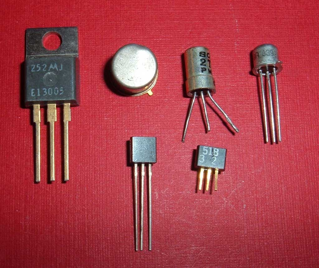
Why use a transistor?
The transistor is an electronic component that is used in most electronic circuits. A transistor is a semiconductor device with three active pins, which allows a current or voltage to be controlled at the output electrode (the collector in a bipolar transistor and the drain in a field effect transistor) by an input electrode (the base in a bipolar transistor and the gate in a field effect transistor).
With the circuit connected to the “drain” and “source” terminals, the transistor is insulating with no voltage on the “gate” terminal, and conducting with voltage on the Base terminal.
In other words, it is an electronically controlled switch with no mechanical parts.
 Credit : Wikipédia
How does it work?
A bipolar transistor has 3 pins: the gate, the source and the drain.
There are two types of bipolar transistors: NPN and PNP. We will only talk about NPN now.
A transistor is like a switch but electrical. So we can talk about ON and OFF. We know that a switch has only 2 legs (2 outputs). If it is ON, it lets the current pass and if it is OFF, the current does not pass. Well, these two legs of a switch are the same in a transistor. Indeed the drain and the source play this role.
Do we press an ON/OFF button too?
NO, since I mentioned the drain and the source, the gate is missing. It is the gate that will play the role of the button but electrically. That is to say if there is a voltage of about 0.7V between gate and source, we can say that the button is ON and the current passes between the source and the gate.
Electrical symbol of transistor
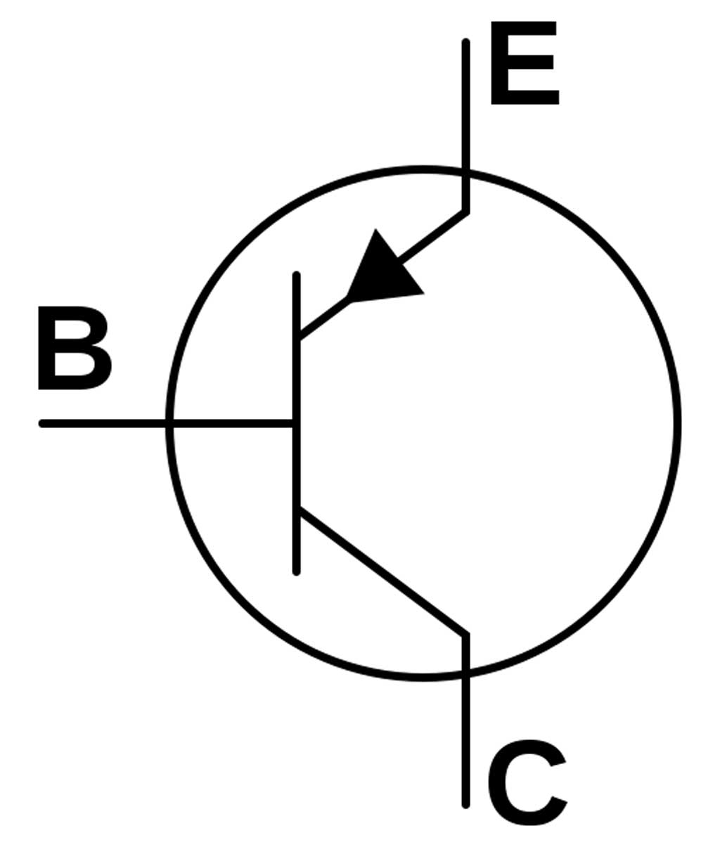
Now that we know what a transistor looks like and we know its electrical symbol, how do we make it work to turn on an output?
How to turn on a motor with a transistor?
First of all we have to activate the transistor, that is to say to put it in ON. To do this we connect a pin of our Arduino to the gate. The “drain” terminal of our transistor is connected to our motor terminal. The source terminal is connected to GND. It is better to add a diode and a capacitor to secure our transistor. With the power from the motor, when the transistor opens the motor, although not powered, continues to run. This generates an over-voltage across our transistor which could damage it. By adding a diode to the circuit, this will block the current and protect our electronic components. Finally, we code our Arduino so that it sends current to the terminals of our transistor, so that it closes and lets the current pass. You have understood the principle, if the transistor is ON the motor turns on.
Board made in week 10
Having already designed a board in week 10 I decided to use it again this week. As my board has several easily accessible inputs and outputs it was easy to use it for this week. Here is the link and the steps to build this board.
Making a board on KiCAD
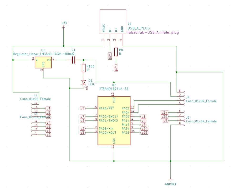
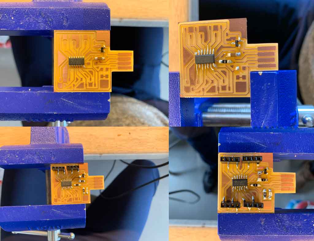
After having done all my tests with my modified board I decided to make another board with connectors directly on it. First I wanted to design a board with only 4 connectors for only my ultrasonic sensor. However, after thinking about it I decided to make a more versatile board and therefore decided to add several connection pins. For this I was inspired by the board of my instructor Florent. Having several fast connection slots allows me to have a versatile and easy to use board. Moreover I could reuse this board in the following weeks. It looks a bit like a small Arduino but with a SAMD11C inside.
Here is the electrical diagram of my board. This board has 16 connectors. 1 5V connector, 1 3,3V connector, 2 connectors for the GND and the rest for the microcontroller pins.
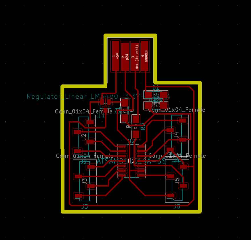
Here is the schematic of the traces of my board
To know how to add components in KiCAD and make this kind of board I invite you to watch my week 7 where I describe all the steps to design a board.
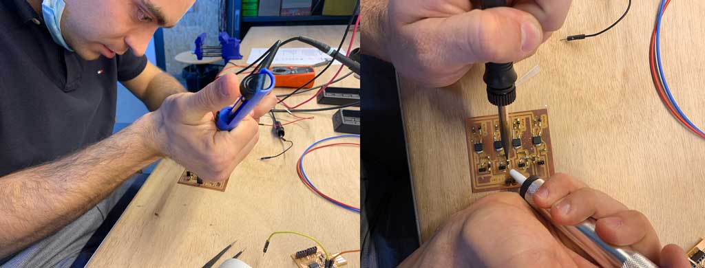
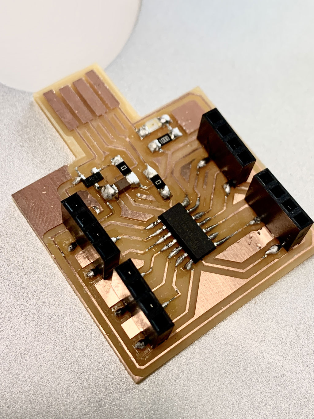
Soldering
After milling my copper plate I had to solder all the components on it. For that I needed :
- 1 SAMD11C microcontroller
- 1 transistor 3,3V 100mA
- 1 capacitor 1uF
- 2 resistors 0 ohm
- 1 resistor 100 ohm
- 1 LED
- 4 connectors HDR 4 position 0,1 TIN SMD
Flashing
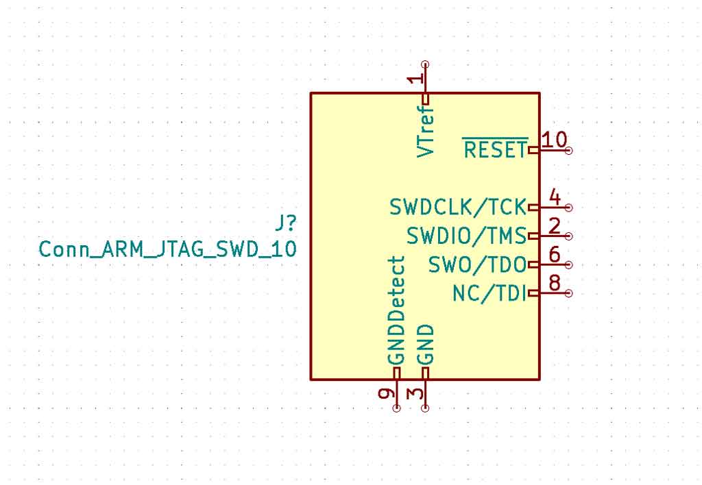
Not having a 10 pins connector to flash my board directly, I had to find another solution to program it. For that I used a custom cable. For this I used the symbol of the 10 pin connector on KiCAD. On the symbol you can see numbers next to it. On the wire there are also numbers, so I just plugged the right numbers on the right pins.
To flash a board you only need 5 wires :
- 1 wire for the power (number 1)
- 1 wire for the ground (number 9)
- 1 wire for the clock (number 4)
- 1 wire for the reset (number 10)
- 1 wire for the DIO (number 2)
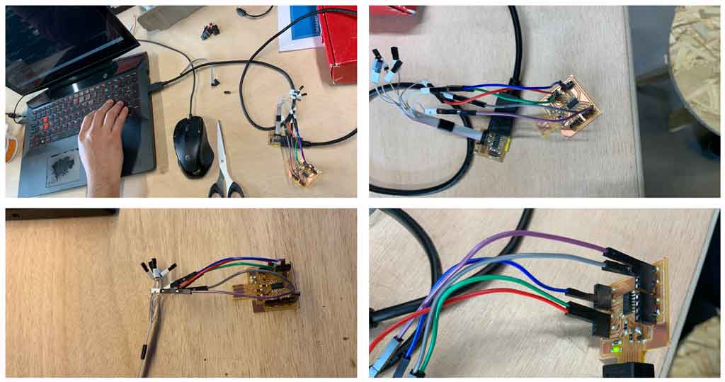
All numbers are placed on the connectors of the custom cable. You just have to connect the right numbers together.
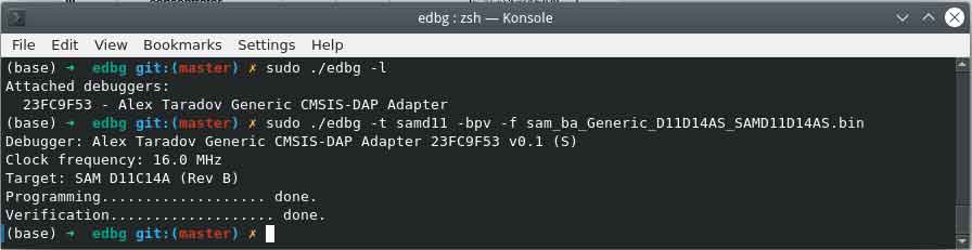
For the rest Antonio flashed my board because it was already ready and I just had to plug in my board.
Engine control board
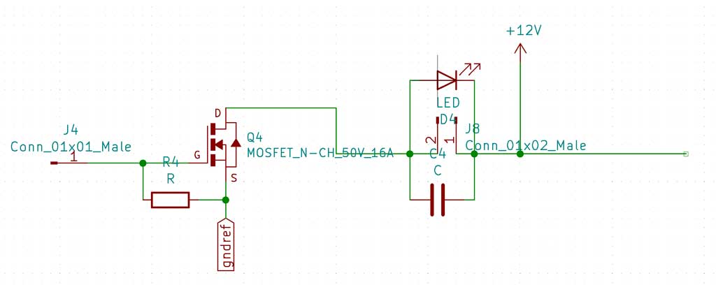
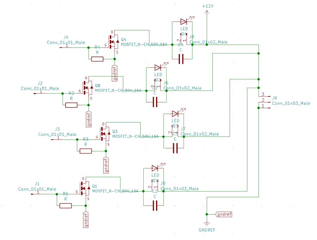
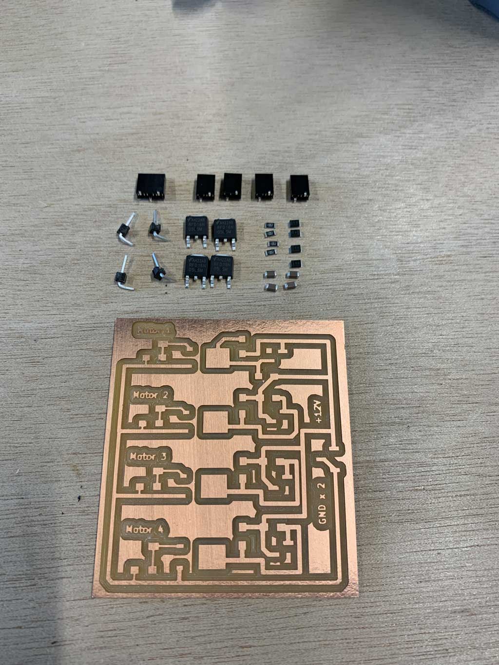
This week I decided to explore motors as an output. I want to start to see how an electric motor works and especially I would like to learn how to manage it. For this I looked at H-bridges but this is not interesting for me because I don’t want my robot to go in reverse. So I decided to build my own motor control board. For this I used high power transistors. The motors in my final project will require a lot of power, so I need transistors that can handle this electrical power. In the inventory I saw that we have transistors able to accept 50V and 16A, so those are the ones I decide to take. For this week, as I don’t have my motors yet, I’m going to try on smaller motors. I know that these transistors are oversized for my use this week but I would like to reuse this board for my final project.Wishing to have a 4 wheel drive cart with 4 independent wheels I decided to put 4 power circuits on my board. So I made the same wiring diagram 4 times to connect my 4 motors. Here is the whole wiring diagram made on KiCAD:
Then I generated the list of components that I imported in the PCB to make my traces and the external cut.
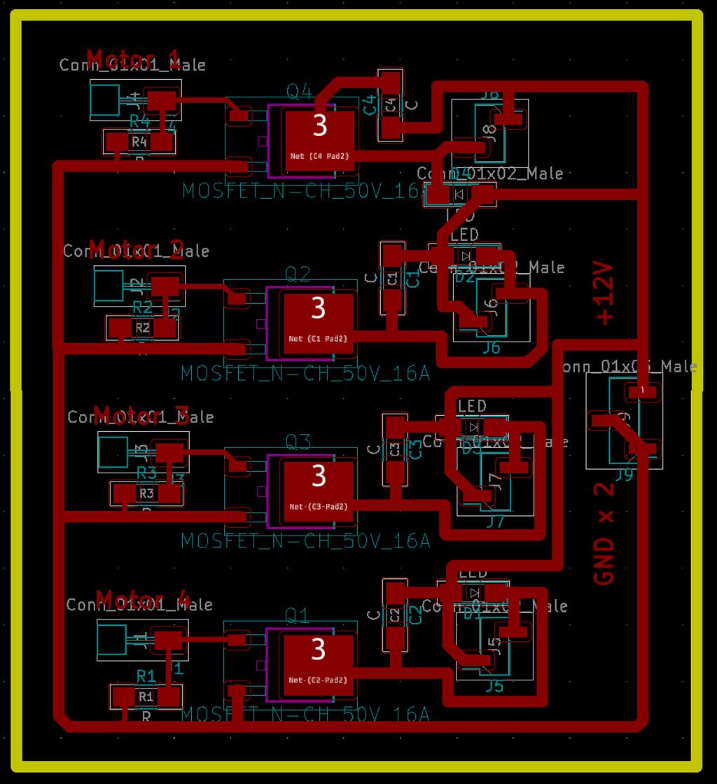
Some tracks are wider than others because these tracks will transmit a lot of electrons. To avoid any risk of overheating on my board it is better to machine wider tracks
PS: to remind you how to make these steps before I invite you to review my week 8 by clicking here.
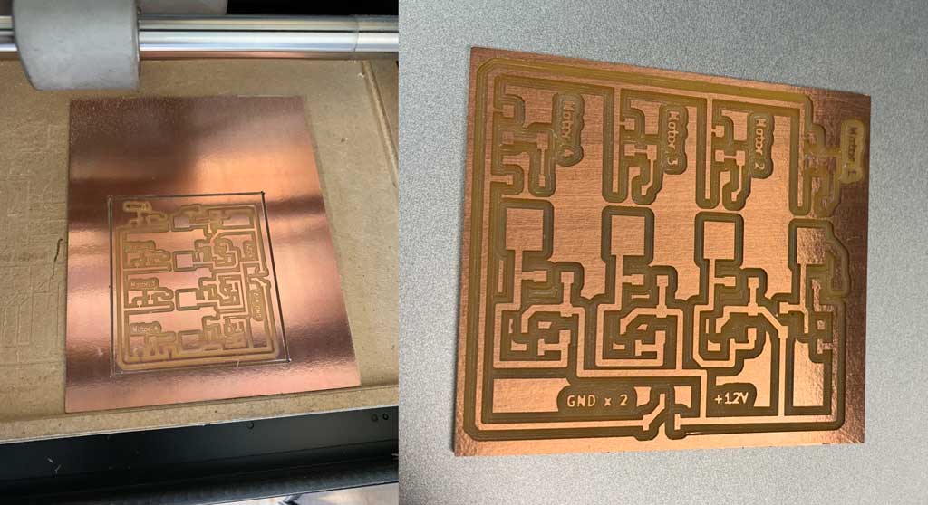
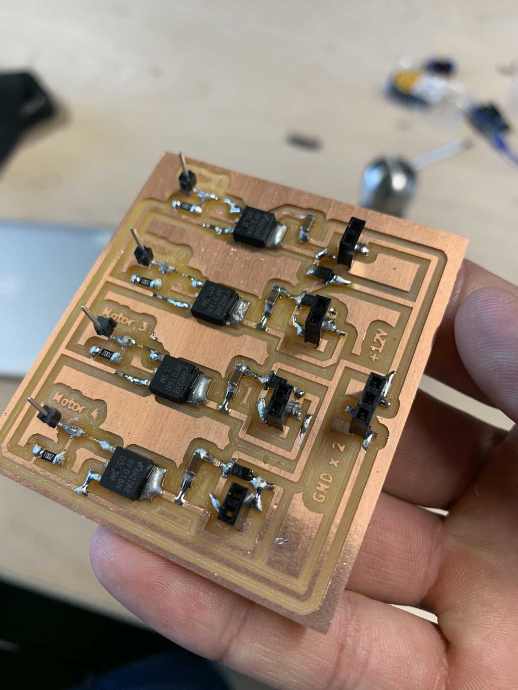
Soldering
Once I had machined my board I soldered my components on the board. For this I used :
- 4 male connectors
- 4 x 10k Ohm resistors
- 4 transistors 50V and 16A
- 4 capacitors 1 uF
- 4 schottky diodes 100V 1A
- 4 female connectors 2 x 1
- 1 female connector 3 x 1
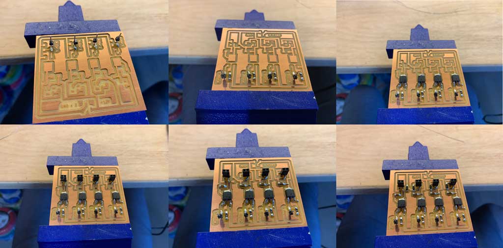
I then soldered my components by going from left to right all the lines at the same time. This allows me to see quickly if I forgot some components.
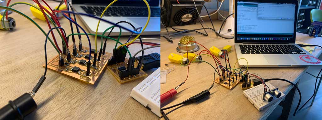
Input
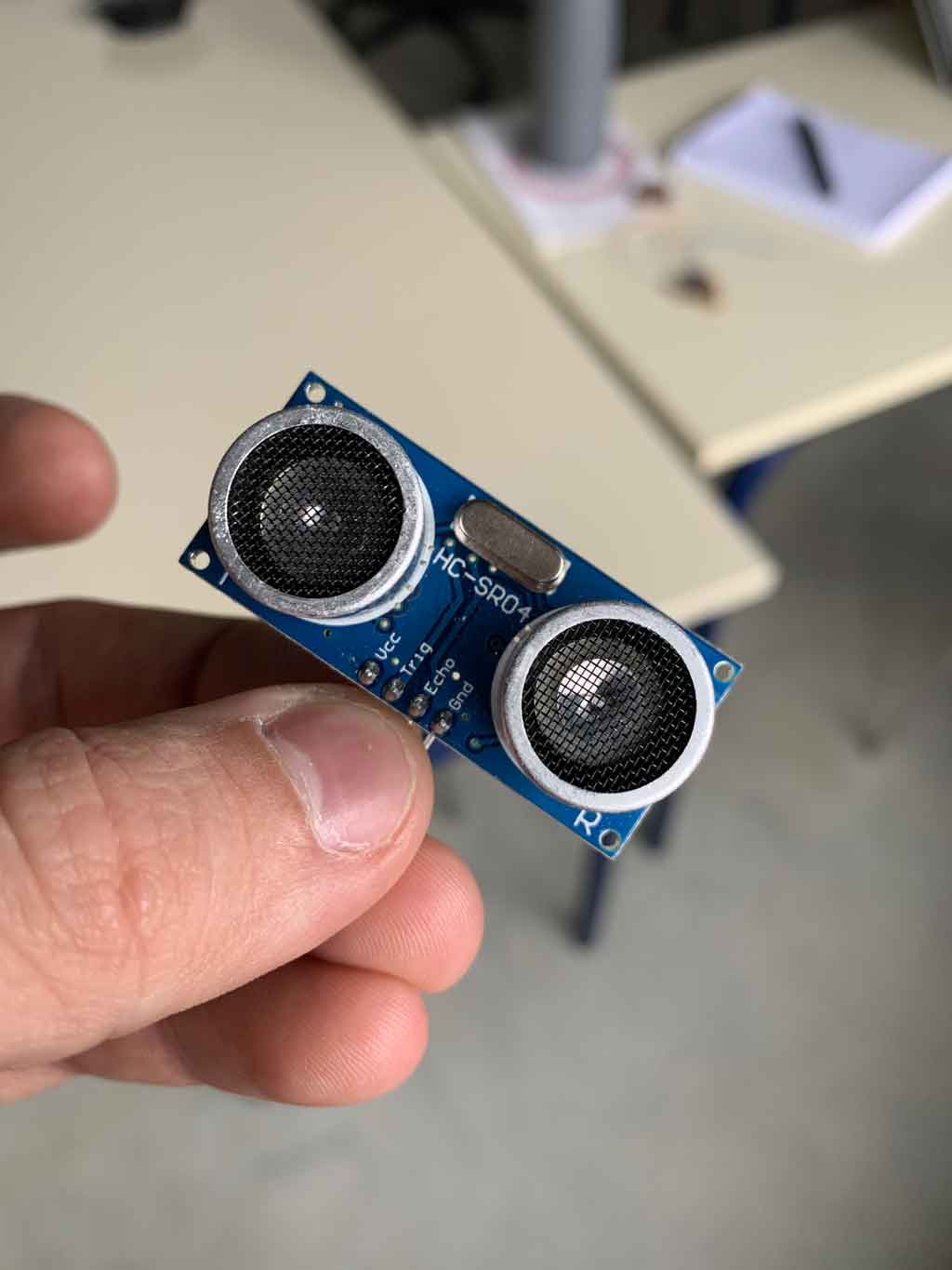
Wishing to integrate the ultrasonic sensor in my final project and having performed several tests with it during the input week, it seemed logical to me to reuse this sensor as an input. So I used the HC-SR04 ultrasonic sensor. The utility of this sensor is more a security, it will have to interrupt any activity of my robot if this one approaches an object. For that I reused the part of code which I had used during my week 10 that I slightly modified to make it correspond to my expectations of this week.
Wiring
My goal for this week was to regulate the speed of the motors depending on the distance you are standing. For that I used the PWM (Pulse Width Modulation) pins of my SAMD11C.
PWM pins are pins that modulate their pulse frequency and therefore modulate the speed or current of the output component. In my case I want the speed of my motors to accelerate when I move away and decrease when I get closer to the ultrasonic sensor until it stops if I am too close. To do this, the number of pulses must be adjusted. The closer the pulses are to each other, the faster the motor will run. If, on the other hand, we make micro-pauses between each impulse, the motor will turn at a lower speed. This is not visible to the naked eye, but the motor stops and runs very quickly, which is how the motor speed is reduced.
The PWM pins of the SAMD11C that I will use for the following are pins 1,4,5 and 14. I will connect my ultrasonic sensor to the digital pins 2 and 3 of my SAMD11C.
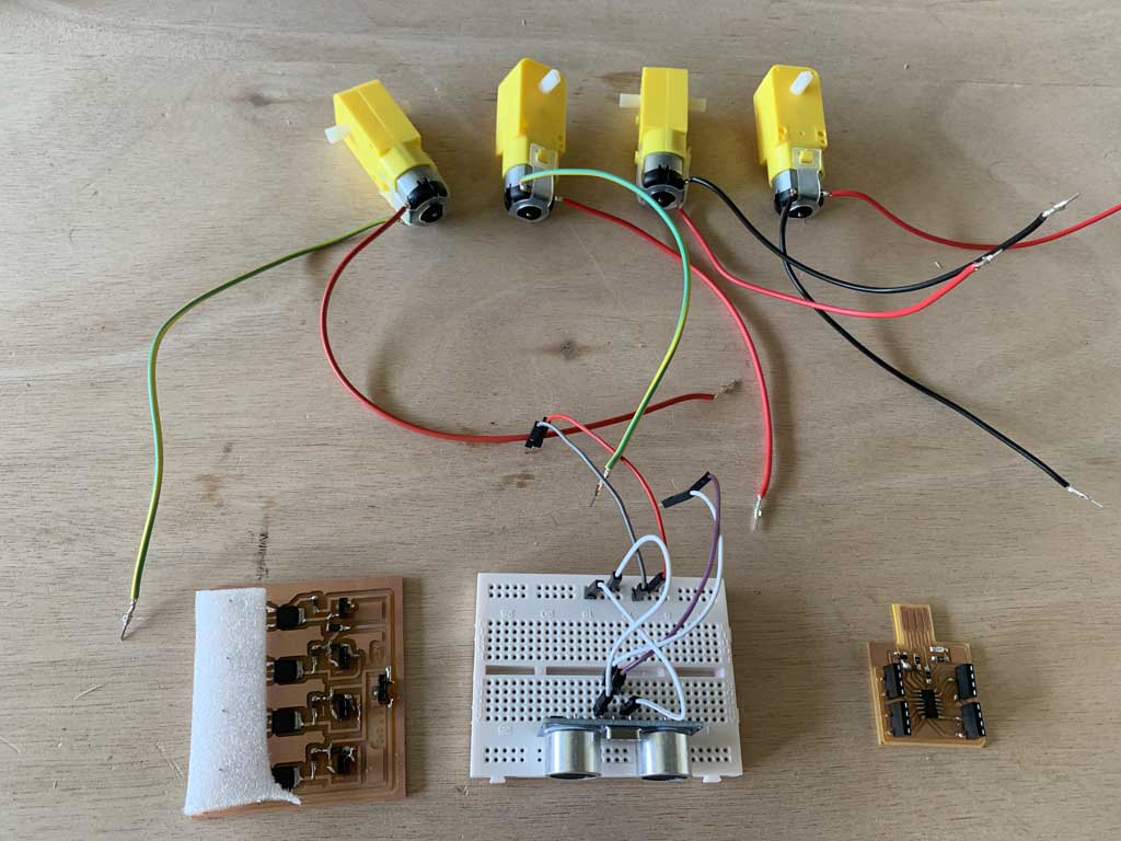
To carry out this exercise I will use :
- 4 motors described above
- My board made in week 10
- My board made this week to control the motors
- An ultrasonic sensor HC-SR04
- A breadboard
- Connection wires
The code
//moteurs

int M1 = 5;  //Moteur 1
int M2 = 14;  //Moteur 2
int M3 = 15;  //Moteur 3
int M4 = 4;  //Moteur 4

// Ultrason

int TRIG = 8; //borne trigger de l'ultrason
int ECHO = 9; //borne echo de l'ultrason
long lecture_echo;
long cm;


void setup()
{
 Serial.begin(115200); //nombre de baud pour le moniteur série

pinMode (M1, OUTPUT); //déclare que M1 est une sortie
pinMode (M2, OUTPUT); //déclare que M2 est une sortie
pinMode (M3, OUTPUT); //déclare que M3 est une sortie
pinMode (M4, OUTPUT); //déclare que M4 est une sortie
pinMode (TRIG, OUTPUT);//Emetteur ultrasons
digitalWrite(TRIG, LOW);
pinMode (ECHO, INPUT); //Récepteur ultrasons

}

void go()
{

analogWrite (M1, 240); //Fait tourner le moteur à 95% de sa vitesse
analogWrite (M2, 240); //Fait tourner le moteur à 95% de sa vitesse
analogWrite (M3, 240); //Fait tourner le moteur à 95% de sa vitesse
analogWrite (M4, 240); //Fait tourner le moteur à 95% de sa vitesse

}

void stop()
{

analogWrite (M1, 0); //Fait tourner le moteur à 0% de sa vitesse
analogWrite (M2, 0); //Fait tourner le moteur à 0% de sa vitesse
analogWrite (M3, 0); //Fait tourner le moteur à 0% de sa vitesse
analogWrite (M4, 0); //Fait tourner le moteur à 0% de sa vitesse

}

void slow()
{

analogWrite (M1, 100); //Fait tourner le moteur à 40% de sa vitesse
analogWrite (M2, 100); //Fait tourner le moteur à 40% de sa vitesse
analogWrite (M3, 100); //Fait tourner le moteur à 40% de sa vitesse
analogWrite (M4, 100); //Fait tourner le moteur à 40% de sa vitesse

}

void loop()

{

digitalWrite(TRIG, HIGH);
  delayMicroseconds(10);
  digitalWrite(TRIG, LOW);
  lecture_echo = pulseIn(ECHO, HIGH);
  cm = lecture_echo /58;
  Serial.print("Distance en cm :");
  Serial.println(cm);


if (cm <= 30)
{
  Serial.println("Arret d'urgence");
   stop();
}

else if (cm <= 50)
{ // 50 >= cm > 30
  Serial.println("Tranquillement");
   slow();
}

else // cm > 50
{
  Serial.println("Go !");
   go();

}
}
To start I initialized all my used pins, my 4 pins for the motors and my 2 pins for my ultrasonic sensor. I then declared my pins that were in and out. Then I created 3 different functions that will be called later in the code.
- One function where the 4 motors go at 95% of their speed
- Another one where the motors go at 40% of their speed
- A function that stops the motors completely.
How to play on the speed of the motors thanks to the code?
To do this, use the “analogWrite” function. After a call to analogWrite(), the pin will generate a steady square wave of the specified duty cycle. the duty cycle: between 0 (always off) and 255 (always on). Allowed data types: int.
We then enter the code loop. The first block is for measuring the distance between the sensor and an object in front of it. This block is a copy/paste from my input week and is explained in detail during this week.
The rest of the code means that “if” the distance is less than 30cm then the “stop” function should be called which stops the motors. However, if the distance is between 30 and 50cm then call the “slow” function which makes the motors move forward slowly. And finally if the distance is not greater than 50cm then call the “go” function which makes the motors go quickly. The “serial.println” commands are used to write the current command to the monitor.
Hero video
Because pictures are better than words here is my final video of the week
Conclusion
This week was very satisfying for me, I was able to start visualizing more specifically how my robot would work. I plan to reuse the knowledge I have gained over the last few weeks and add a camera with a communication port to control my motors and therefore my robot. However I’m starting to be limited in capacity in my SAMD11C, so I will change microcontroller next week to have more memory. I would like to stay in the SAMD environment that I have used many times but my first idea is to switch to a SAMD21E.
Mistakes
When I soldered my diodes, although I was aware of the polarity, I reversed the direction. So I had to unsolder all my diodes to make them rotate 180°, without that my whole circuit didn’t work.
Conclusion: be very careful with the direction of your diodes!