15. Networking and communications
The goal of this week was to give us a look at the working principle of the communication between two microcontrollers. In the rest of this documentation I will detail the I2C communication between two Arduinos (students) and my board that I created a few weeks ago (SAMD11C, teacher).
-
Send a message between two projects
-
Individual assignment:
Design, build, and connect wired or wireless node(s) with network or bus addresses
Vidéo shot
I2C
The I²C bus (Inter Integrated Circuit) is a serial bus: 3 wires to get everything through. It was developed in the early 1980s by Philips to minimise the connections between the digital integrated circuits of its products (TVs, HiFi elements, VCRs, etc.).
Today, Philips has in its catalogue more than 150 CMOS and bipolar ICs that are I²C compatible. Other manufacturers have also developed ICs that can be connected to the I²C bus. The protocol used is simple and fast.

The I²C bus allows a wide range of electronic components to communicate with each other using only three wires: a data signal (SDA), a clock signal (SCL), and an electrical reference signal (ground).
The bus monitoring
In order to transmit data on the I²C bus, two particular conditions must be monitored: the start condition and the stop condition.
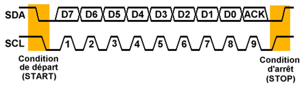
Before attempting to take control of the bus, a circuit must check that the SDA and SCL lines are idle, i.e. in the high state. If this is the case, the circuit indicates that it is taking control of the bus by setting the SDA line to 0. From this point on, other circuits know that the bus is busy and should not attempt to take control of it. The circuit that has just taken control of the bus becomes the master. It generates the clock signal, regardless of the direction of the transfer.
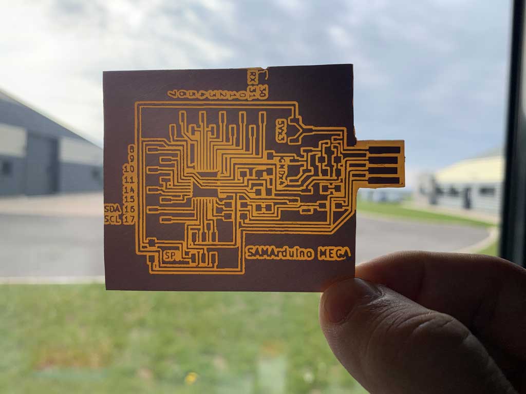
Kicad Design
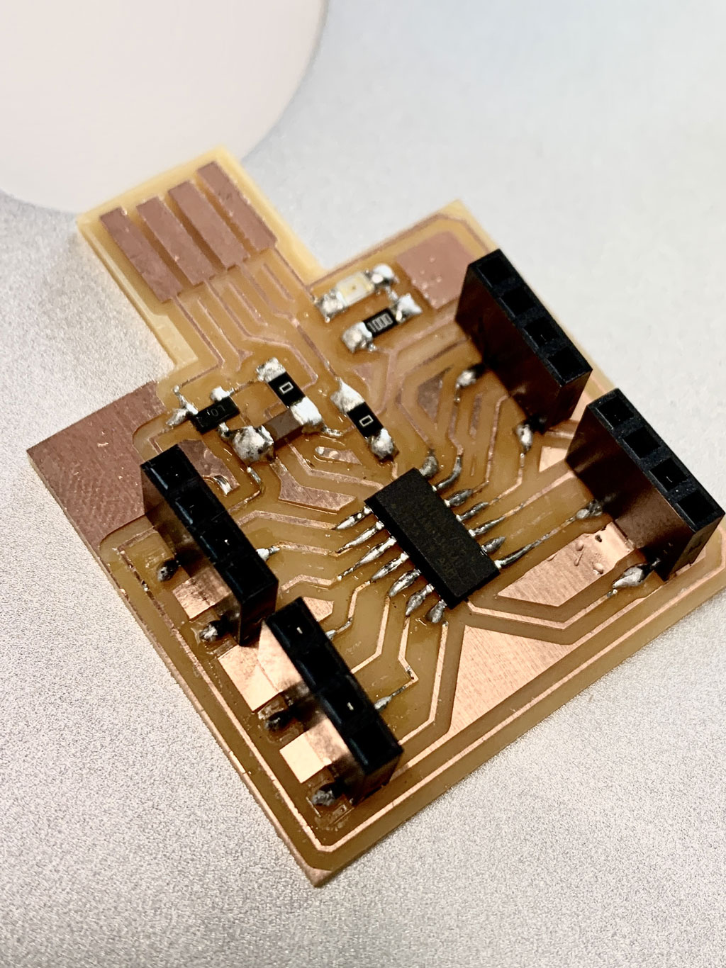
I reused my board that I created during the input week, everything about how I designed it is explained in more detail during the Input week.
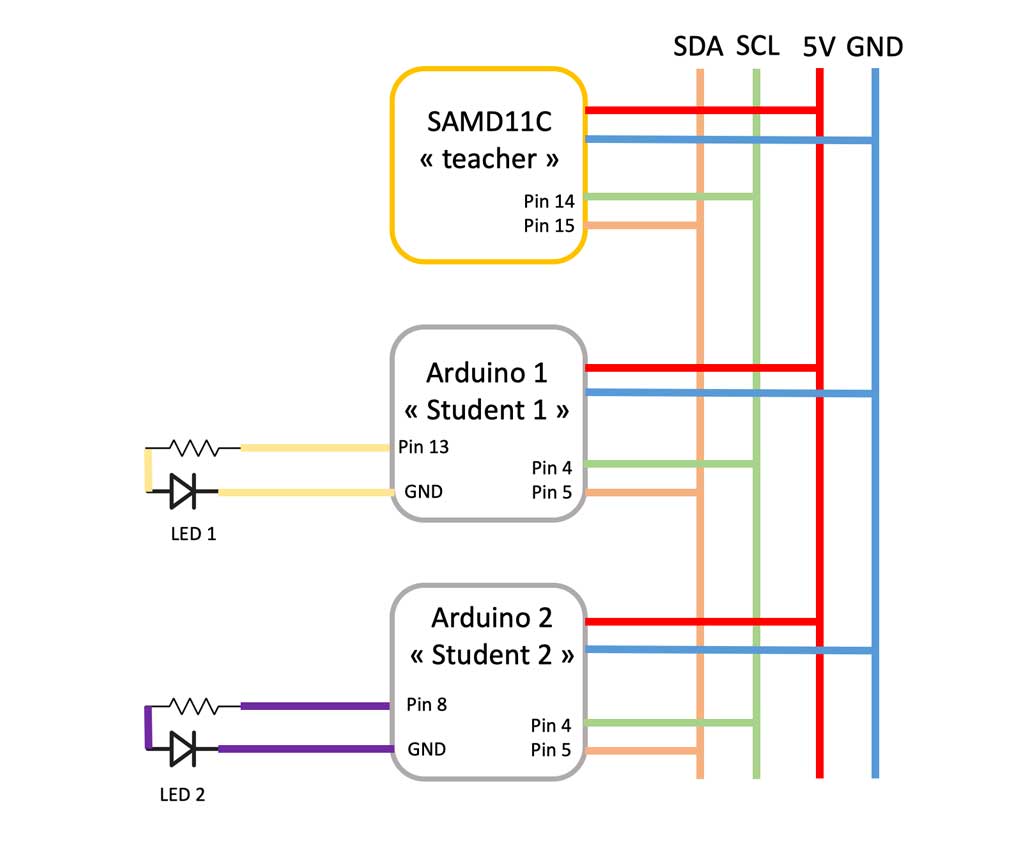
Principle of the assembly
The assembly will be divided into 2 parts:
The power supply part :
-
The “student” Arduinos : They will have an LED and its resistor wired between its digital 13 output and GND for student 1 and on pin 8 for student 2. Student 1 will use its 5V output and GND to power the second student Arduino.
-
The SAMD11C “teacher” : My board gets its power supply by being connected to my Mac.
The communication part :
To establish the connection between these 2 Arduinos and my board, it will be necessary to connect the SDA/SCL signals:
- Analog terminal 4 (SDA) of the “student” Arduinos to connect with pin 14 of the “teacher” SAMD11C.
- Analog terminal 5 (SCL) of the “student” Arduinos to connect with pin 15 of the “teacher” SAMD11C.
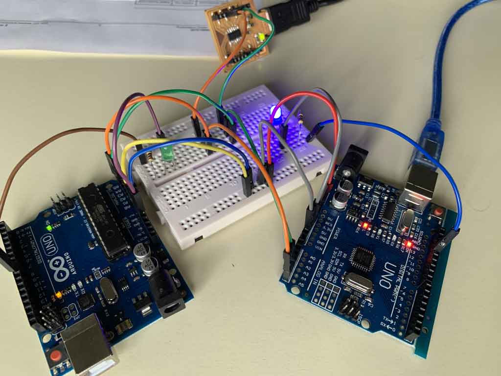
Assembly drawing
The code
The Wire.h library allows to simply define the serial communication on the I2C bus. This library allows you to communicate with I2C / TWI devices. On the Arduino boards with the R3 layout (1.0 pinout), the SDA (data line) and SCL (clock line) are on the pin headers close to the AREF pin. The management of the I²C bus and the TWI (Two Wire Interface) hardware functions of Atmel processors is natively integrated in the Arduino IDE and therefore does not require the installation of external libraries.
As a reference the table below shows where TWI pins are located on various Arduino boards and SAMD11C
| Board | I2C/TWI pins |
|---|---|
| Uno | A4 (SDA), A5 (SCL) |
| Mega2560 | 20 (SDA), 21 (SCL) |
| Leonardo | 2 (SDA), 3 (SCL) |
| Due | 20 (SDA), 21 (SCL) |
| SAMD11C | 14 (SDA), 15 (SCL) |
Wire.begin() allows to initialize the device address. The argument of the function can be empty for master devices.
Wire.write() allows to send bytes.
Wire.requestFrom() manages the request reception function.
Wire.beginTransmission() starts the data transmission and defines the receiver.
Wire.endTransmission ends the data transmission.
Wire.onRequest() manages the request reception function.
Wire.onRecieve() handles the receive data function.
Student code :
#include <Wire.h> // Library for communication I2C

const int L1 = 13; // Pin 13 = L1 (LED 1)

void setup()
{
Wire.begin(1); // Connection to bus address n ° 1 (you can put any number you want), this is the address
Wire.onReceive(receiveEvent); // Specific function for data reception
Serial.begin(9600); // Start the serial communication with the PC
pinMode(L1, OUTPUT); // L1 is a output
}

void loop()
{
delay(100);
}

// Function that executes if something is present on the interface
void receiveEvent(int howMany)
{
int x = Wire.read(); // Receive a number
Serial.println(x); // Display this number on the serial interface
if(x == 1)
{
digitalWrite(L1, HIGH); // Turn on L1
}
if(x == 0)
{
digitalWrite(L1, LOW); // Turn off L1
}
}
Teacher code :
#include <Wire.h> // Library for communication I2C

void setup()
{
Wire.begin(); // Join the I2C bus (No address needed for the teacher).
}

void loop()
{
//contenu du programme
Wire.beginTransmission(1); // Send to device #1
Wire.write(1); // Send 1
Wire.endTransmission(); // Stop transmission
delay(1000); // Wait 1s
Wire.beginTransmission(1); // Send to device #1
Wire.write(0); // Send 0
Wire.endTransmission(); // Stop transmission
delay(2000); // Wait 2s

Wire.beginTransmission(2); // Send to device #2
Wire.write(1); // Send 1
Wire.endTransmission(); // Stop transmission
delay(1000); // Wait 1s
Wire.beginTransmission(2); // Send to device #2
Wire.write(0); // Send 0
Wire.endTransmission(); // Stop transmission
delay(2000); // Wait 2s
}
Hero Video
Conclusion
This week was very useful, the fact of being able to communicate between two boards by the Tx/Rx voice during the group assignment was very nice. For the future I would like to use a Pixycam2 for my final project using I2C voice. I will use this week’s knowledge to realize the communication between my camera and my microcontroller.
Mistake
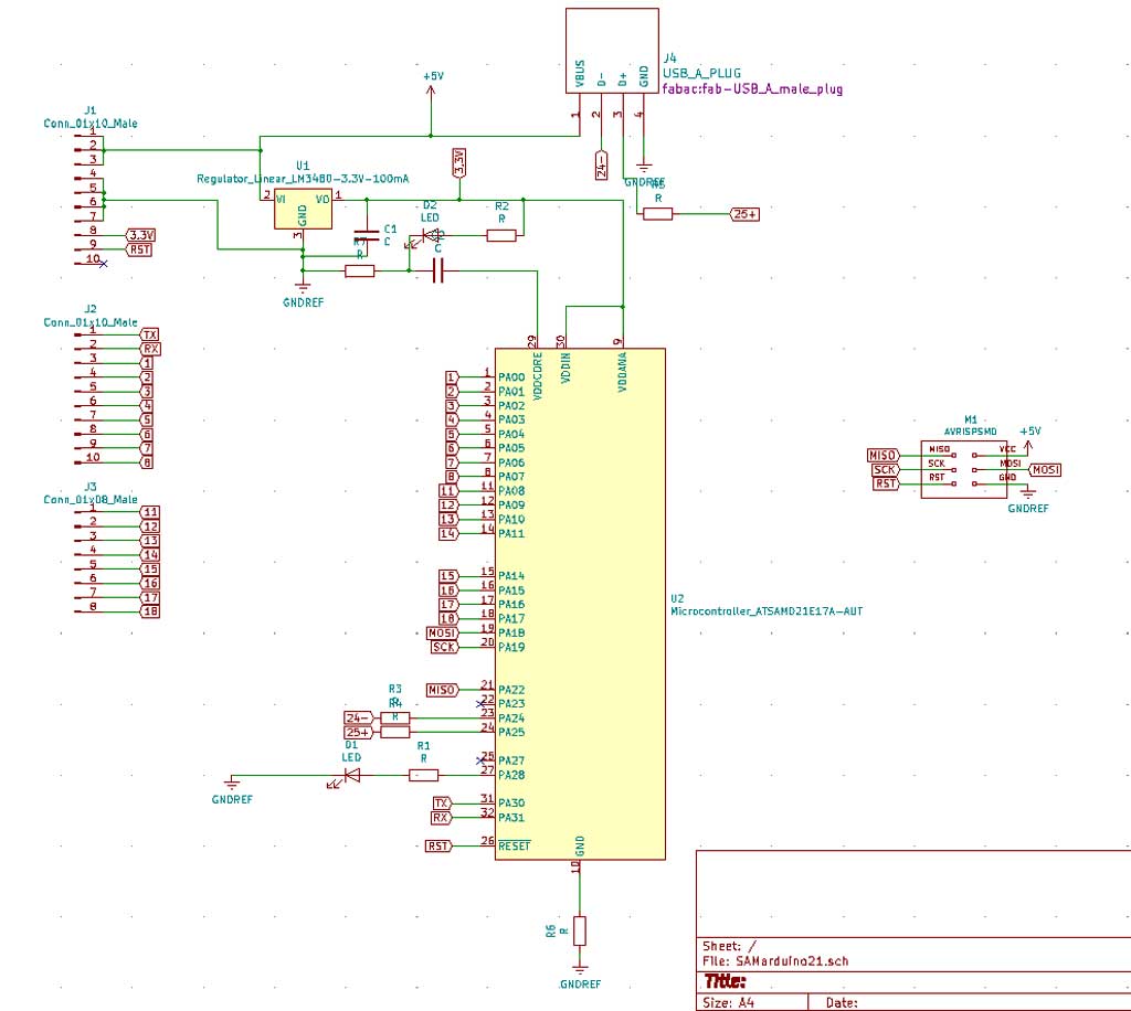
For this week I wanted to create a board by changing the microcontroller. I wanted to use the SAMD21E. The advantage of this microcontroller compared to the SAMD11C is that it has more pins and especially more memory. It is essential for me and for my final project to have this kind of microcontroller. So I took advantage of this week to make this board.
Here is the electrical diagram made on Kicad. As you can see there are many output pins easily accessible and a SPI socket to be able to communicate easily with all types of input. So this board is very versatile and suited my needs very well.
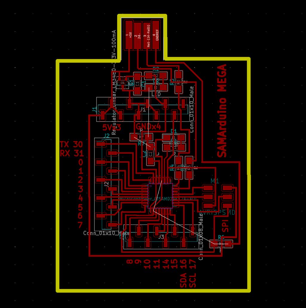
The trace design on PCBNews.
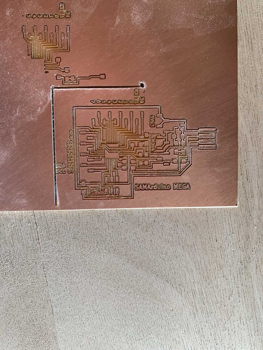
The milling process
The first step of the machining went very well, my traces are perfect. I then inserted the 1mm drill bit to make the outer cut.
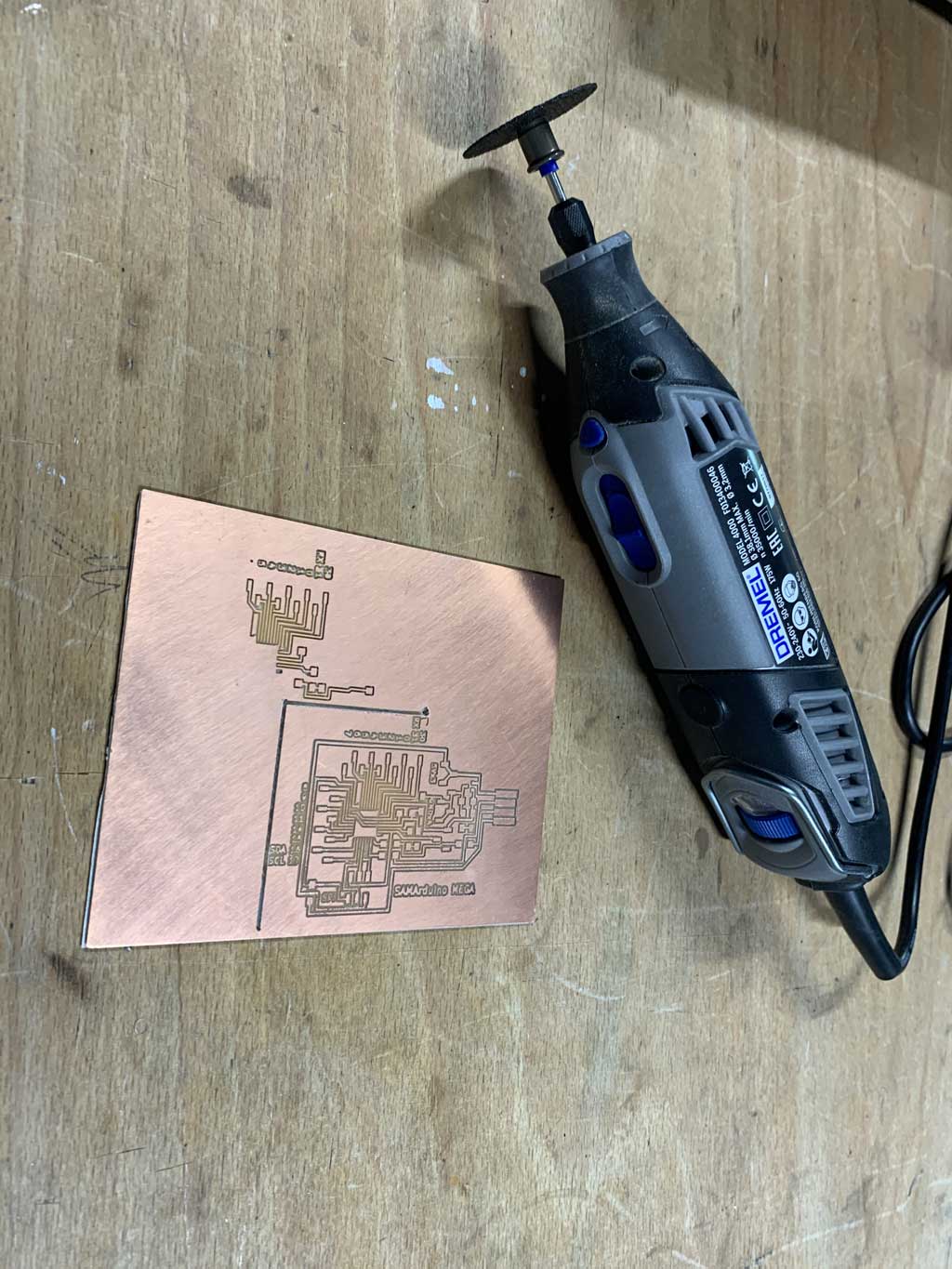
Error within an error
During the external cutting process my plate came off the sacrificial layer. With a lot of luck I was close enough to stop the machine quickly without it creating too much damage.
I was not the only one to use the machine I left the machine to my friends to do their assignment. As the machine had not damaged my tracks I decided to do the external cutting with the Dremel. By doing this, I was able to use my board and solder it.
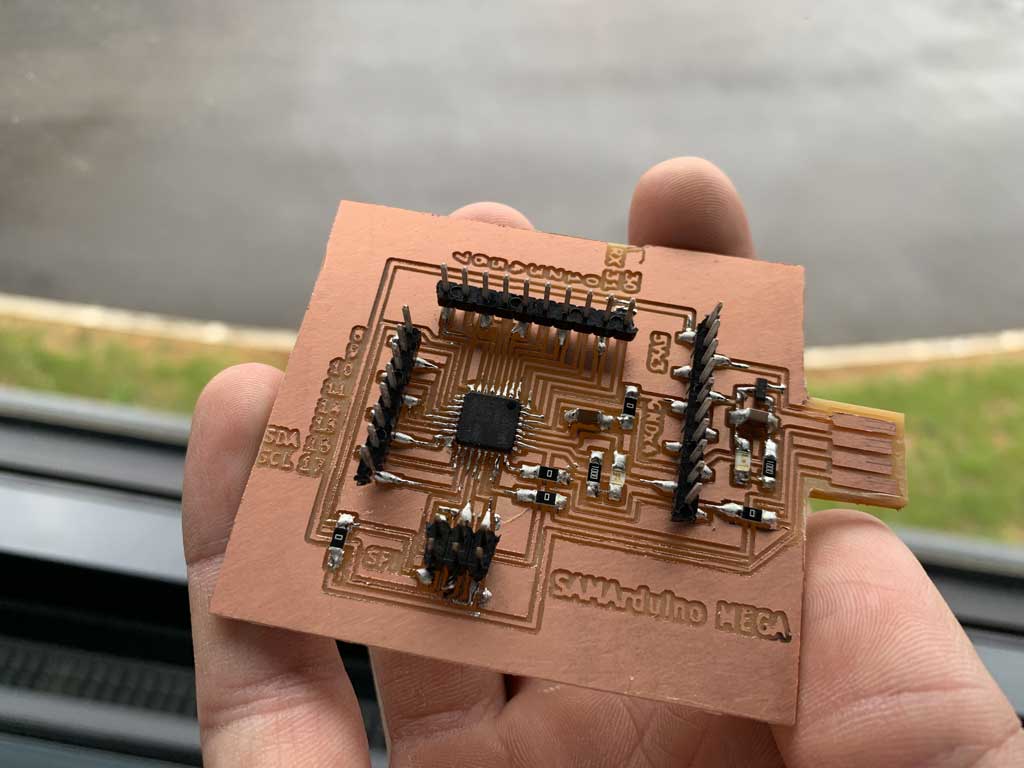
Soldering
Flash
I then flash the microcontroller with the bootloader for the SAMD21E found here
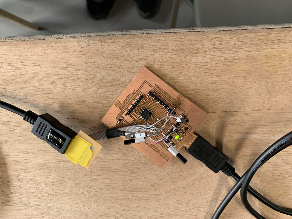
The problem in all this is that I succeeded in flashing with the Arduino application a blink but now the board is not recognized on any PC. For the rest of the week I have done all the work with my board created during the input week.