4. Computer controlled cutting
This week which was dedicated to computer controlled cutting we used machines such as a vinylcutter or a lasercutter.
Assignment
Group assignment : Characterize your lasercutter’s focus, power, speed, rate, kerf, joint clearance and types.
Individual assignment : Cut something on the vinylcutter. Design, lasercut, and document a parametric construction kit. accounting for the lasercutter kerf, which can be assembled in multiple ways, and for extra credit include elements that aren’t flat.
Hero shot

Vinylcutter
At AgriLab we have the CAMEO vinyl cutter. The software that works with this type of machine is Silhouette studio.
 Vinyl machine, Silhouette CAMEO 3
A few quick words about our vinylcutter :
It connects to PC or Mac with a simple USB cable. The Silhouette Cameo 3 uses a small blade to cut more than 100 different materials including paper, cardboard, vinyl and fabric up to 30 cm wide and 3 m long. When you replace the blade with a pen, the Cameo can also draw and make dotted lines.
The Silhouette Cameo 3 has a double trolley. You can insert your tools (an AutoBlade blade and a Silhouette pen) into the corresponding tool holders that you have assigned in your cutting parameters in Silhouette Studio. Your machine performs two different functions in succession for a single cutting job. The use of the left-hand tool holder allows automatic adjustment of the blade length, the Cameo 3 is the only machine compatible with this AutoBlade system.
 Double trolley of Silhouette CAMEO 3
The Cameo 3 has a higher training bar (2 mm) than previous Cameos. This allows you to load and cut thicker materials (provided the material is compatible) using the deep cutting blade.
Here is what I have done with the vinyl cutter:
| Steps | Comments | Illustrations |
|---|---|---|
| 1 | Choose an image. For my part, I decided to take the logo I made 2 years ago for the BDE election of my school. |  |
| 2 | Import it to Silhouette studio. My logo was in .png, so I had to vectorize it to allow the machine to make its way. |  |
| 3 | Vectorize the image. A quick vectorisation tool is already available on studio silhouette. Open this tool and select the part you wish to vectorize. Fine-tune the settings so that your image is well vectorized. Once your image is all yellow you can save it. Then you can increase or decrease its size, change its position… |  |
| 4 | Load the machine. Take a roll of the colour you want. Always position the vinyl part at the top and the support at the bottom. Position the roller and the ribbon straight in front of the machine’s drive rollers. A small symbol is present on the machine to guide you (a white bar with two arrows). The old cutting line must be straight (if it is not the case you have to cut it again to make it straight). Press load when everything is ready. |  |
| 5 | Send the image to the machine. When your image is vectorised and ready for cutting you can click on send. Adjust the machine settings (force, speed, number of passes…) and start cutting. |  |
| 6 | Cut out your design and weeding the parts you didn’t want. |  |
| 7 | Application of the transfer adhesive. Once the unwanted parts have been removed, position the transfer adhesive on your drawing and press firmly on the film so that both parts stick well together. Remove the transferred film with your project. |   |
| 8 | Position it on an object of your choice, for me my computer. |  |
How do you set up your machine ?
Before starting cutting, you need to understand the principle and operation of the machine. The cutting machine follows a path that has been recorded on the silhouette software. You can insert felts or a blade to cut the material.
The interest is to cut the vinyl without damaging the support. To do this, you have to adjust the strength of the blade according to the vinyl used. If the force is too weak, then the blade will not cut the vinyl and if it is too strong the blade will cut the vinyl but also the support. Speed plays an important role in the cutting process, so it is important that the blade is not too fast, otherwise the vinyl will be torn off without being cut. If you set your machine to a low speed, it is not disturbing at the moment but you risk losing a little more time.
For this exercise the settings were as follows : Speed : 5 and Strength : 10
Laser cutting
The machine :
Chinese Laser Cutter CO2 model painted and rebranded under MlLaser name. It’s a 150 Watt CO2 Tube.

Before going into the details of what the machine is made up of, I would like to come back to a few important points.
Laser cutting is a manufacturing process in which material is cut using a large amount of energy generated by a laser and concentrated on a very small area. By focusing a laser beam, the temperature of a small area of material can be raised until it vaporises. The power of a laser varies according to the material to be cut and its thickness. This process allows a precise, clean and fast cutting of many materials.
The machine emits a large amount of energy, which generates a significant heat source. The machine may catch fire, so it is mandatory to stay in front of the machine when it is in use. The smoke emitted from the machine may be toxic, so it is important to check the properties of its materials before using it in the machine.
What the laser machine consists of :
- A CO2 laser tube, when an electric current passes through it, emits a specific light.
- A cooling system, to lower the temperature of the CO2 laser tube.
- A aspiration system, to evacuate the fumes created during the cutting process to the outside.
- A propelled air system that blows in front of the laser lens to prevent smoke, dust or other contaminants from obstructing the laser’s path.
- Mirror sets to reflect the light sent to the back of the machine.
How the laser cutter works at AgriLab :
As described above, the laser cutter at AgriLab is a Chinese Laser Cutter CO2 model painted and rebranded under MlLaser name. It’s a 150 Watt CO2 Tube.
The tube at the rear of the machine will create light under the influence of electricity. This light will be reflected by mirrors at the ends of the machine to the laser lens. The purpose of the lens is to concentrate all the light energy into a single point. This phenomenon makes it possible to have a large amount of energy on one and the same point.
 The mirrors are surrounded in red
A water cooling system regulates the temperature of the CO2 tube. The reactions that take place in the CO2 tube give off a large amount of heat. In order for the system to work properly, it is necessary to cool the whole system to avoid any risk of overheating and deterioration of the material. The ideal temperature is 22°C

A fume extraction system is present on the machine. To cut, the machine heats up extremely strongly at one point, this burns and thus generates smoke. It is therefore very important to extract these fumes to the outside to protect the health of the user and those around him.

A small compressor is placed near the machine to send pulsed air to the laser lens. This expels any smoke or dust that may be in front of the lens and alter the laser beam.

Here are the different elements connected to the machine.

Machine safety
The machine has a safety device, a position sensor is placed on the machine frame. This sensor makes it possible not to start cutting if the protective cover is opened.
How to use the machine :
| Steps | Comments | Illustrations |
|---|---|---|
| 1 | Turn on the machine and the computer. Simply turn the safety key and press the Start button on the computer. | |
| 2 | Place your object cut out and focus. For our part, simply place the laser over the material with the arrows. Then press the “Z” touch button and lower the plate with the arrows. Place a metal plate on your material and below the nozzle. Press the “Datum” button for the machine to focus automatically. |  |
| 3 | Open LaserCut 6.1 on the computer and import your file. |   |
| 4 | Set up your layers by adding colours to your vectors |  |
| 5 | Set up your vector. Double click on your layer and enter the values for the desired speed and power. |  |
| 6 | Save your design and send it to the machine |  |
| 7 | Switch on the fume extractor and close the cover. | |
| 8 | Start cutting |
Power and Speed
Power refers to the output energy of the laser, and speed to the speed (and acceleration) of the cart where the laser is mounted. There’s an important relationship between the laser power output, the velocity and the material to cut (and surface of it).
For cutting a piece of wood and a paper sheet, we shouldn’t use the same settings, the reason is Combustion.
There are multiple things than can change the effects of the laser in the material, for example humidity and the molecular structure of it.
For that is very difficult to have a standardized table for every kind of material, for this reason it’s a very important task for any Fab Lab to test every type of available material approved and safe for use in the laser cut.
We made individually multiple trials for the settings to understand the functions and effects of power and speed in the process of cutting and engraving.
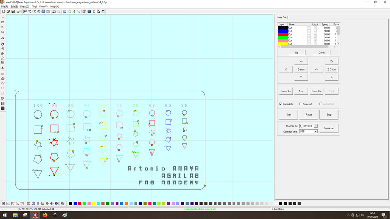
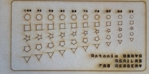
This is a table for the most common material at the lab.
Kerf
One of the group asignement was to caracterize the laser cutter and more specially the kerf. To do the kerf we had the idea to cut a square in the woodand then do multiple slices in it. I means that the laser will do many rectangles in the wood many times and we can have an average of the length of the laser. First we cut a piece of wood and mesure it.


Then we cut it in different part with straight lines. We set the laser cutter with a power at 85 and a speed at 40. We got these values in the previous test.
And finally we mesure the total size of the remainers slices. We mesure wuth the caliper.

We did again with the picometer tool but with a smaller piece of wood to fit it in the tool. We mesure it also with the caliper.


Here is the table of our different results
| Try | Size before the slices | Size after the slices | Number of slices | Average of the kerf |
|---|---|---|---|---|
| 1 caliper | 98.0 mm | 95.1 mm | 10 | 0.29 mm |
| 2 mircometer tool | 21.12 mm | 19.88 mm | 5 | 0.248 mm |
| 3 caliper | 20.8 mm | 19.8 mm | 5 | 0.2 mm |
So when we do an avergage of these values, we can say that the kerf is 0.246 mm.
Joint testing
For the group assignment we carried out a few joint tests. We decided to make the same joints on different materials to see the possible differences. So Theo made the plans on Fusion360. Then we decided to do it on 3.9mm thick cardboard, 2.5mm thick Plexiglas and 3mm thick mdf wood.


Here are our conclusions:
On the cardboard, the simple press-fit and chamfer works very well and is very accurate. For nesting such as flexure or snap, the cardboard is too sensitive to deformation. Our tests were not conclusive for these nests.

On the plexiglass our main problem was the kerf.We found that our plexiglass parts were more openwork than expected. This is due to the laser melting the material too much. In addition, we can see that the flexure nesting has been subjected to too much heat. The cutting process has deformed the whole assembly due to excess heat. Concerning the snap nesting, it is not at all adapted to plexiglass. In both cases, our parts broke, which is explained by the fact that Plexiglas does not accept a large deformation.


MDF is the material that best fits all the joints we have tested. It fits perfectly.

Focus test
In a group we carried out tests to find out the ideal focus for the machine. Our machine has the option of autofocus, which automatically adjusts itself according to the thickness of the material.
What is the interest of the focus?
The laser tube located at the rear of the machine emits a wide stream of light that must be channeled to a single point. This is achieved by using a convex lens. A convex lens refocuses the light at a single point (see photo opposite). In order to concentrate as much energy as possible on a small area, it is therefore necessary to focus. Focus is the action of adjusting the height of the material so that it is at the point of convergence of all the light beams.

Our machine make autofocus, but for the exercise we decided to focus manually. To do this we removed the honeycomb and positioned a sheet of paper on wood. We did the autofocus and measured the distance between the paper and the top of the lens. We made a laser dot to visualize the point of impact and its diameter. Then we moved around and lowered the plate. Then we made several laser points by moving the plate up.


Here are our results:


You can see that the machine’s autofocus is set correctly. Because it is at this distance that the laser achieves the smallest point.
Individual assignment
For my project of the week I decided to build this little house that I used to assemble when I was little. This kind of small chalet is very popular in France and very easy to build. With a lot of rooms you can build a lot of things.
Visualisation of kerf on 6mm MDF
- First of all I made a small piece to visualize the kerf.
- I measured the distance I had, 6.4mm instead of 6.00mm.
My kerf is therefore 0.4mm.
I will add this value to my parameters so that my pieces fit perfectly into each other.
Drawings on Fusion360
 My sketches on fusion360
Another exercise of the week was to carry out a so-called “parametric” construction. This means that values have to be entered into the CAD software. The advantage of this technique is that we can resize our plans very quickly by just changing the values in the parameter table.
Here are my different parameters:
 My table of my different parameters
What is the advantage of designing a parametric design ?
The interests are multiple: - Saving time if a value has to change - Faster in the construction of the drawing - Avoids dimensioning errors
How do I save and use parameters in fusion360 ?
To save settings, go to the ” modify ” tab and then ” change parameters “. Now just fill in your settings. Once the parameters have been defined, you need to create a sketch and add a figure to it. Use the measurement tool to determine the length of your object and enter the name of the desired function in the box. This will allow the length to change automatically if you change the values of your parameter.


AgriLab’s laser cutter only reads .dxf files, for this you need to import the basic files in this format, here’s how to import our plan in .dxf format on Fusion360 quickly and easily.

There are 3 of us at AgriLab and we only have one machine, so time is of the essence. So we have to find a setting that will allow everyone to complete their project on time. Before making my cut for my project of the week I carried out a series of tests. I decided to use 5.9mm PMT to carry out my project. Before starting the cutting of my project I made my own adjustments on the chosen material. I started by making the focus of the machine for the chosen wood (to find out how to make the focus on our machine just go a little higher). I then created a shape on LaserCut 6.1 to carry out my tests. For this I made a 40mm x 40mm square and played with the speed and power parameters. After several tests to determine the speed and power, I determined the ideal setting. For me the ideal setting is the one that cuts quickly and without heating the material too much.
Finally, I chose as a setting:
- Speed : 20
- Power : 95

Once the settings were fine-tuned I imported the different folders to cut out my pieces.
Here are some illustrations :
 Picture showing the cutting of my bars
 Picture showing the cutting of my bars
Here are all the pieces I cut out. There are 30 small bars, 20 large bars, 2 roof triangles, 2 roof slopes and a base. With this you can build whatever you want.
 The different pieces made
Assembly
Once my different pieces were cut out I assembled them together to make this little animal barn.
Or this small animal paddock.

As you will have understood, only your imagination is limiting in the construction of objects with these pieces.
Bonus
Here is the first apple Apple

At the end of the week I cut a slice of an apple and engraved the Apple logo on it using laser cutting.

Parameter for engraving an apple :
- Speed : 1000
- Power: 30