3. Computer Aided design
This week I worked on defining my final project idea and started to getting used to the documentation process.
Assignements : Model (raster, vector, 2D, 3D, render, animate, simulate, …) a possible final project, compress your images and videos, and post it on your class page
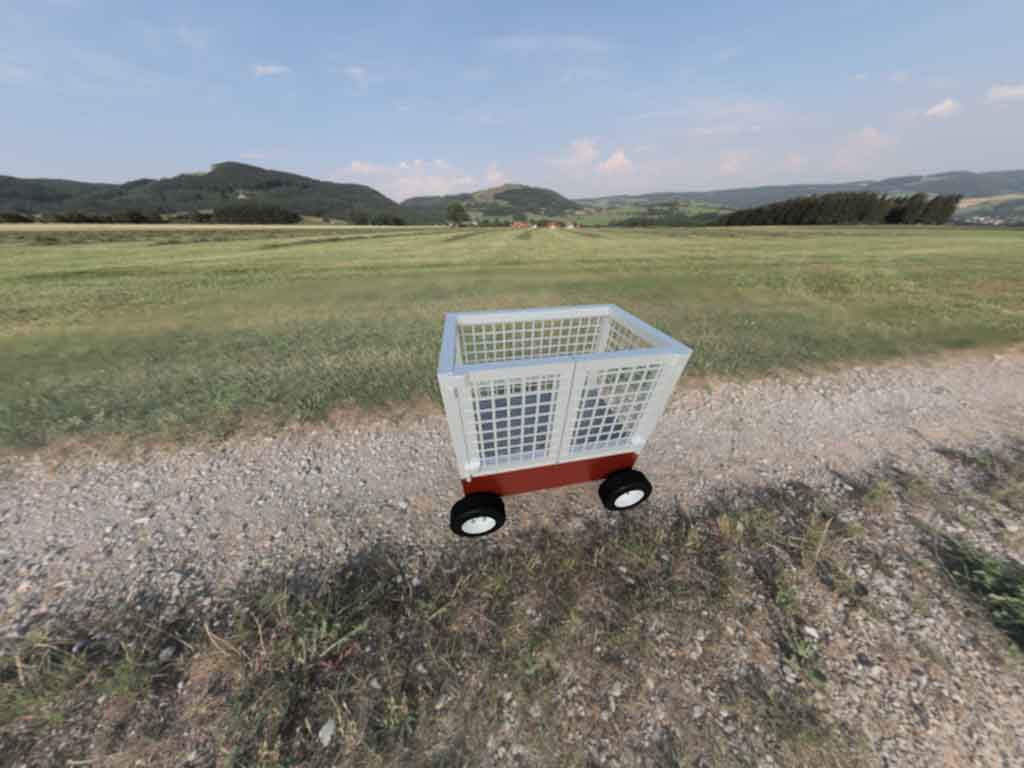
 Here is a rendering made during week 3 (CAD) with Fusion360
This week was dedicated to Computer Aided Design (CAD), so our objectives were to try out and study several CAD software packages. We had to try to make drawings in 2D but also in 3D, as close as possible to our final project.
In order to model my little robot I decided to use Fusion360 because I had already used it and it is a very powerful and intuitive software. Being still considered a student at UniLaSalle I have a free student licence for 1 year. Moreover, Fusion360 integrates very interesting rendering, animation and drawing tabs for the continuation of my project.
During this week I also took the time to try other 3D CAD software but this time open source. The advantages were multiple, first of all it allowed me to use and learn new software. Secondly, considering the price of the Fusion360 subscription, I’m not sure I would take the subscription once my education licence runs out, so I’ll have to find an open source software.
To make a 2D drawing I used Inkscape for the vector drawings and Krita for the other drawings.
3D Part
Fusion360
Fusion360 is a 3D CAD software developed by Autodesk. This software is widely used in the engineering community, contractors and designers. It allows manufacturing, simulation and rendering to be carried out in the same software.
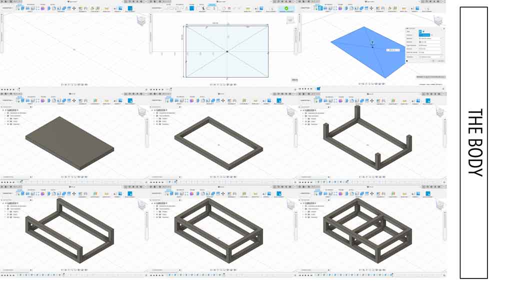
The different stages of construction of my tracking robot, first of all I designed the body :
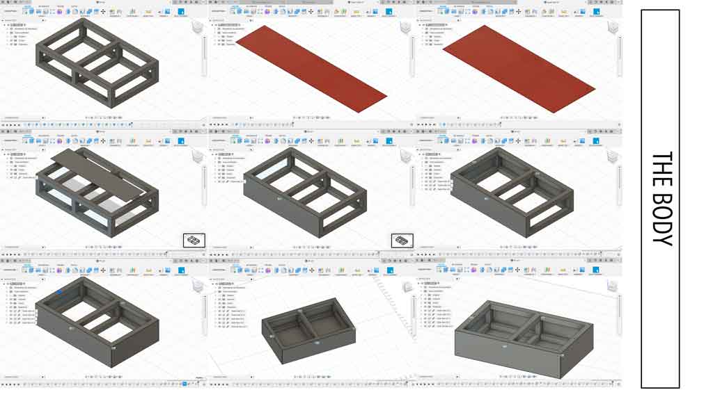
I started by making a rectangle that I extruded 40mm. Then I made a second rectangle which I extruded at -40mm to create this hole. I made several small squares with 40mm sides which I then extruded. Then I assembled my tubes together by making very simple shapes on different planes, this allowed me to make my frame. In another file, I modelled my sheets that will be on the side to close my box. Once modelled I inserted them in the active design and linked them with my frame. I then inserted screws to secure them with McMaster-Carr. Finally the last step was to make tapped holes on top so that I could later position my box.
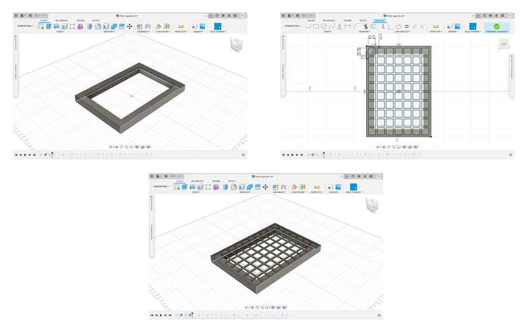
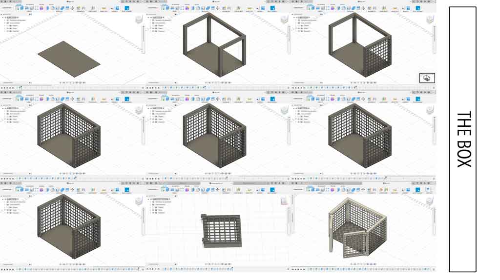
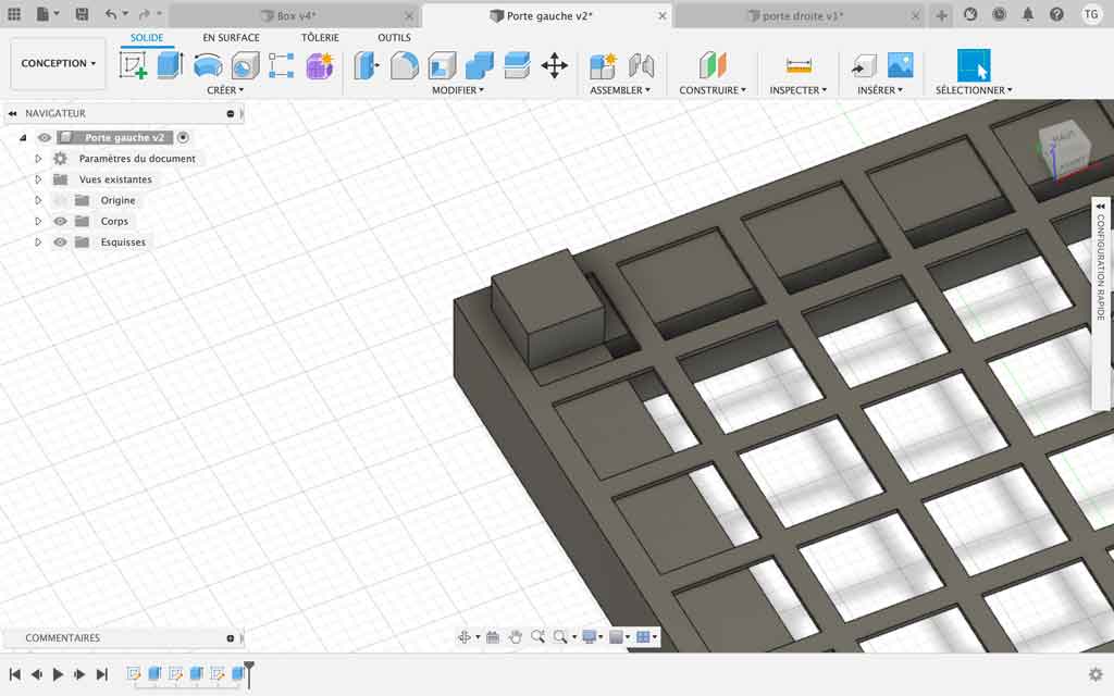
To make my box, I also started by doing very simple figures that allowed me to make my skeleton. Afterwards I made the grid. For this I made a rectangular pattern composed of 40mm squares on each side. I made this for all the faces. I then made the fixing holes to allow the link between my body and my box. Afterwards, I created hinges to allow the doors to be fitted. So I made the left and right door in another tab to insert it into my active design. To finish I played with the texture of my cage and inserted colour to the whole.
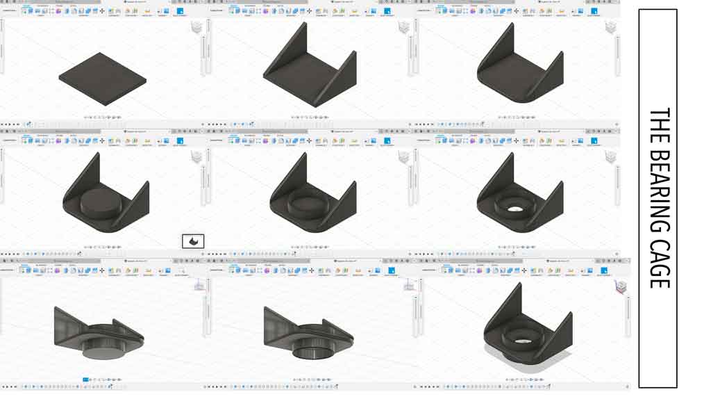
I need bearings to be able to fix my wheels. The bearings will support the weight of the set and make my rolls roll correctly. So I had to create my bearing cage by playing with the different planes. In order to have this rounded side I inserted on several filet. To make the bearing cage itself, I extruded a circle. After I make a a hole with a flat finish of the desired diameter. I carried out this step on both sides to finally drill the hole in the middle so that my wheel axle could pass through. Finally I added a black appearance.
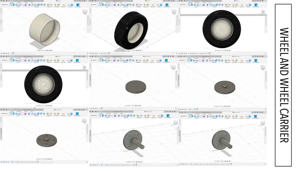
My robot needs wheels to be able to move forwards or backwards. As I hadn’t yet found out exactly which wheels I was going to choose for my final project I designed a very simple wheel. So I made a revolution around an axis to make the rim and then I recreated a plan for a revolution to make my tyre. I was then able to model my wheel support.
Before carrying out this step I have modelled my different pieces in different files. I find this easier for projects like this one. Moreover by making links between the files and the assembly it allows you to have active modifications. This means that if I make changes to the wheel, then automatically the change will appear on the assembly.
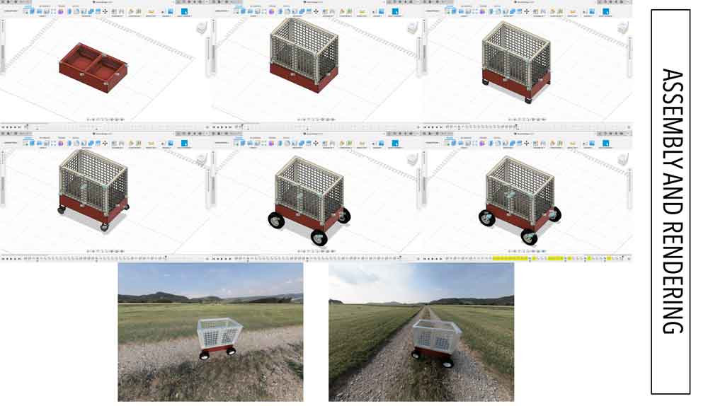
Once all these steps were completed I was able to assemble the whole thing and make a rendering. So I started by inserting my robot body, then adding the basket with the fixing screws. Then I positioned the bearing cages and inserted bearings found on McMaster-Carr. Finally I added my wheels and its mounting screws.
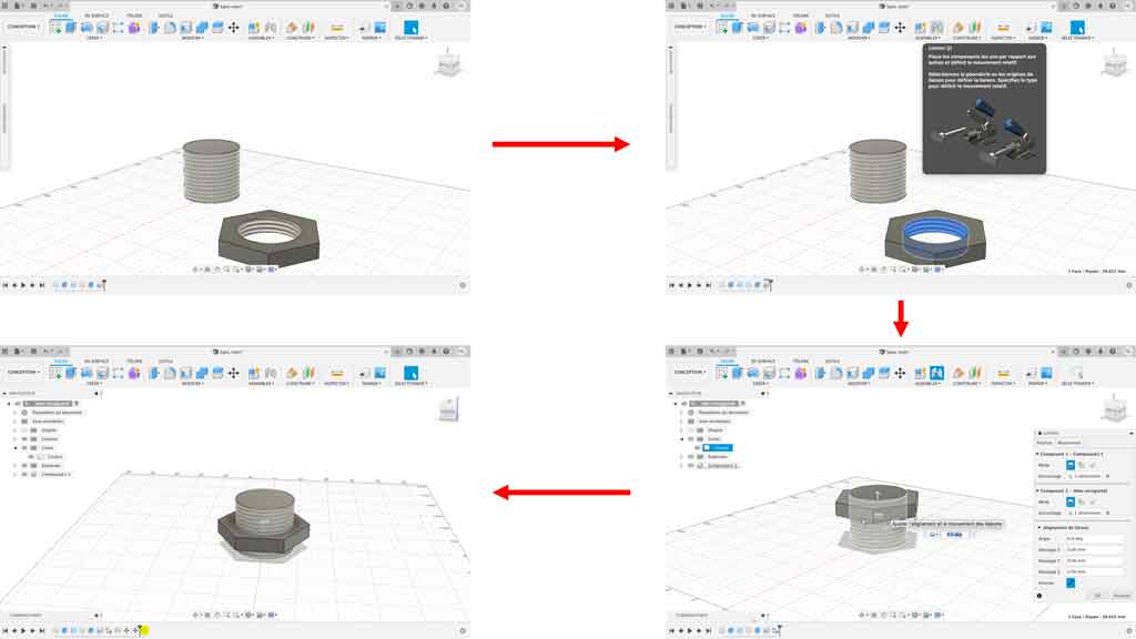
How do I make a joint ?
To make a connection between two parts, simply select one side of the component and then click on the joint icon. Then click on the other side of the object you wish to link together. To finish it is enough to move the object with the arrows if this one is not positioned at the exact place.
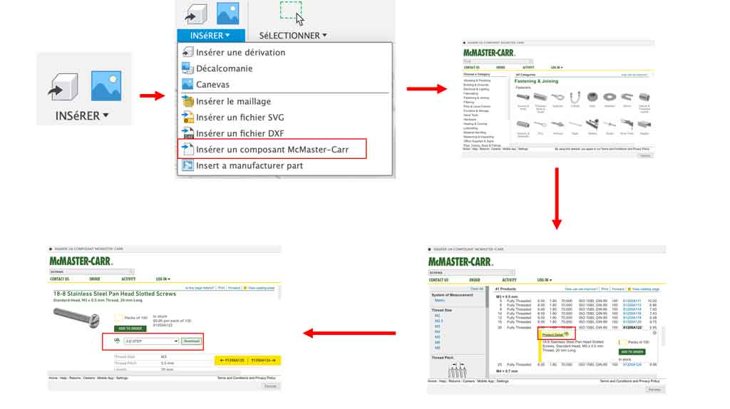
How do I make a McMaster Carr insertion ?
It’s very simple, just click on the insert button and then click on insert McMaster-Carr component. A dialogue box will open and you will have to find the object you want. In this example I would like to insert a screw. Once you have found the object you want, click on product detail CAD and download the object in 3-D STEP format. Once all these steps have been completed you can move your object wherever you want.
Render
To make a rendering just go to the rendering tab. Then open the rendering settings and play with the different parameters. You could then export your image by clicking on the download icon.
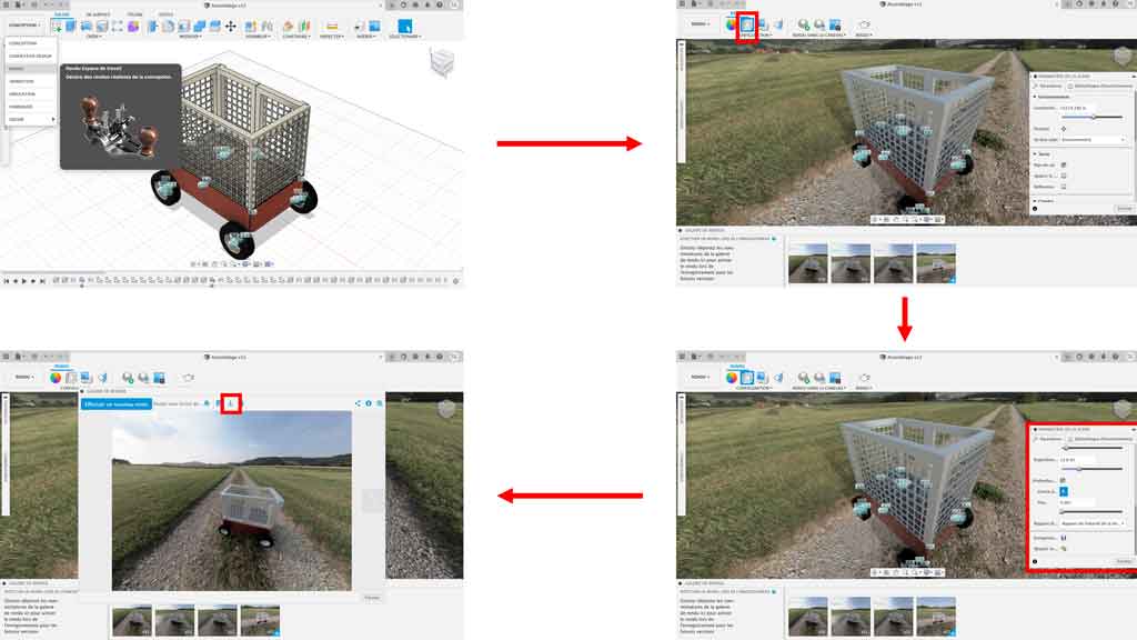
I went to the rendering settings to set a background, played with colour and brightness. Here are some pictures of the rendering I was able to do.
Create an animation
It seemed interesting to me in view of the time I had left to make a small animation of my project. So I did some research on the internet to make an explosive type of realization. I found a tutorial on Youtube to explain it to me.It’s very simple, just click on automatic burst: all levels or on the keyboard shortcut U. Then all you have to do is move the elements in the assembly plan. Here is a quick overview of the animation.
My mistake
I spent a lot of time trying to understand why I couldn’t extrude my square over the entire surface drawn on the plan. After a few minutes of reflection I tried to remove the mesh and then redo my drawing and extrusion. It worked!
FreeCAD
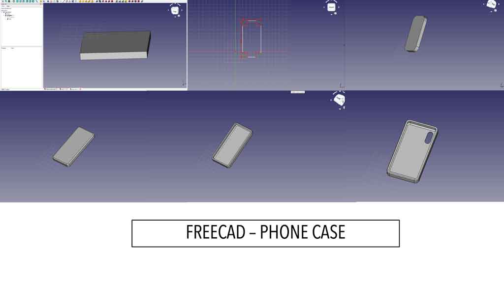
As said in the introduction I had the chance to try several software packages. In a second step I chose to use FreeCAD . For this little exercise I decided to make it quite concrete so I chose an object that was around me and easy to model. So my gaze came very quickly to my phone and therefore to my phone shell. So I quickly handled the software by making a simple shape with rounded corners. Here are some pictures of this exercise :
Blender
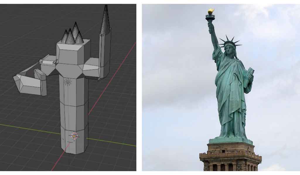
At AgriLab we have some courses on different software like FreeCAD or Blender. When I was told that Blender was to make more artistic forms, I went straight to the games. With a few extrusions and a lot of imagination I tried to reproduce the Statue of Liberty of New York, so it looks similar, doesn’t it?
I decided not to take FreeCAD or Blender because I didn’t find these software very powerful and intuitive for my project. Moreover FreeCAD does not have all the features of Fusion360 and it is simpler to stay on the same software for design, rendering, animation and drawings.
2D Part
For the 2D part we had several courses at AgriLab on two different softwares, a vector drawing software like Inkscape and a raster drawing software like Krita.
What are the advantages and disadvantages of these two softwares?
| Inksape (vector drawing) | Krita (raster drawing) | |
|---|---|---|
| Advantages | - Possibility to overwrite or stretch the image without loss of quality - Lossless image compression in quality - Smaller file size - Possibility of tailor-made retouching | - High definition of colours and brightness - Each pixel can be retouched |
| Inconvenients | - Needs to be created on a dedicated software - Be careful when creating as small invisible errors may be revealed when enlarging | - Impossible to enlarge a lot without losing quality - Rather heavy file if it is not compressed (but compression causes loss of quality) more complicated to change quickly |
Inkscape
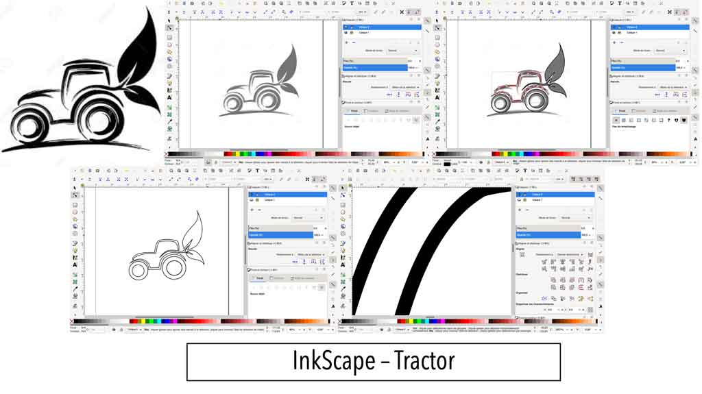
For Inkscape I decided to design a tractor. For this I looked for a picture on the internet that I liked. I downloaded it to my computer and imported it to Inkscape in a layer. Then I used the “Bezier curve” tool to make lines above the layer. With the little brackets I was able to stretch my curve so that the lines of my layer follow perfectly. Here is the result step by step.
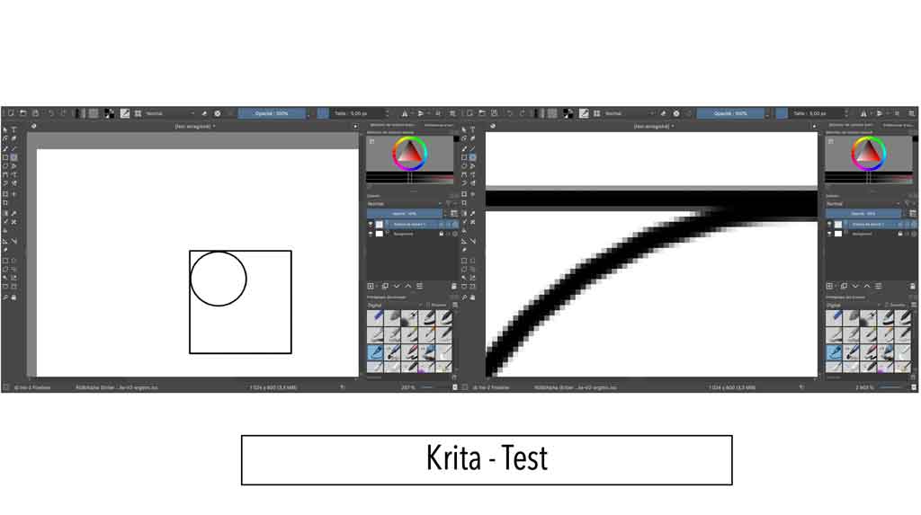
Krita
I used Krita very little during the week but I wanted to show you the difference with Inkscape. I made two very simple shapes, a square and a circle. You can see that when you zoom in on the edges of these figures the pixels appear.