3D Scanning and Printing
- Test the design rules for your 3D printer(s)
- Design and 3D print an object (small, few cm3, limited by printer time) that could not be made subtractively
- 3D scan an object (and optionally print it)
I have the chance of having my own 3D printer at home, an Ender 3 V2. So this week is not an entire discovery for me, even though I am far from being an expert in 3D printing. I will sease this chance to dive a little deeper in the slicers available (I want to test new ones, I used Cura for now) and to push my knowledge farther. I also want to have a nice documentation of my printer to come back when needed, and I would like to install my CR-touch this week-end. Finally, I want to test the printers on the lab: we have a Raise 3D printer and an Elegoo Mars 2 for resin printing. We also have TPU filament which would be a change from PLA as usual. I have the feeling it will be a busy week as well as the previous one, so let’s get into it !
My planning is almost booked for the days to come, I must keep to it and make the best of my available time.
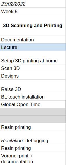
Here is an hero shot of this week with all my printed objects. I hope you’ll enjoy reading 
Structured Light Scanning
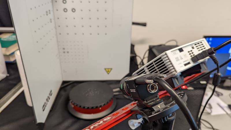
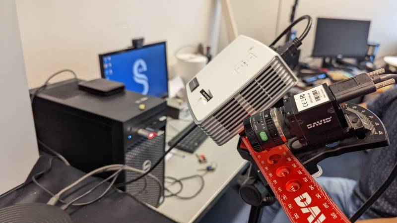
The Sorbonne university owns a David 4 scanner: I searched it online but unfortunately it seems the technology was bought by HP and there is no updated informations yet. But the experience was fun, thanks to Pierre who kindly showed me his equipments. He told me some students use this technology to scan fossils in a very accurate manner, with impressive results (but lot of time spent). I used the scanner for three hours and it was hard enough: the David software is kind of old and crash very often, it’s not very friendly.
Calibration
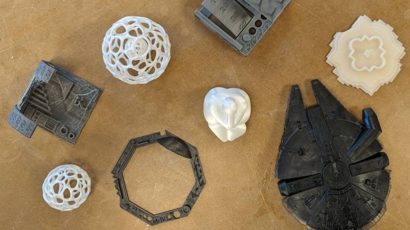
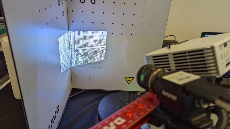
The scanner we used is based on structured light technology.
We first need to calibrate the scanner by projecting a light pattern on the surface to be scanned: it applies a form of triangulation calculation. When projecting the pattern, we need to focus the camera on the background. You can see on the two pictures below the pattern and its appearance on the software.
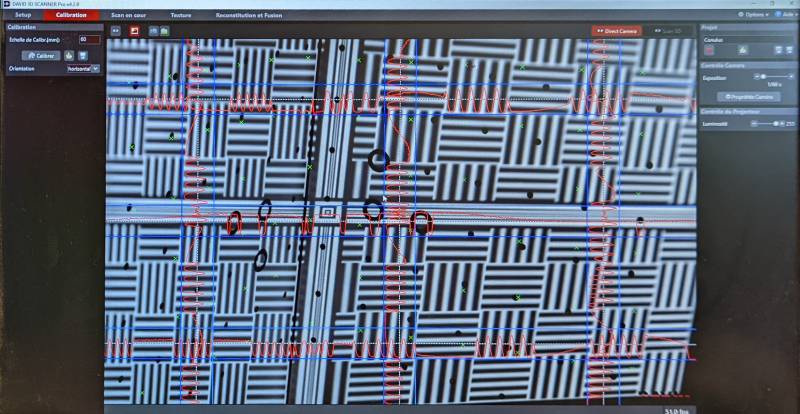
When calibrating, the pattern changes very quickly, as you can see on the video. The scanner needs to know the position of the pattern to be prepared to calculate points distorsion when we put an object on the turning table.
Scan
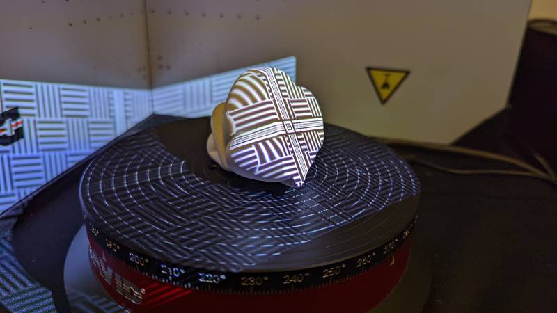
Then we can put an object on the scanning table and choose how many scans we want: the more the better, but it can take a long time. We chose to scan the object from eight different angles.
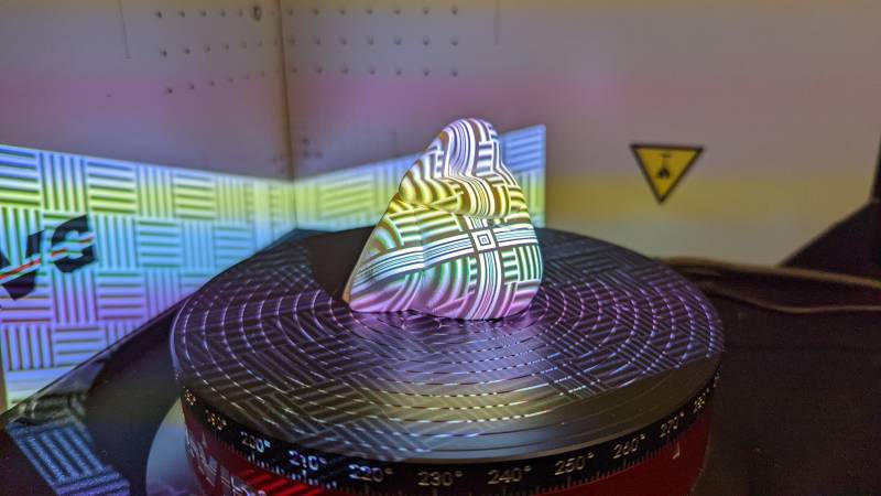
As you can see on the video (accelerated four times), the turntable is doing all the work for us. The 3D scanner will capture the deformation of the pattern projected by the light and calculate its displacement. It can then deduce the properties of the surface.
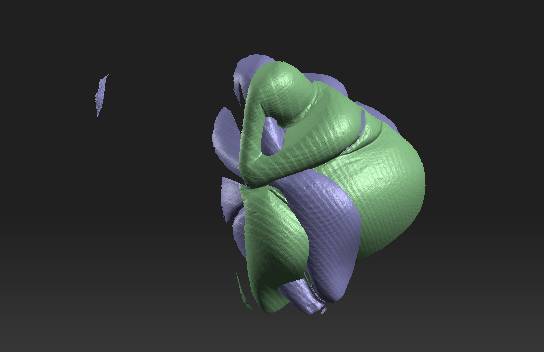
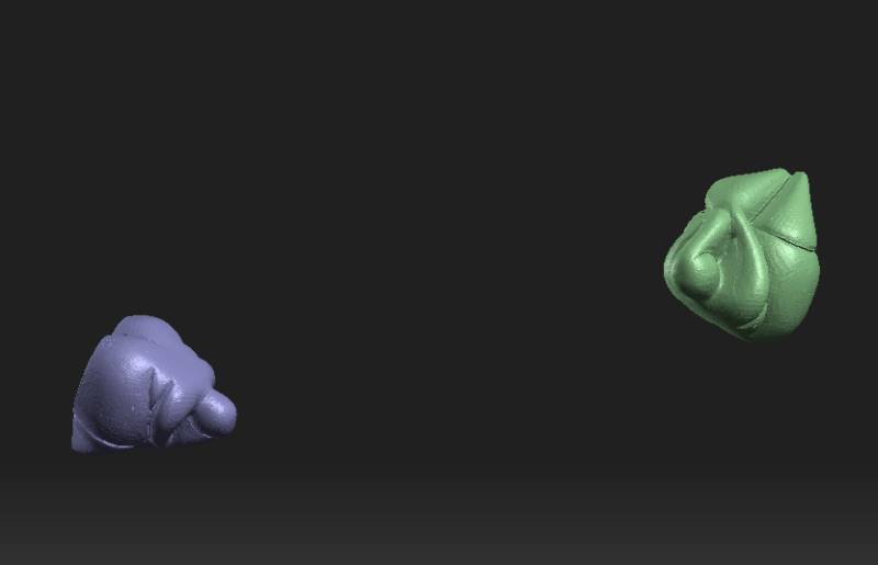
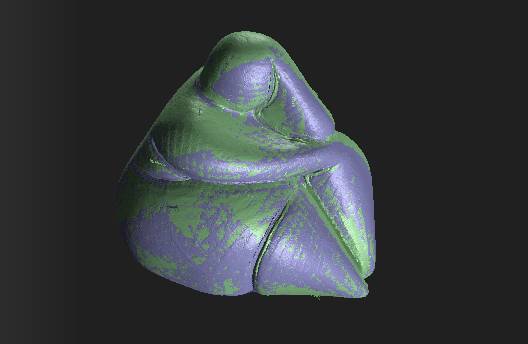
Every scan is incorporated in the software. We can observe one scan on the left picture below, and the mix of two scans on the right picture. There is also a small purple part on the left of the two scans: we will need to remove this before the fusion.
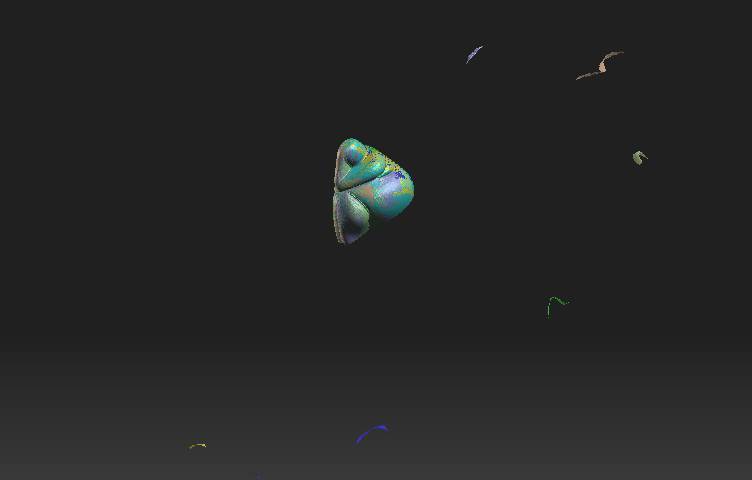
You can see that all scans have been merged on the software. When the small parts are removed it makes a fairly clean scan. We removed the ones who were too displaced.
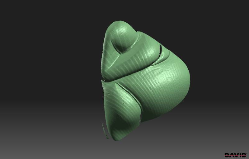
We made another scan to have the bottom of the figure. Once it was done, we had 16 scans of the figure merged in two groups.
Once aligned, the two groups formed a great scan of the figure!
Fusion and export
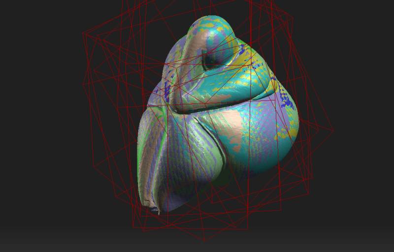
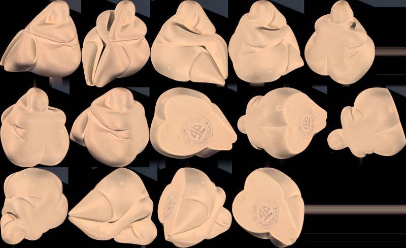
We can now export the scanned figure into an STL file. The David software gives us a bonus file that shows which scans were used for the fusion, as you can see below.
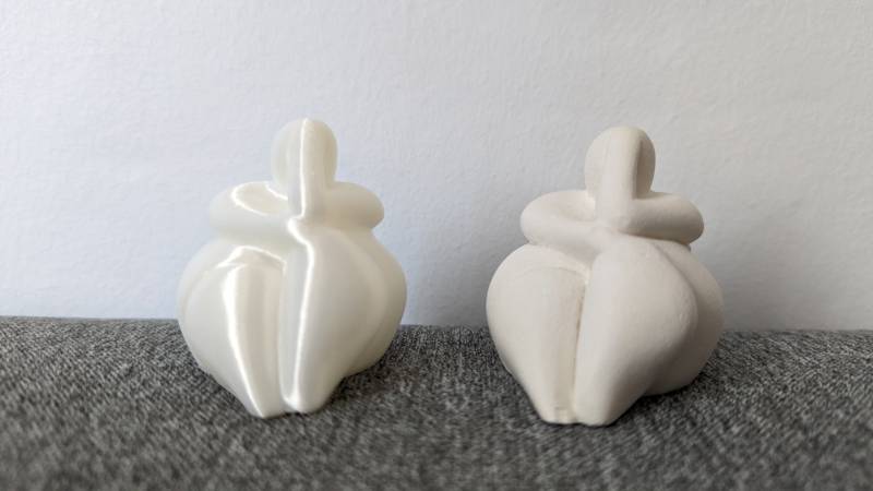
The result is way better than I expected: I tried scanning things before with my phone but were never close to this kind of results
Print
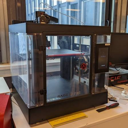
I decided to try the Raise 3D Pro2 we have at the lab instead of mine. I used ideaMaker, the official slicer for these printers.
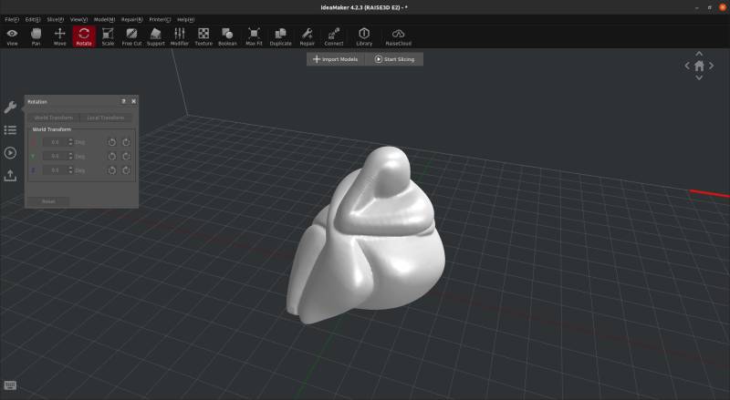
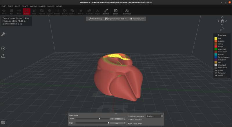
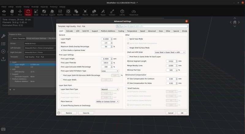
I chose to print the scanned object with layers of 0.1mm to obtain a good print, similar to the original. I used simple PLA because it’s the medium I know best. I hope to try other filaments this week. As the scanned figure was not entirely flat, I put it slightly beyond the printer plate on the slicer. It created a false flat surface for the bottom and did the trick.
The first test was an epic fail: we levelled the bed and tried again with better result.
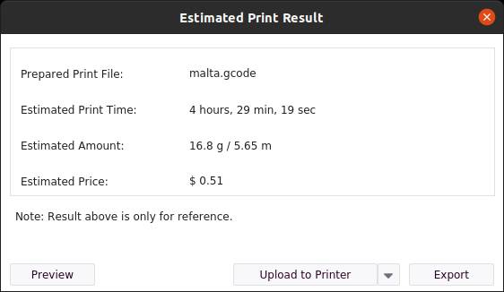
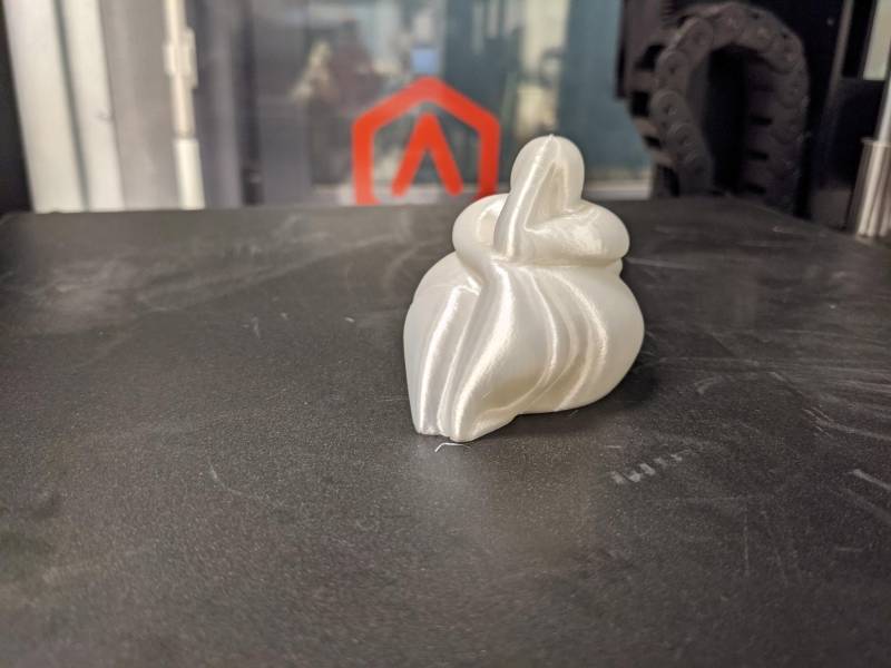
It took two tries and nearly five hours but the result is very good!
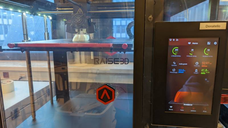
The Raise 3D allows us to get a timelapse of the print afterwards.
Resin experience
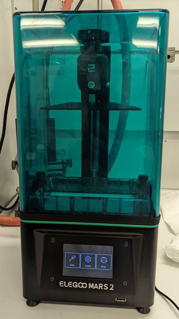
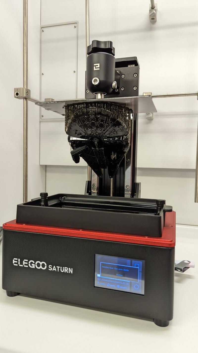
For my final project I need to print the fountain I modelized during the Computer Aided Design week. I wanted to take this week as an opportunity to test the parameters for the resin printers we have at the lab. We have an Elegoo Mars 2 and a brand new Elegoo Saturn I helped installing.
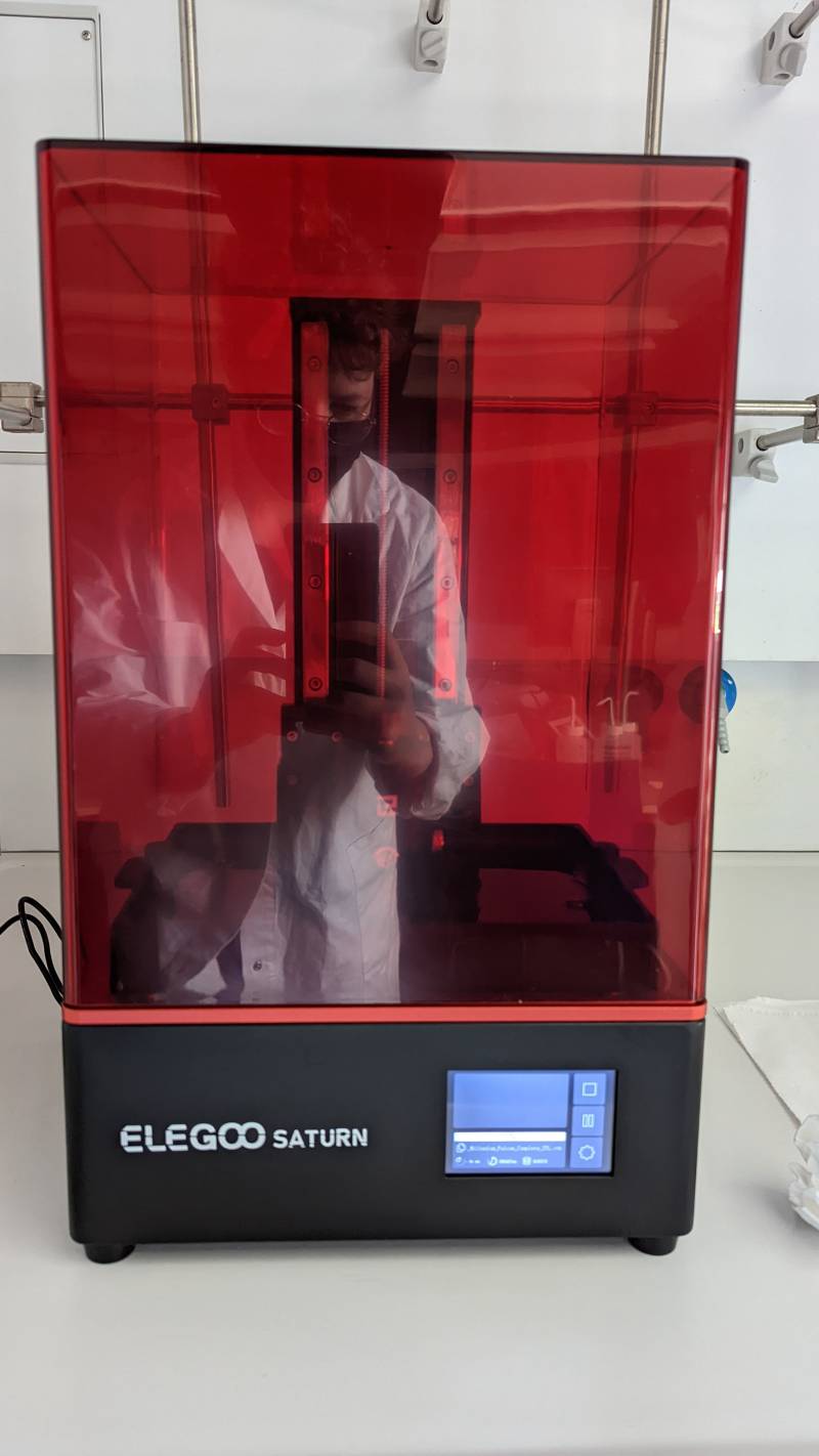
You can see my reflection on the Elegoo Saturn: a lab coat is not mandatory when manipulating resin, but it can help keep your clothes clean. I also wore gloves when pouring resin into the printer.
Prepare the print
Running Chitubox 1.8.1 on Ubuntu 20.04
The first time I tried to run Chitubox I got stuck with this error:
./CHITUBOX: error while loading shared libraries: libQt5Quick.so.5: cannot open shared object file: No such file or directory
Thankfully, I found a fix on this forum discussion.
Then start the app with./AppRun
To avoid running these commands everytime I want to use Chitubox, I enclosed them in a script.
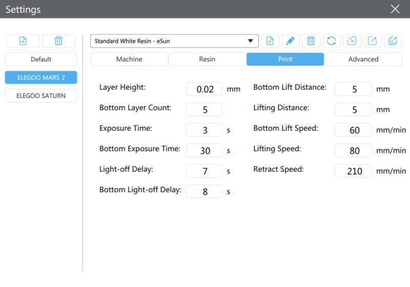
Chitubox is not that different from others slicers I used for PLA printing so I was not that lost. The main difference is in the parameters, because you have to take count of the exposure time of each layer. The bottom layer must be exposed much longer than the regular layers because of the risk of loosing the part. Below you can see which parameters I used for a standard resin.
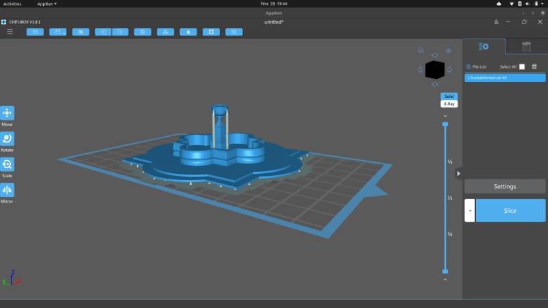
We need supports with resin printing as well as with FDM. As we had a flat base with the fountain we could have let it without supports, but I was afraid of ripping off the base during the post-process. Simon advised me to put the model 2mm above the plate and let supports do their job: I will be able to remove them without destroying the base.
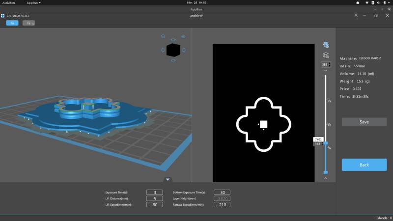
When the slicing was done, it was time to prepare the printer: the slicer indicated that we needed ~22ml of resin for the print: we put 30ml to be safe. You can see our workspot on the picture below. It’s important to keep the printer steady because a tiny vibration can have a very important effect on a layer.
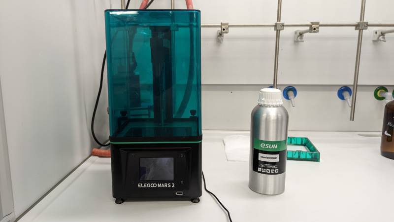
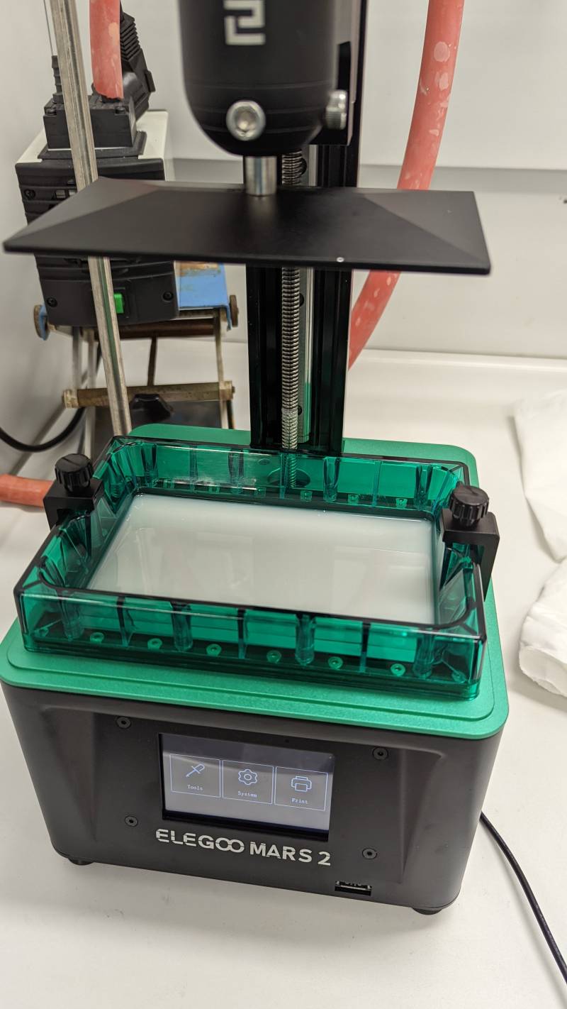
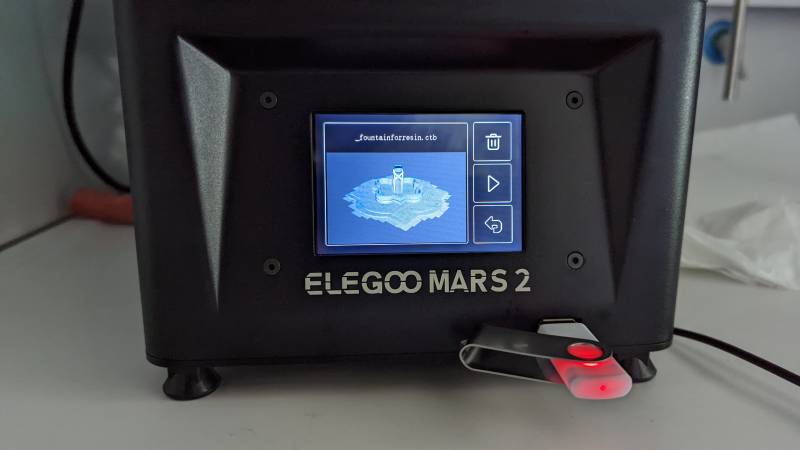
I poured the resin into the tank next to the printer: I could have done it with the tank already in place but it’s not safe for the screen if the tank is pierced. After pouring our 30ml of resin, I put the enclosure on the printer and inserted the USB stick to transfer my file. You can see the visualization of the print on the screen.
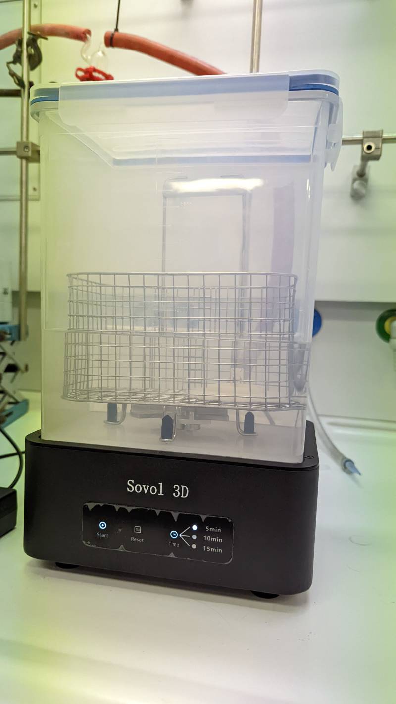
Post-processing
Warning
Remember to work in a well ventilated area: the solvent can be hazardous.
-
Remove the piece with a plastic spatula
-
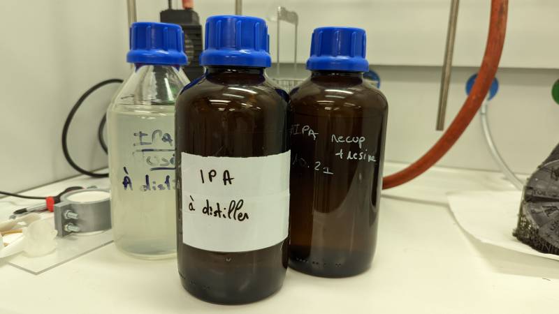
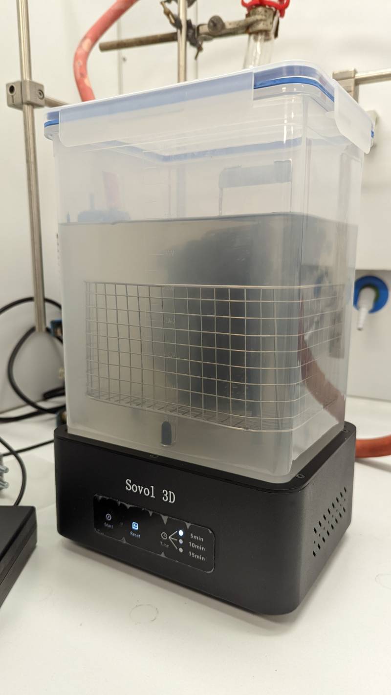
Place the printed part in a tray of IPA solvent and shake gently
-
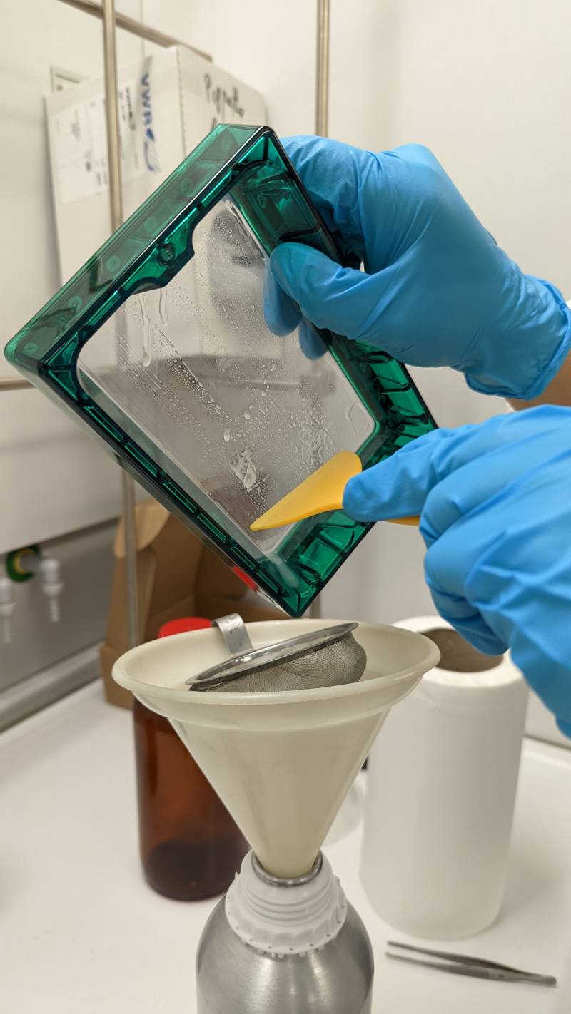
Meanwhile, collect and filter the resin
-
Clean the tray with clean cloths and use a cloth lightly soaked in solvent for the remaining resin (especially in the corners)
-
Remove the part from the solvent tray and drain it
-
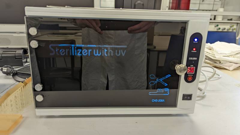
Expose the piece to UV light
-
Clean everything with warm water and soap
-
Remove the supports and enjoy the result!
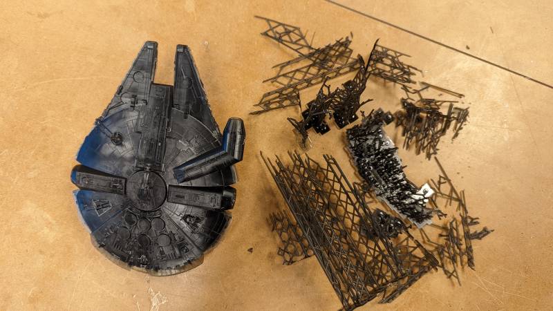
Bonus: Millenium Falcon
We had fun testing the Elegoo Saturn for the first time with a model of the Millenium Falcon found in Thingiverse.
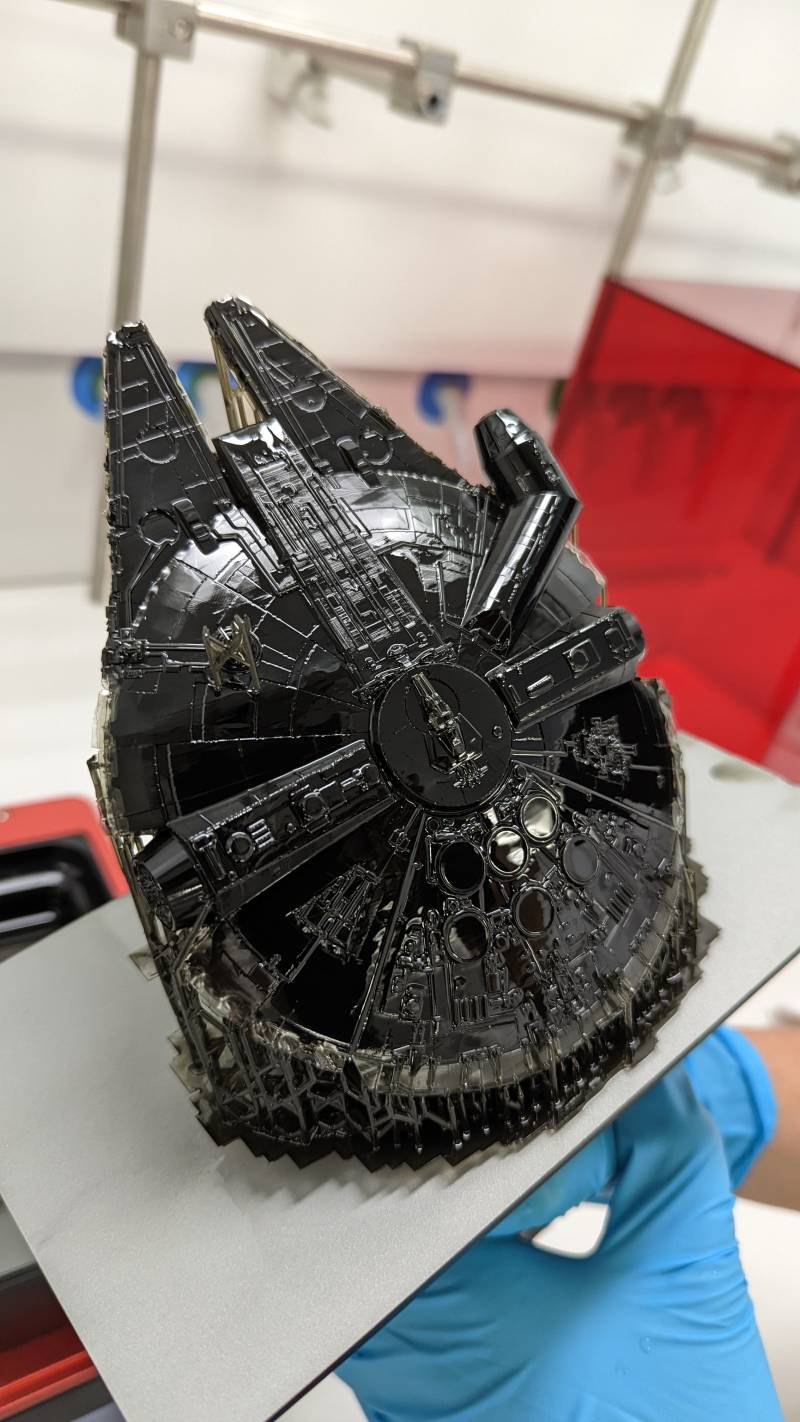
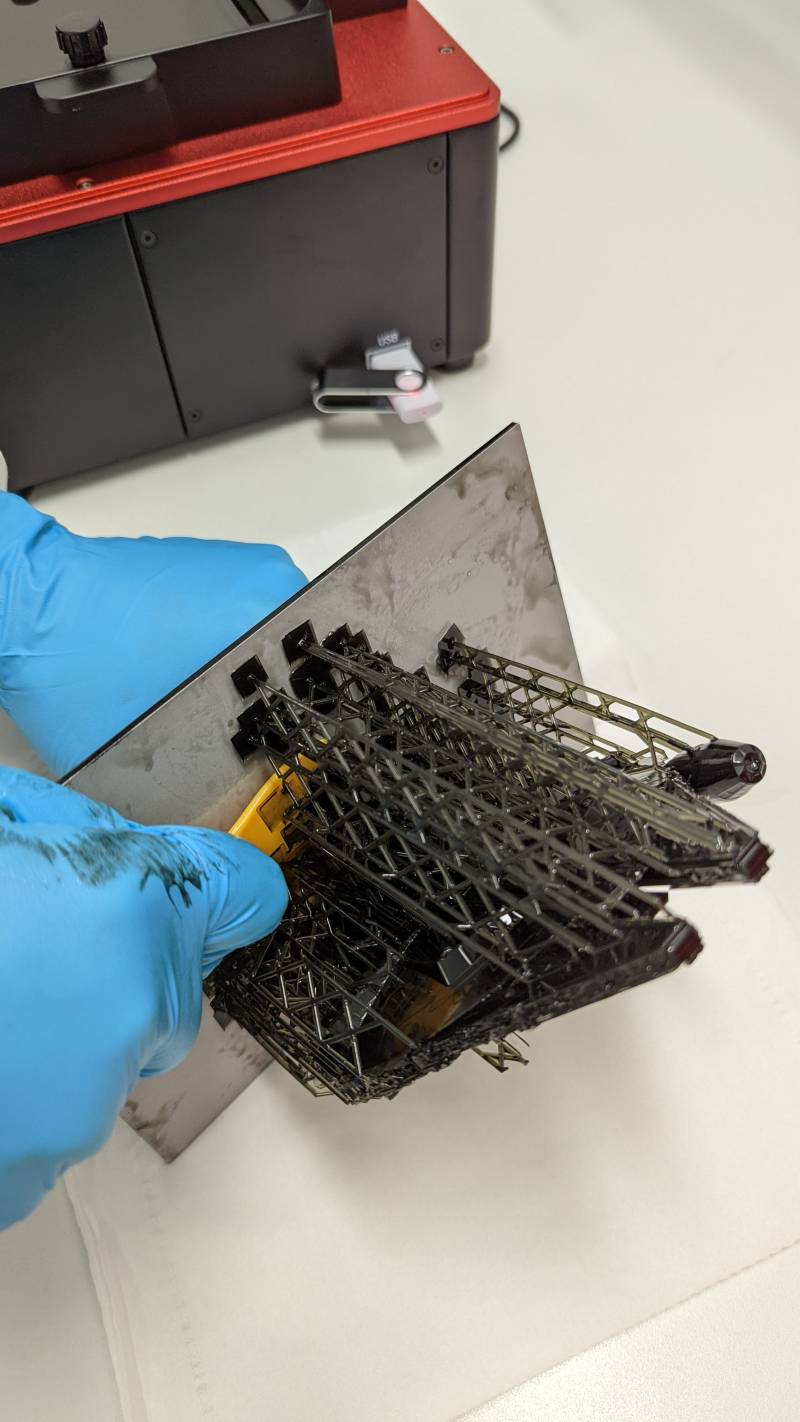
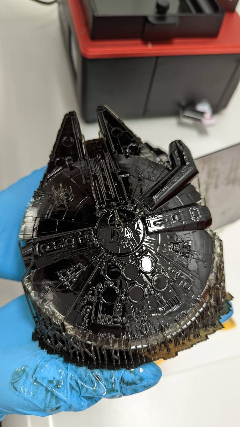
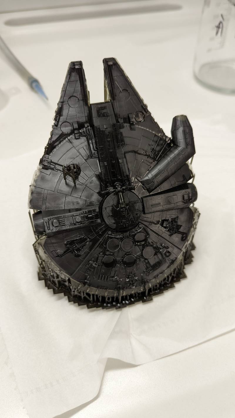
The result was great, it just lacked some details on the bottom part that were too thin to resist the solvent bath. Overall it was a good firt test, it shows how far we can go with a model!
Design for 3D Printer
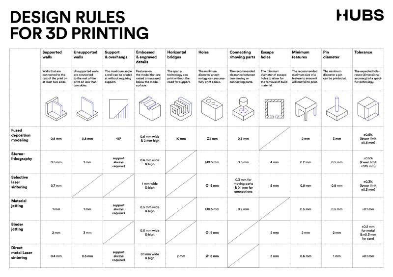
My instructor Stephane gave me at the beginning of the week The 3D Printing Handbook by Tony Fadell. I haven’t read it entirely of course, but I would say it’s a must have when you want to dive into designing for your printer. I especially liked the design reminder poster:
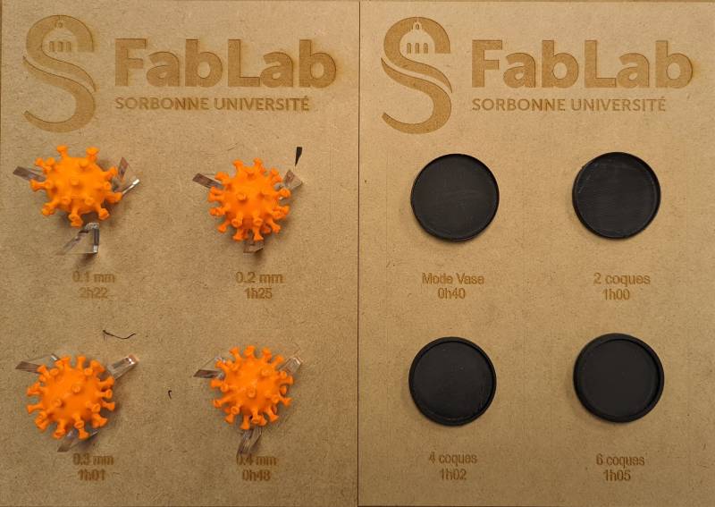
We also have examples in the lab that I love to check before slicing. I will make some for my future lab if I have the chance
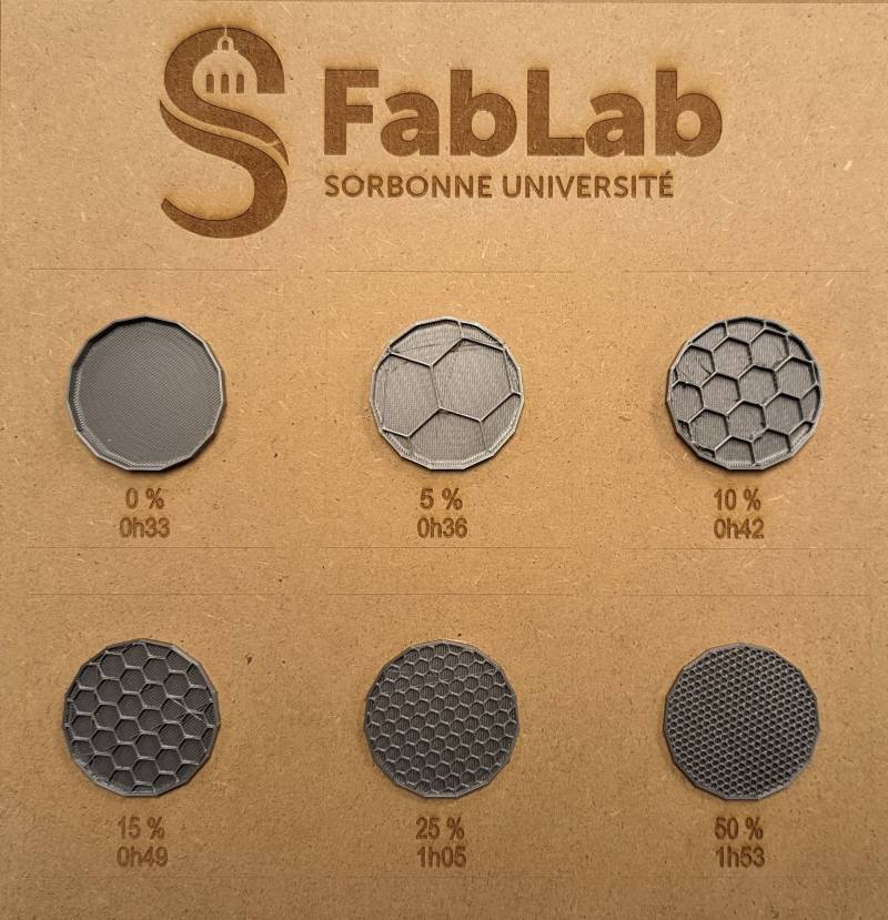
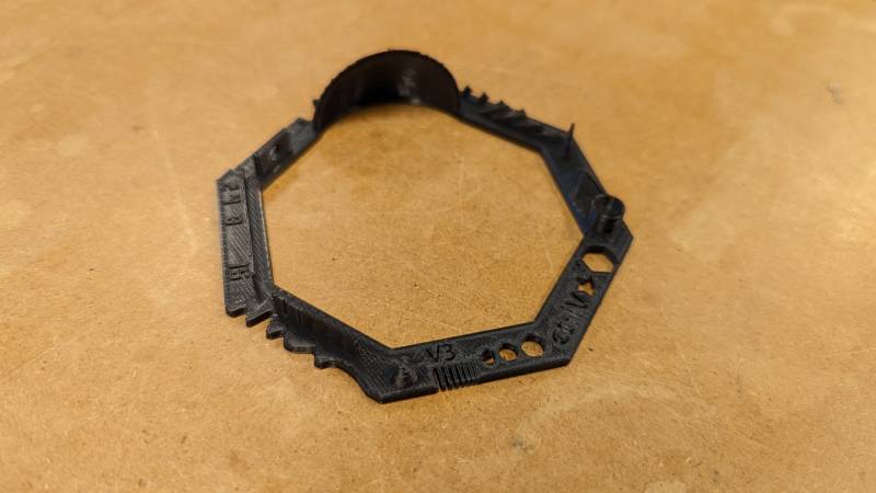
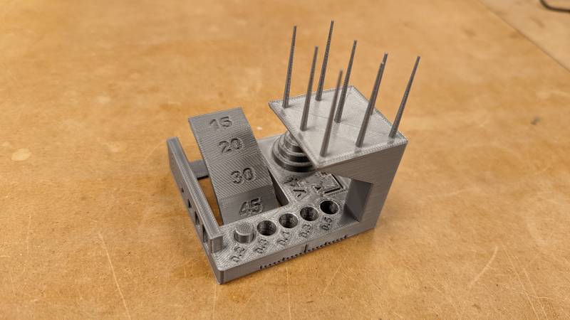
Testing the limits of the machine
On the Raise3D Pro2 at the lab though, we had very good test results: these are expensive machines and if the first layer is good and your parameters reasonable, there is no reason for a fail.
“Design a piece that could not be made substractively”, said Neil
Time to use Blender again! I would like to make a cat toy with a ball-in-a-ball kind of object. Adrian aldso advised me to look into Voronoi pattern and I loved the idea.
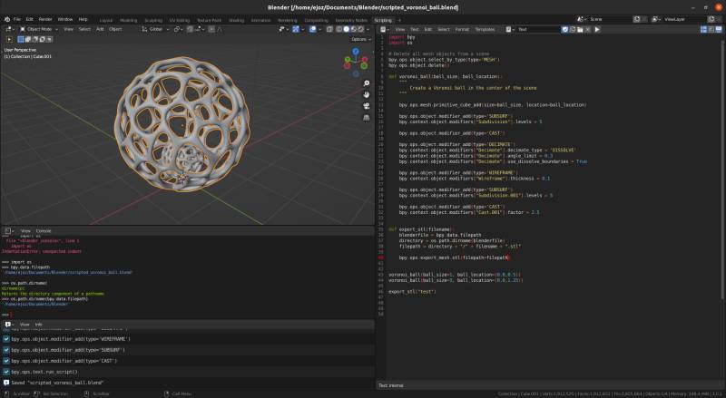
I followed this tutorial about creating a parametric voronoi ball in Blender. After tweaking the model a bit, I decided to give a try to the Python console I noticed during the Computer Aided Design week. I followed this tutorial to learn how to add basic mesh in Blender and experimented a bit with the modifiers to find the right parameters.
With the following script, you will be able to have your own Voronoi ball!
bpy.ops.mesh.primitive_cube_add(size=ball_size, location=ball_location)

bpy.ops.object.modifier_add(type='SUBSURF')
bpy.context.object.modifiers["Subdivision"].levels = 5

bpy.ops.object.modifier_add(type='CAST')

bpy.ops.object.modifier_add(type='DECIMATE')
bpy.context.object.modifiers["Decimate"].decimate_type = 'DISSOLVE'
bpy.context.object.modifiers["Decimate"].angle_limit = 0.3
bpy.context.object.modifiers["Decimate"].use_dissolve_boundaries = True

bpy.ops.object.modifier_add(type='WIREFRAME')
bpy.context.object.modifiers["Wireframe"].thickness = 0.1

bpy.ops.object.modifier_add(type='SUBSURF')
bpy.context.object.modifiers["Subdivision.001"].levels = 5

bpy.ops.object.modifier_add(type='CAST')
bpy.context.object.modifiers["Cast.001"].factor = 2.75
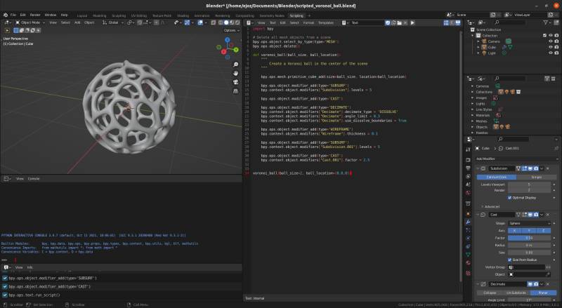
I enclosed the mesh creation in a function to have fun with this kind of script:
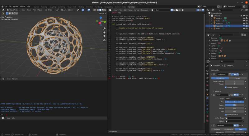
As I had my cat toy in mind I did a ball-in-a-ball and voilà!
voronoi_ball(ball_size=1, ball_location=(0,0,0.5))
voronoi_ball(ball_size=3, ball_location=(0,0,1.25))
I added a convenient export function to my script. I know I will use Python in Blender again, this is awesome!
import bpy
import os
# Delete all mesh objects from a scene
bpy.ops.object.select_by_type(type='MESH')
bpy.ops.object.delete()
def voronoi_ball(ball_size, ball_location):
"""
Create a Voronoi ball
"""
bpy.ops.mesh.primitive_cube_add(size=ball_size, location=ball_location)
bpy.ops.object.modifier_add(type='SUBSURF')
bpy.context.object.modifiers["Subdivision"].levels = 5
bpy.ops.object.modifier_add(type='CAST')
bpy.ops.object.modifier_add(type='DECIMATE')
bpy.context.object.modifiers["Decimate"].decimate_type = 'DISSOLVE'
bpy.context.object.modifiers["Decimate"].angle_limit = 0.3
bpy.context.object.modifiers["Decimate"].use_dissolve_boundaries = True
bpy.ops.object.modifier_add(type='WIREFRAME')
bpy.context.object.modifiers["Wireframe"].thickness = 0.1
bpy.ops.object.modifier_add(type='SUBSURF')
bpy.context.object.modifiers["Subdivision.001"].levels = 5
bpy.ops.object.modifier_add(type='CAST')
bpy.context.object.modifiers["Cast.001"].factor = 2.75
def export_stl(filename):
    """
        Export all meshes in an STL file in the same directory
    """
    blenderfile = bpy.data.filepath
    directory = os.path.dirname(blenderfile)
    filepath = directory + "/" + filename + ".stl"

    bpy.ops.export_mesh.stl(filepath=filepath)
if __name__ == "__main__":
voronoi_ball(ball_size=1, ball_location=(0,0,0.5))
voronoi_ball(ball_size=3, ball_location=(0,0,1.25))
export_stl("voronoi-cat-toy")
I couldn’t share my Cat toy model on Sketchfab because of its size: too much modifiers I’d say. As I shared the script I hope it is easily reproductible.
A simple Voronoi ball created with the script above:
Printing the Voronoi balls
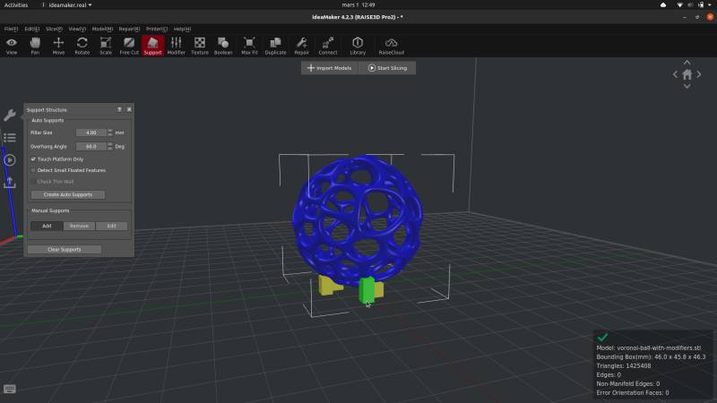
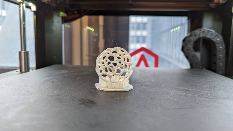
It was tricky to get there: I first tried to push the printer to print without support but it failed eventually because the ball rolled… Predictable.
So I added supports to maintain the ball during the print. It’s funny because the Voronoi pattern is ideal for a non-supported print, but the ball make it difficult to rest in place.
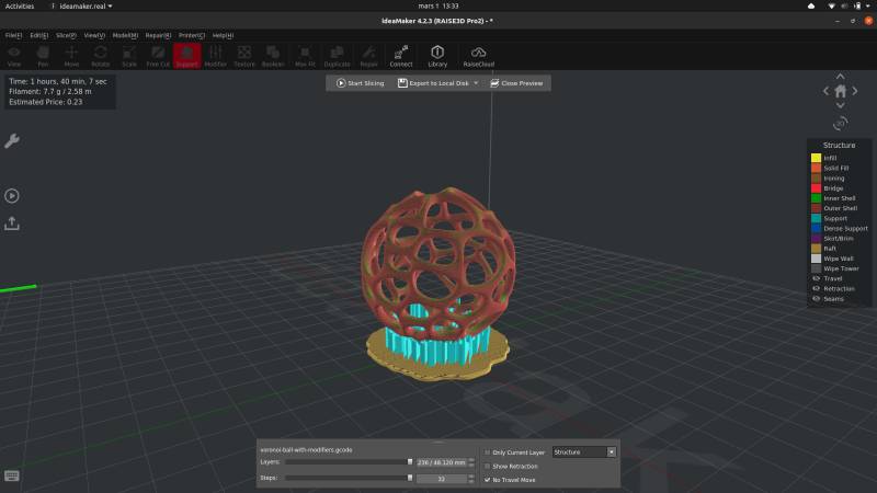
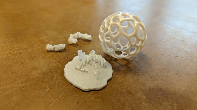
The result is quite good but need sanding on the bottom. Not as bad as I expected though!
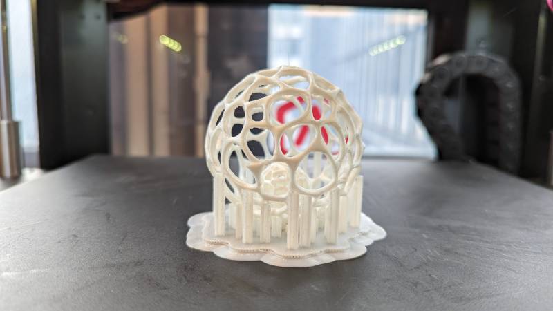
For the cat toy I rely on the hope the little ball will be supported enough to not move, but not be stuck to the big ball. You can see on the video below I tried to add supports to avoid it rolling (as it appened with the simpler model). The print lasted four hours.
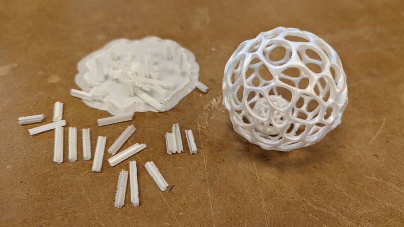
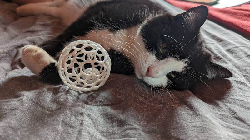
The result was very good and worked as expected. Once the supports remove, the ball inside detached from the big ball and rolled easily!
She loves it (I think so)!
Final project: sculpting mode in Blender
With the resin printers I had the opportunity to go a little farther than usual in the details of my 3D models. I wanted to explore the sculpting mode in Blender, so I added the sculptures on the fountain I previously made. It is not that ressembling, but I have a better grasp on the sculpting mode now. I should hope that practice will make my 3D organic modelling skills more acceptables.
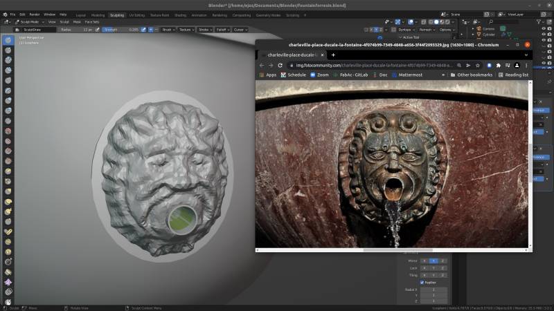
You can see the 3D model of the fountain with the sculpted “lions” below.
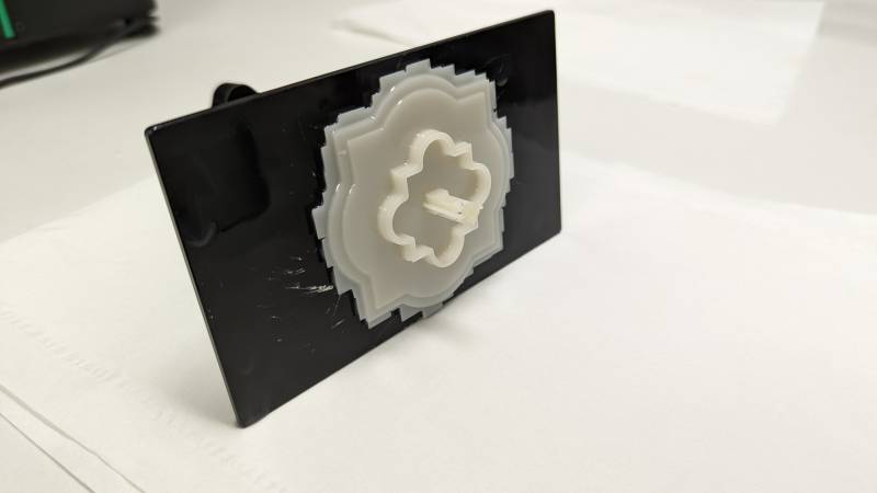
Unfortunately the first test with the resin printer wasn’t at all large enough to keep the details. It was my first time with the printer, so I didn’t know what to expect and wasn’t really good at anticipating.
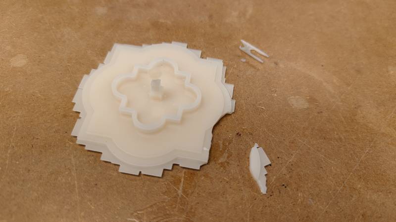
I learned a lot though, and I think I can make it work with a bigger resolution: I will slightly change my original designs for the diorama to have a bigger fountain, printed in several parts. I will reduce the diorama to two houses to keep the scale reasonable.
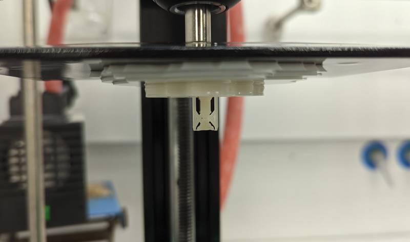
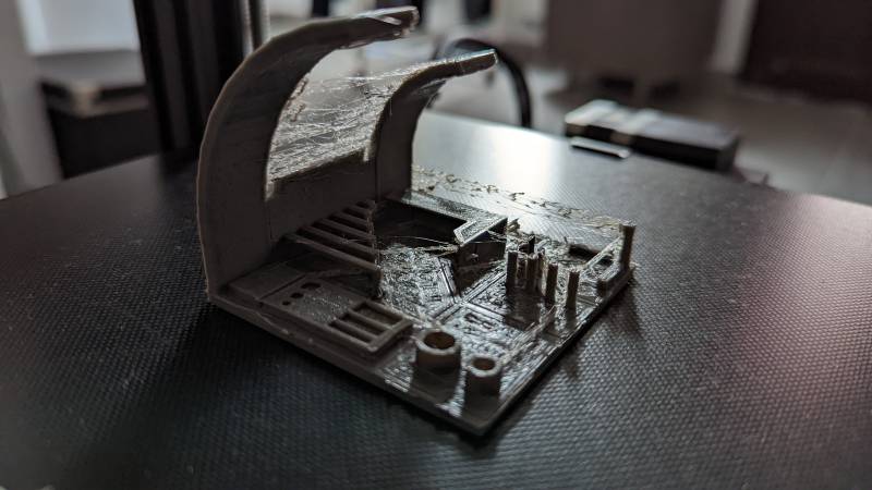
Automatic bed levelling: installation of a CR-Touch
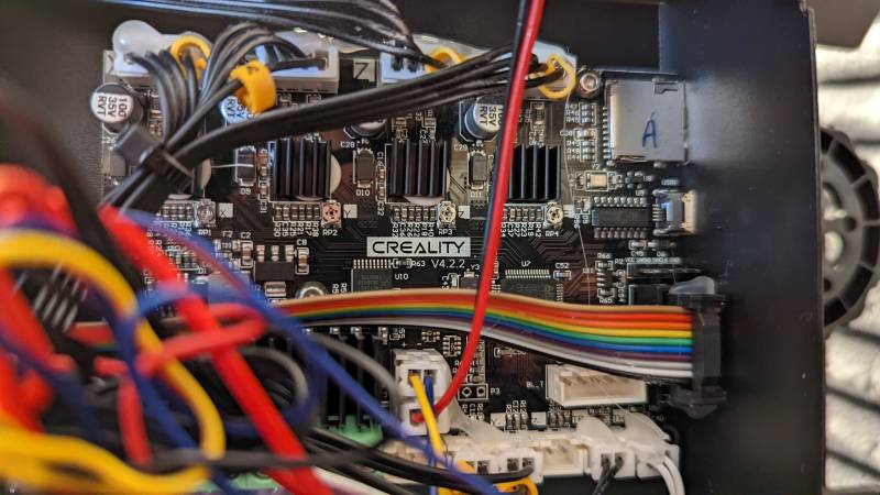
This week-end I took the time to add an automatic bed levelling system on my Ender 3 V2. I sadly haven’t have so much time to test it properly, but here are a video of the system working and a picture of the inside of the beast!
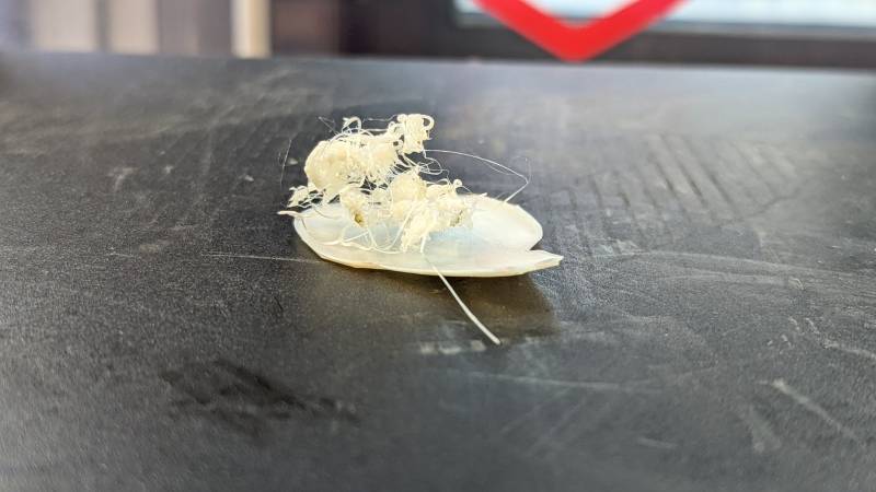
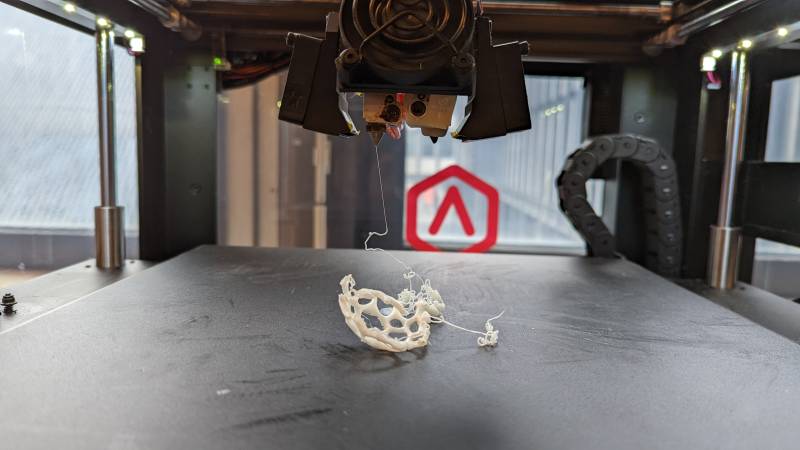
After installing the automatic bed levelling I made a first test print. It was not a successful print, too much stringing! I will try to update this page with the good calibration settings for the printer.
Resources
- Be aware of your 3D printer environment issues (paper)
- How to setup Octoprint for an Ender 3 V2 (for future reference)
Files
About this week
I was very happy about the scanner we have at the lab. Now that I know how good the results are, it opened some possibilities for the future, even if it’s only for small objects.
The resin printing experience was great: I never did that and I learned so much. I have access to these machines and intend to enjoy them and test them farther if I can.
As for the FDM printing experience, I enjoyed designing an object specifically for this purpose (and I love Blender even more), but I did not test as many as I wanted initially. What about flexible filaments, bicolor printing? I hope I will have the time to experiment with these before leaving the lab.
I will complete this week’s documentation with the best parameters I use with my Ender 3 at home. As I explain below, I didn’t have time to test everything after the automatic bed levelling addition.
I was asked to present my work during the weekly review: you can watch it here (at 0:26:14).
I try to keep up with the Instagram posts, but it’s not easy to summarize a all week in a tiny post!