Input Devices
- Measure something: add a sensor to a microcontroller board that you have designed and read it
- Probe an input device’s analog levels and digital signals
This week is all about measuring something from the real world and read its value on a computer. I love this idea as it begins to feel like creating my own embedded systems. I also want to try my best and catch up on the Output week that didn’t go as planned.
Generic board SAMD21E17

Thanks to AgriLab I could redo my SAMD21 board with a E17 version, which is proven to work, unlike the E15 we have at the lab.
The milling went without surprise as I kept my FlatCAM files ready to use. I just changed the text on the KiCAD file to indicate the right version.
The soldering part was as tricky as last time for the USB connector (I had to redo it three times to get it to work properly). I also encountered a problem with one of my USB cable that did not work. Thankfully Stephane had one that did the job and permitted me to work this week (but this kept me stuck all week-end, I will check my cables everytime from now).

The board was now complete and I could upload the appropriate bootloader without any issues.
ejoz@ejoz-xps-13:~/Desktop/DevKit-ATSAMD21E17A-U$ edbg -bpv -e -t samd21 -f sam_ba_SAMD21E17A.bin
Debugger: Alex Taradov Generic CMSIS-DAP Adapter 548B520D v0.1 (S)
Clock frequency: 16.0 MHz
Target: SAM D21E17A (Rev D)
Erasing... done.
Programming.... done.
Verification.... done.
To celebrate, I immediatly uploaded a blink example to test it. Thankfully, everything works as intended: what a relief!
One board to measure them all
I was so happy that my SAMD21E17 proto board were working, that I had the idea of making an Input board with as many inputs devices I could. I listed some that I wanted to try and I will try to design one this week-end. I want it to be pluggable directly on my proto board. I’m so excited ! I hope the routing won’t be too hard. If I fail I will make several tiny boards.
Input board
KiCAD design
I want to include several input devices that could be of use in my final project. I will also add a RGB led to the board to simulate light outputs.
Input devices to include
- Gesture and color sensor via I2C (we have the APDS 9960 at the lab and it will be fun to test it)
- Button (simple but effective)
- Phototransistor and thermistor to study analog inputs
- Microphone (just for testing purposes, but maybe it will be of help for a speech recognition application in the future ?)
Pins and I2C
First I added the pins of my generic board: I want to connect the input board directly to it. I will use female connectors to plug it in. I also added some pins to connect the gesture sensor via I2C.

Thermistor and phototransistor
I then studied the thermistor and phototransistor schematics: we have to use a voltage divider to connect them, and I read from Adrian’s documentation that 10K is a standard value for this type of sensors.

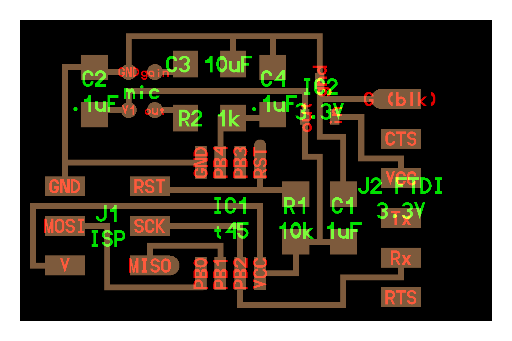
MEMS microphone
I then added the microphone: it was the trickiest part. I first read the datasheet and tried to reproduce the schematics according to the interface circuit diagram. As I wasn’t sure of my doing, I checked Neil’s version for confirmation. As it turned out, Neil’s schematics is slightly different from the datasheet. To be sure, I took Neil as a reference and based my schematic on his board.

Button and RGB led
Then I added a simple button and a RGB led as I did previously for my first board (it seems like months away).


Routing
Finally I routed everything. I must say it feels good to do it rather quickly now instead of very slow a few weeks ago.

Fabrication
Milling
Same as for the design, the fabrication is quite straightforward now I’m comfortable with the SRM20. I entered the usual parameters in FlatCAM and the milling went well. It took around 20 minutes for the tracks isolation, around 30 minutes for removing the copper, and less than a minute for the cutout.

As a reminder, here are the parameters I used for the SRM 20. I may use 40% offset from now on as Stephane told me it worked well.
| Tool diameter | Depth | Feedrate X/Y | Feedrate Z | Spindle | Offset | |
|---|---|---|---|---|---|---|
| Isolation | 0.2 | -0.06 | 80 | 100 | 8000 | 50% |
| NCC | 0.8 | -0.05 | 80 | 100 | 8000 | |
| Cutout | 2 | -1.9 (0.95*2) | 80 | 100 | 8000 |
Soldering


I soldered everything without too much trouble: it changed from the SAMD with its really tiny pins and from the devilish USB port. The microphone only was a little tricky, as it need to be soldered with the hot air gun only. As it’s impossible to check underneath it after fixing it, I don’t know if it worked well. We’ll see when testing…
I was also careful to lower the temperature of the solder iron when fixing the WS2812 as it’s super sensitive.
I came up with a pretty cool solution to not waste time checking the polarity of my components every minute or so, and to save my computer for suffering from my clumsiness. First I dispose every components on the board and check once the polarity. Then I take a picture to keep in mind the disposition of the components and dispose them on the plate in the same way. After that I can solder without having to check and I keep my computer far away from the soldering station.
Programming
And now the fun begins! I of course made several mistakes, but thankfully I was able to fix them one by one.
My first mistake was to not have been careful with the APDS: I planned to include it on the board and left place for it when routing, but I inversed the order of the pins. So it wasn’t possible to solder it directly on the board: I put female conectors instead, but it’s not as integrated as I wanted to be. It looks pretty good otherwise, I’m super happy with this design so far!

Alas… The second big mistake I made was not to check the pinout when designing. The first time I plugged my board, I didn’t understood why I wasn’t able to read an analog signal form the thermistor and phototransistor. It turns out I plugged them in pins that aren’t able to read analog inputs! Believe me, I cursed myself for that mistake.
Thankfully I’m able to plug the board on the analog pins that are free on the SAMD21. I got lucky, because now I can have analog reading or digital readings at will.

As a reminder for me, here is the pinout for the SAMD21. I will not make that mistake again (or at least, I will be able to tell myself I told me so).
============================= MattairTech MT-D21E (ATsamD21EXXA) ========================
Other  COM    PWM   Analog  INT  Arduino*             Arduino*  INT   PWM     COM   Other
=========================================================================================
                                      -------------------
Xin32                                | A0            RST |                           BOOT
Xout32                               | A1            NC  |
DAC                   *            2 | A2            NC  |
REFA                  *            3 | A3            A31 | 31    *   TCC11   RX3   SWDIO*
REFB                  *      *     4 | A4            A30 | 30    *   TCC10   TX3   SWDCLK
                      *      *     5 | A5            NC  |
                      *            6 | A6            A28 | 28    *                   LED
VM                    *            7 | A7            A27 | 27    *                   BTNA
  SDA1/MISO1  TCC00   *     NMI    8 | A8            A23 | 23    *   TC41     SS
   SCL1/SS1   TCC01   *      *     9 | A9            A22 | 22    *   TC40     MISO
      TX1     TCC02   *           10 | A10           A19 | 19    *            SCK
      RX1     TCC03   *           11 | A11           A18 | 18    *            MOSI
   TX2/MOSI1   TC30          *    14 | A14           A17 | 17    *   TCC21    SCL/RX4
    RX2/SCK1   TC31               15 | A15           A16 | 16    *   TCC20    SDA/TX4
                                     | NC            NC  |
                                     | NC            NC  |
                                     | Vbus          3.3V|   * Button B available on 31.
USB D-       TC50                    | A24-  _____   Vcc |
USB D+       TC51                    | A25+ |     |  Vin |
                                     | Gnd  | USB |  Gnd |
                                      -------------------
Arduino tips
I found out this week that we could listen to Serial port directly from the terminal. I can see it will be helpful when programming interfaces.
I also used a lot the map() function to read the analog input correctly. You can find the references on the arduino website.
And finally, I discovered the Serial Plotter! I used Arduino for a long time now and I never knew this was as simple as the Serial Monitor: I feel stupid and happy at the same time.
I also found out that Arduino is releasing a 2.0 version of its IDE. I can’t wait to test it!
Gesture and color sensor
To use it, I have to plug the Input Board in Digital Mode, or add some wires.

When plugging the sensor for the first time, I wasn’t able to detect anything from the example codes. So I uploaded an I2C scanner code to check if the device was recognized.
It worked and detected the device.
But when uploading the example code from the Adafruit library it didn’t work. So I tested the sensor on my Arduino Nano: works like a charm. I retested it with my board and get discouraged.... So I went to fetch another I2C device in our electronics drawers. As I came back to my computer, I waved an au revoir to the sensor, and in my greatest surprise it worked! The gesture example detected my hand. I restested several configurations and it turns out the sensor takes around one minute to react.
I tested the color detector code, and this one works instantly.... More and more weird. I found a very interesting forum article from a person who had the same problem. I tried to resolve using these advice without success. After that, I tried again and found out that it takes less time than before. As I couldn’t figure out why the behaviour was unconsistant, I decided to move on and avoid the rabbit hole for this week.
I had fun reading about this sensor and testing several behaviour. It turns out the color sensor is quite tricky to trigger because when you approach an object from it, it gets dark and has trouble recognizing the color.

Button and ButtonStates library
During machine week, Stephane showed me his own ButtonStates library he wrote to avoid debouncing and detect single clicks, double clicks as well as long clicks. It’s really useful for some use case and I had fun with it.
  int clicks = button.triggerLong();
  switch(clicks) {
    case 1:
      lightPixel(0,127,0);
      break;
    case 2:
      clearPixel();
      break;
  }
RGB Leds
As I want to use heavily RGB leds in my final project I started to test several functions for them. I want to write eventually an effect library for my final project. For now I just simplified their uses.
void lightPixel(int r, int g, int b) {
  pixels.fill(pixels.Color(r, g, b));
  pixels.show();
}

void clearPixel() {
  pixels.fill(pixels.Color(0,0,0));
  pixels.show();
}

void blinkPixel(int r, int g, int b) {
  lightPixel(r, g, b);
  delay(500);
  clearPixel();
  delay(500);
}
Thermistor NTC 1206 10K ohm
Thanks to Lucio Pentagna I found this link that explained to me how to get a proper value from a thermistor with the Steinhart-Hart equation.
float temperature() {
  // From https://circuitdigest.com/microcontroller-projects/arduino-thermistor-interfacing-code-circuit
  float vOut;
  float A = 1.009249522e-03, B = 2.378405444e-04, C = 2.019202697e-07;
  float tempKelvin, logRt, tempCelsius, tempFarhenheit;

  vOut = analogRead(thermistorPin);
  logRt = log(10000.0 * ((1024.0 / vOut - 1)));
  tempKelvin = (1.0 / (A + B * logRt + C * logRt * logRt * logRt));
  tempCelsius = tempKelvin - 273.15;
//  tempFarhenheit = (tempCelsius * 1.8) + 32.0;

  return tempCelsius;
}
Phototransistor
Sparkfun made several articles about reading sensors values, including one on phototransistors. Mine struggles to detect small variations of luminosity, I had to approach a light very closely to detect a change in values.
int luminosity() {
  int lum;
  lum = analogRead(phototransistorPin);
  lum = map(lum, 0, 1024, 255, 0);
  return lum;
}
Microphone
I found this useful article about the MEMS microphone and was able to read the signal from it easily.
int mems() {
  int micOut;
  micOut = analogRead(microPin);
  return micOut;
}

void memsPlotter(int micOut) {
  Serial.println(micOut);
  delay(50);
}

Serial monitoring
I put together all the values of my Input board. I will be able to experiment with these various components now. I can even plug other digital outputs to my SAMD21 to react from the input received without having to redo a board.

Probing an input with the oscilloscope

To measure something and be more precise than with the Serial Monitor or than the Logic Analyzer, we can use an oscilloscope to determine the tension of an input device. We tested the thermistor by plugging it to our lab oscilloscope: we have to connect the mass and the thermistor pin (4 in our case).

Once it was plugged in, we tested it by heating the thermistor: it was immediatly noticable on the screen.

You can see everything on the video below: how we heat the thermistor and see at the same time the variation on the screen.
Files
About this week
I enjoyed this week really much, it was fun to test input devices in the lab. I am happy to see that I’m now able to design a board quickly, to fail doing it, and to correct my mistakes right away. I’m starting to feel the prototyping joy!
I tested the newest Arduino IDE on Wednesday morning, it’s really cool!
