Input Devices
Overview
This section covers the design and implementation of input devices, focusing on sensor integration and microcontroller programming as part of the Fab Academy 2020 project by Lucio Pentagna.
Group Project
- Measure the analog levels and digital signals in an input device.
Individual Project
- Measure something: add a sensor to a micro-controller board that you have designed and read it.
Learning Outcomes
- Demonstrate workflows used in circuit board design and fabrication.
- Implement and interpret programming protocols.
Have you:
- Described your design and fabrication process using words/images/screen-shots.
- Explained the programming process/es you used and how the micro-controller data sheet helped you.
- Explained problems and how you fixed them.
- Included original design files and code.
Week Workflow
Study Neil's input boards → Decide what type of input → Design Schematic/Board → Mill the board → Solder components → Debug → Edit and publish website
Tools Used
- Solder Station
- TaoBao CNC
- Test equipment: digital voltmeter, oscilloscope, regulated power supply
Software Used
- Autodesk Eagle
- PCB-Gcode ULP for Autodesk Eagle
- Auto Leveller
- Fab Modules
- Gimp
Files
Group Assignment
Visit the group assignment page for more details.
Individual Project
This week, I focused on testing a thermistor, which is essential for my incubator project to measure and control temperature.
The thermistor I chose is the B57560G0104. According to its datasheet, it has a resistance of 100K at 25 degrees Celsius.
The thermistor's resistance decreases as the temperature increases. Since the IC on its ADC pin reads voltage, not resistance, a voltage divider is necessary to derive its resistance.
I connected the thermistor in series with a resistor to VCC. One end of the thermistor is connected to ground, and the other is in series.
References
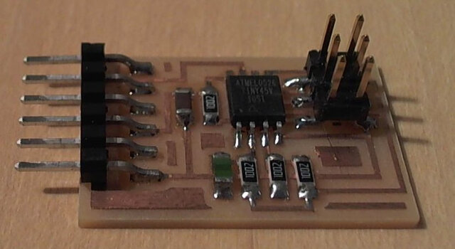
As done in week 6, I started by reviewing Neil's boards. The one I redesigned is the visible light input board.
Experimenting with an Arduino
The goal of this experiment was to understand and test the thermistor and the code. Although I got it working, the temperature readings were not very accurate. Without precise instruments for calibration, I boiled water to ensure the temperature was around 100 degrees Celsius.
Programming the Attiny with a USBasp
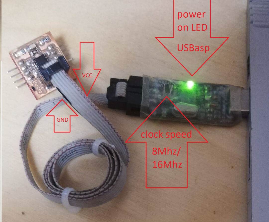 Programmer USBasp on a ATtiny45
The video below demonstrates the programming process.
Experiment with the Board I Designed
Designing the PCB
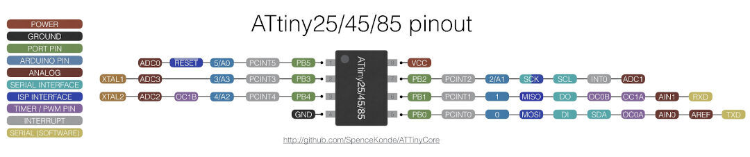
Because I normally program with Arduino IDE it's quite useful to have not only the data-sheet but also a diagram that converts the pins from one programming platform to the other.
On a quick look, we can determine that there are 4 Arduino analog pins. They all have an analog to digital converter (ADC0, ADC1 ADC2, ADC3), so they could also be used as digital pins together with pins 1, 0, and 2.
For this assignment, I will need 1 analog pin and 2 digital pins. The analog pin I will connect the thermistor and the digital pins are for the serial communication.
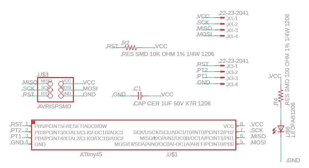
The board will have a header for the ISP programmer, 2 headers on the sides so all pins can be used and tested as needed as well as a led just to show there is power coming in.
Autodesk Eagle is the weapon of choice. but I will be creating the G-code with pcb-gcode addin.
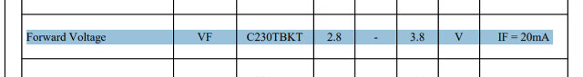
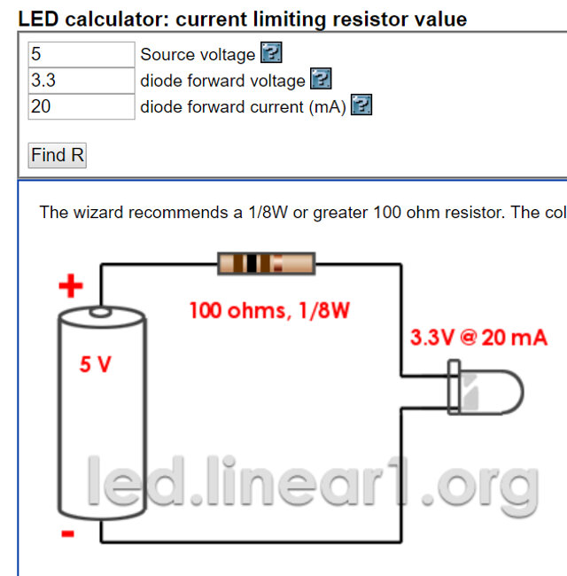
Resistor calculations
In order to calculate the resistor values, I examined the following Datasheets and the calculations/observations I made:
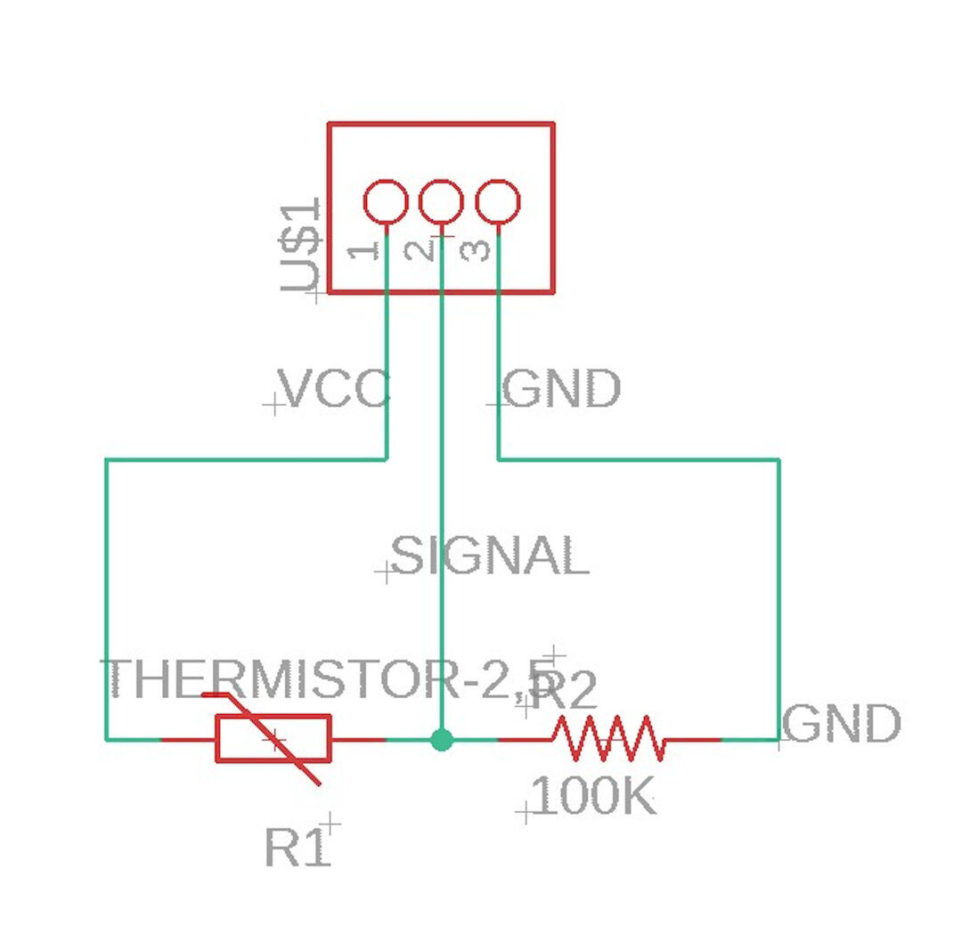
Below is the schematic of my design:
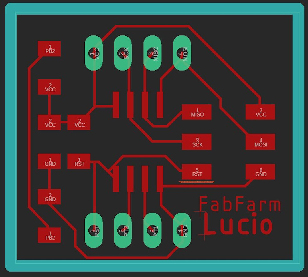
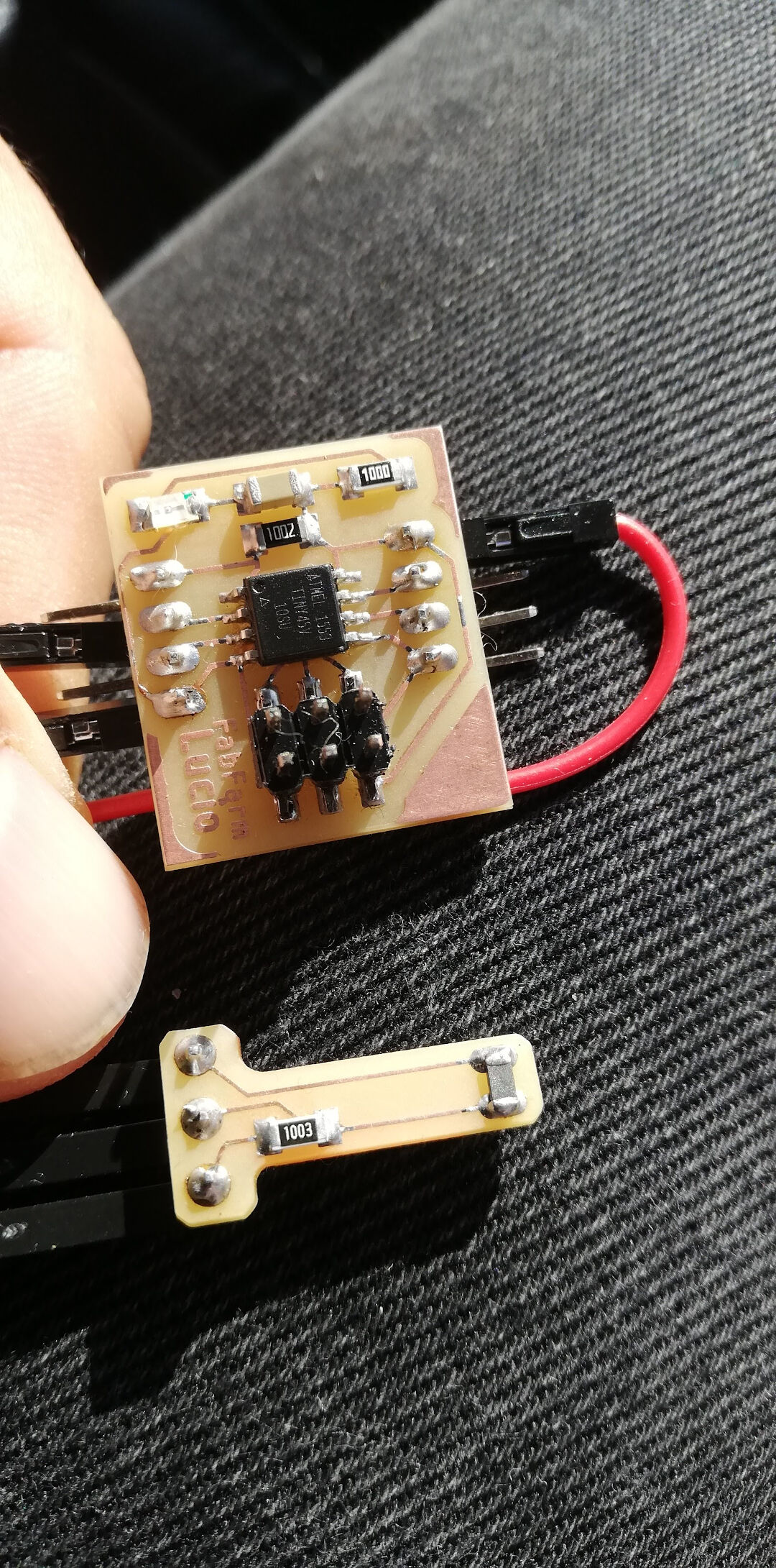
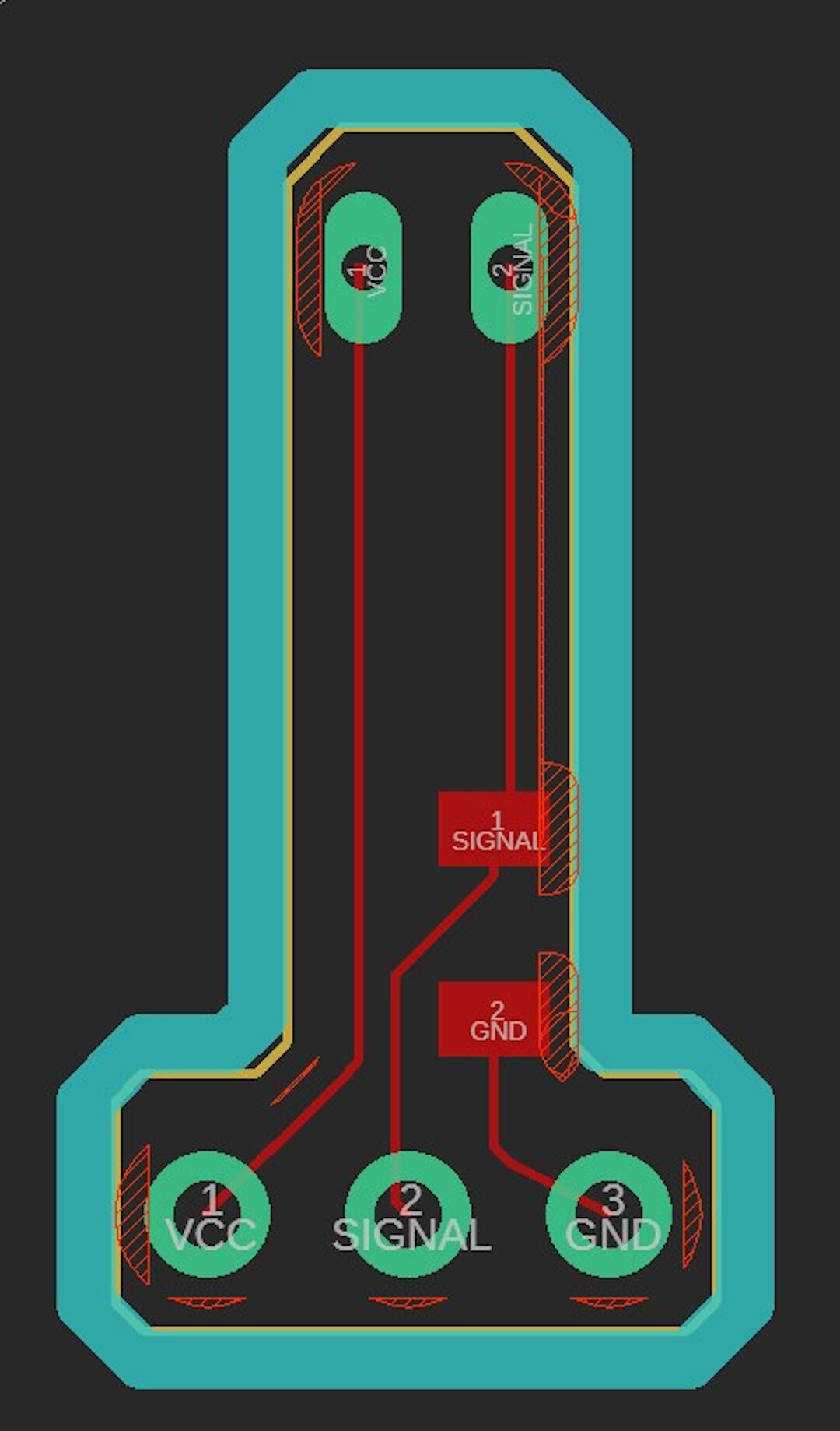
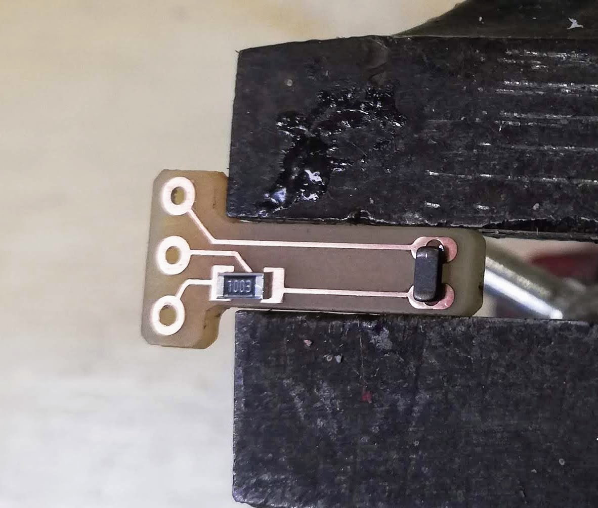
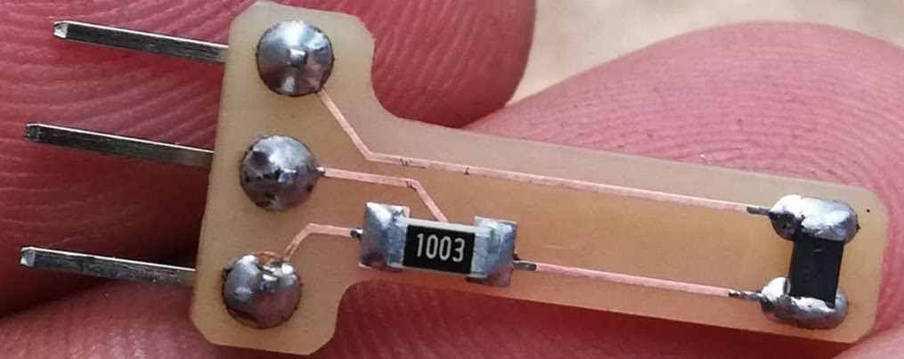
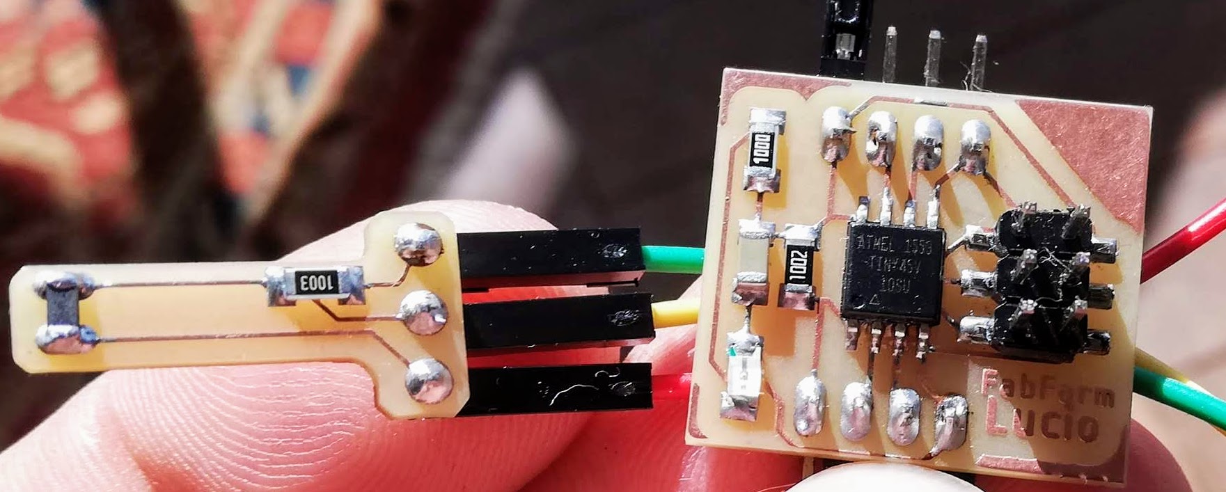
The Thermistor Board
On my thermistor board, I used:
- Vishay Dale NTHS1206N01N1003KE NTC 100KOHM 3964K 1206, datasheet here.
- A 100k resistor as a pull-down resistor
An NTC thermistor's resistance decreases as the temperature increases, and vice-versa. To calculate the resistance, a known resistor is used to measure the voltage drop. The ATtiny45 doesn't measure resistance directly, so the formula used in the program is: RT = ((VCC*R-R*VRT)/VRT)
Code for the Attiny45
I used three sets of code for this assignment:
- Software serial sources: source1 source2
- Temperature collection with Arduino
- My version of the code includes both the software serial and part of Marcazzan's code, as the attiny wouldn't compile with both the software serial and the log calculations. The code had to be limited to only 4k after compilation.
Since regular hardware serial couldn't be used on the attiny, a library was included to enable this function:
#include "SoftwareSerial.h"
SoftwareSerial Monitor(1, 0);

void setup()
{
    Monitor.begin(9600);
    pinMode(0, OUTPUT);
    pinMode(1, INPUT);
}
Printing is done differently:
Monitor.println(whatever you want to print here);
The code used for Arduino experiments was found on the Arduino's project hub How Easy Is It to Use a Thermistor?! by Marcazzan_M:
//Thermometer with thermistor

/*thermistor parameters:
 * RT0: 10 000 Ω
 * B: 3977 K +- 0.75%
 * T0:  25 C
 * +- 5%
 */

//These values are in the datasheet
#define RT0 10000   // Ω
#define B 3977      // K
//--------------------------------------

#define VCC 5    //Supply voltage
#define R 10000  //R=10KΩ

//Variables
float RT, VR, ln, TX, T0, VRT;

void setup() {
  Serial.begin(9600);
  T0 = 25 + 273.15;                 //Temperature T0 from datasheet, conversion from Celsius to kelvin
}

void loop() {
  VRT = analogRead(A0);              //Acquisition analog value of VRT
  VRT = (5.00 / 1023.00) * VRT;      //Conversion to voltage
  VR = VCC - VRT;
  RT = VRT / (VR / R);               //Resistance of RT

  ln = log(RT / RT0);
  TX = (1 / ((ln / B) + (1 / T0))); //Temperature from thermistor

  TX = TX - 273.15;                 //Conversion to Celsius

  Serial.print("Temperature:");
  Serial.print("\t");
  Serial.print(TX);
  Serial.print("C\t\t");
  Serial.print(TX + 273.15);        //Conversion to Kelvin
  Serial.print("K\t\t");
  Serial.print((TX * 1.8) + 32);    //Conversion to Fahrenheit
  Serial.println("F");
  delay(500);
}
The code here
#include "SoftwareSerial.h"
#define VCC 5    //Supply voltage
#define R 100000  //R=100KΩ

float RT,VRT,VR;

SoftwareSerial Monitor(1, 0);

void setup() {
    Monitor.begin(9600);
    pinMode(0, OUTPUT);
    pinMode(1, INPUT);
}

void loop() {
    VRT = analogRead(3);              //Acquisition analog value of VRT
    VRT = (5.00 / 1023.00) * VRT;      //Conversion to voltage
    VR = VCC - VRT;
    RT = ((VCC*R-R*VRT)/VRT);               //Resistance of RT

    // Monitor.println("Voltage Read:");
    // Monitor.print(VRT,10);
    // Monitor.println("Voltage drop:");
    // Monitor.print(VR,10);
    Monitor.print("Resistance:");
    Monitor.println(RT);

    delay(1000);
}
The original formula for finding the resistance didn't work for me, likely due to using an NTC thermistor. I modified the formula to:
RT = ((VCC*R-R*VRT)/VRT); //Resistance of RT
Designing and Making the PCB
After modifying my workflow, I updated it to include the usage of PCB-Gcode ULP and Autoleveller software.
Autodesk Eagle Design
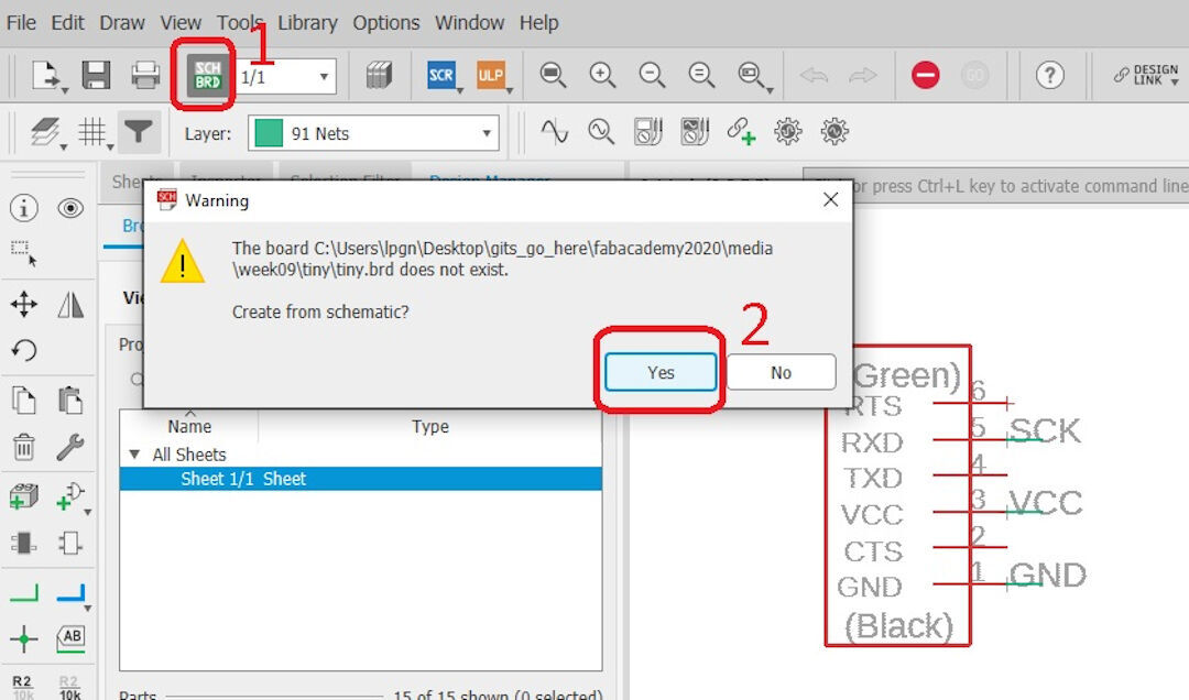
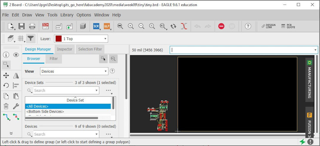
With the schematics ready, follow these steps:
- Click SCH/BRD to open a dialog.
- In the dialog, click yes to place the components next to the board space.
With the components placed next to the square representing the board, the board will be resized later.
Type "move" and press enter to click on each component and drag it inside the board.
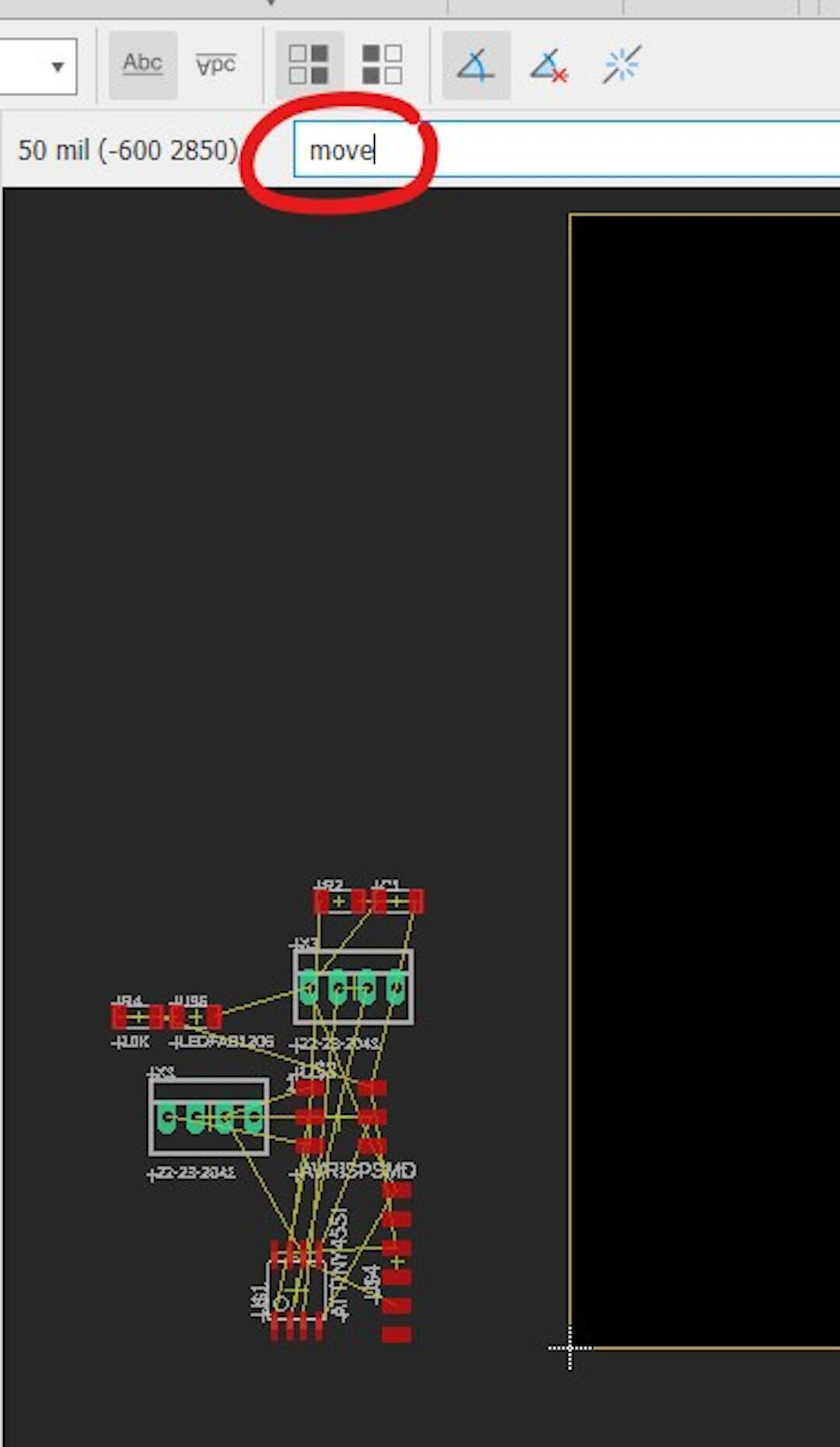
Here, I started dragging the attiny45 inside the board limits. Clicking each component won't require typing "move" again unless "esc" is pressed or another command is used.
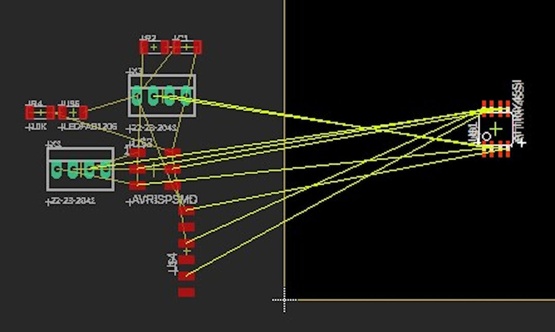
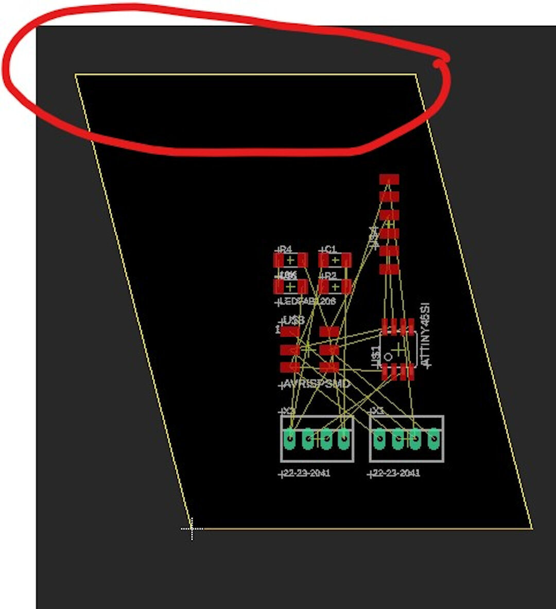
All components are dragged, and the superior limits are being dragged and resized with the "move" command. Another way to move components is by typing "info" and then left-clicking the component, allowing you to type the coordinates of the element instead of dragging.
The "rotate" command allows you to turn the component to the ideal orientation for efficient wire routing. The yellow lines represent the connections created in the schematics part.
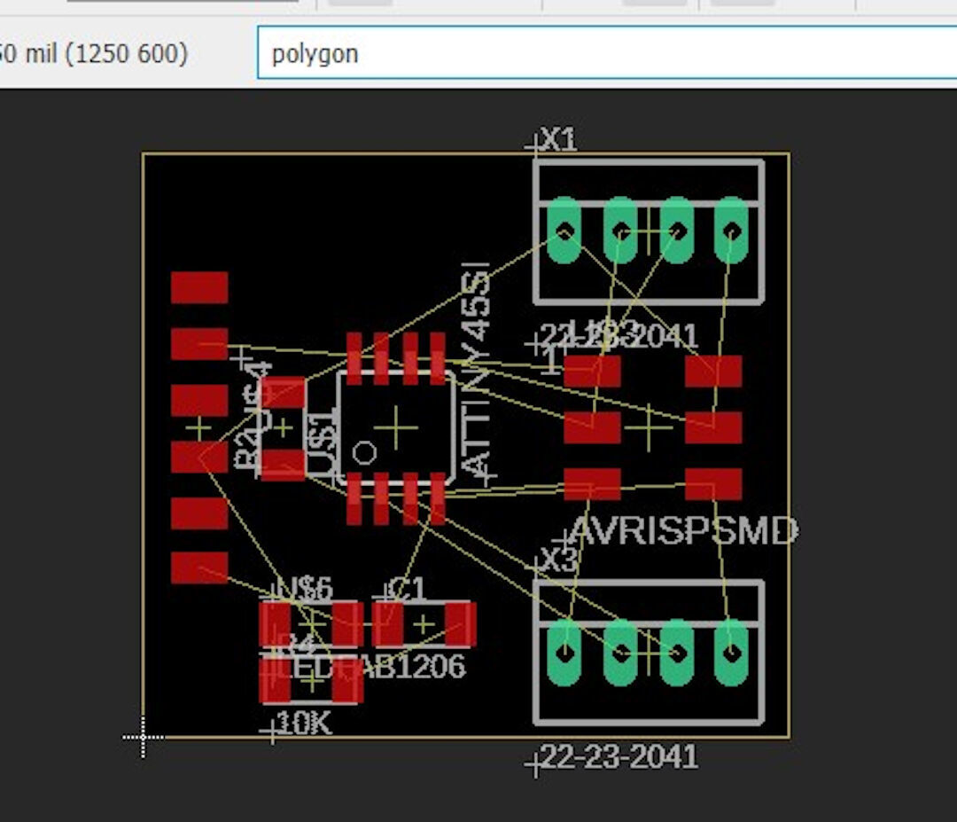
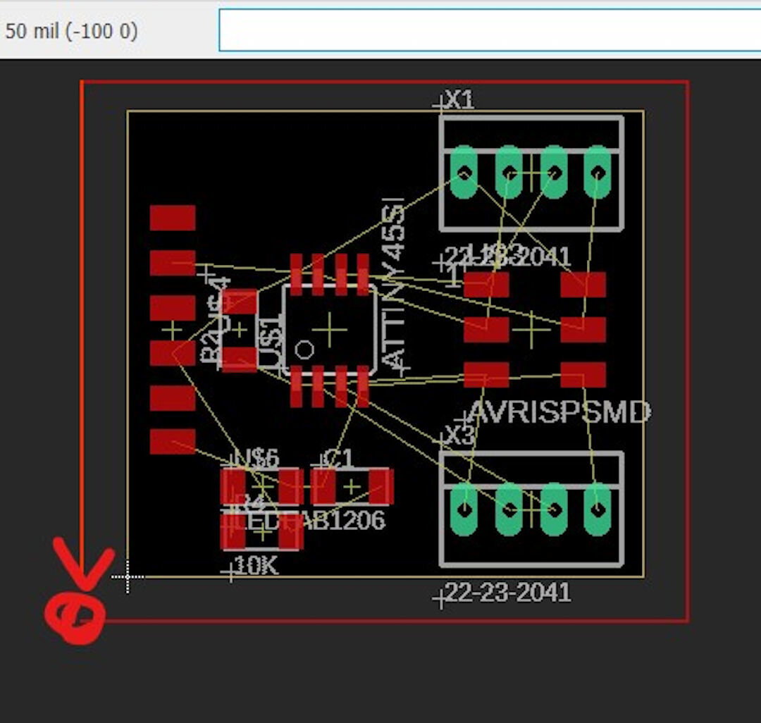
Here, I am creating a contour with the "polygon" command. When it's closed, a dialog box will open.
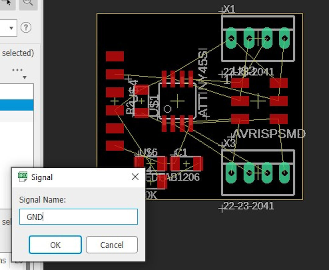
After the polygon is finished, the dialog will open. Typing "GND" connects the polygon to ground.
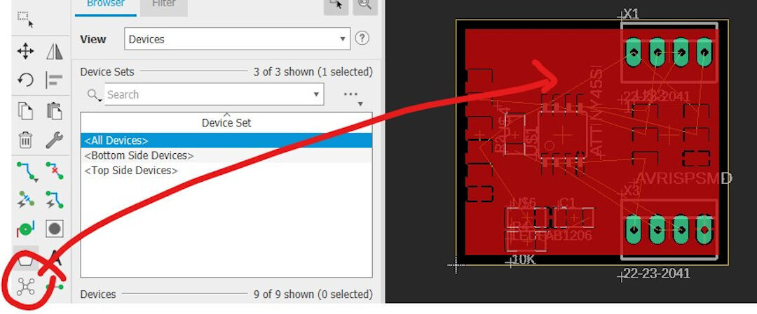
Typing "ratsnest" or clicking its icon will fill up the whole board area with the ground layer. Now, either by typing "autoroute" or using the "net" command, the components can be connected.
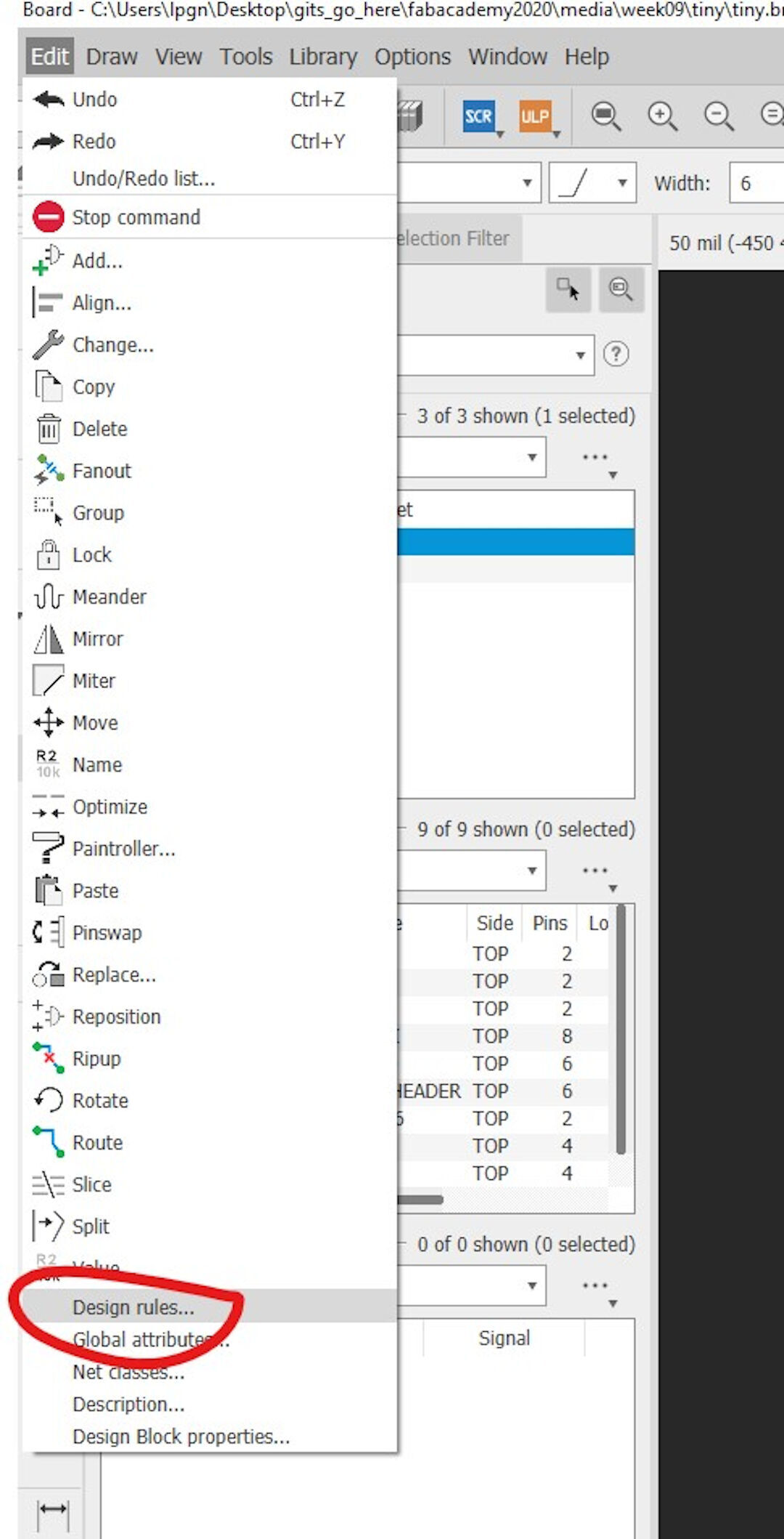
Before routing the components, go to edit → design rules to define the distances between each element.
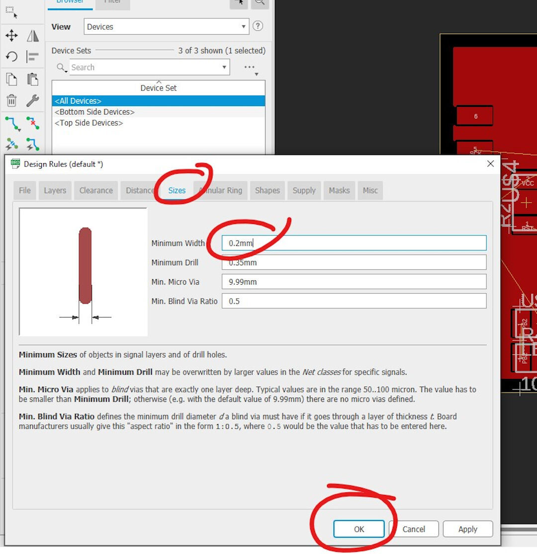
In the "sizes" tab, define the minimum width of the wire. In my experience, 0.2mm works great.
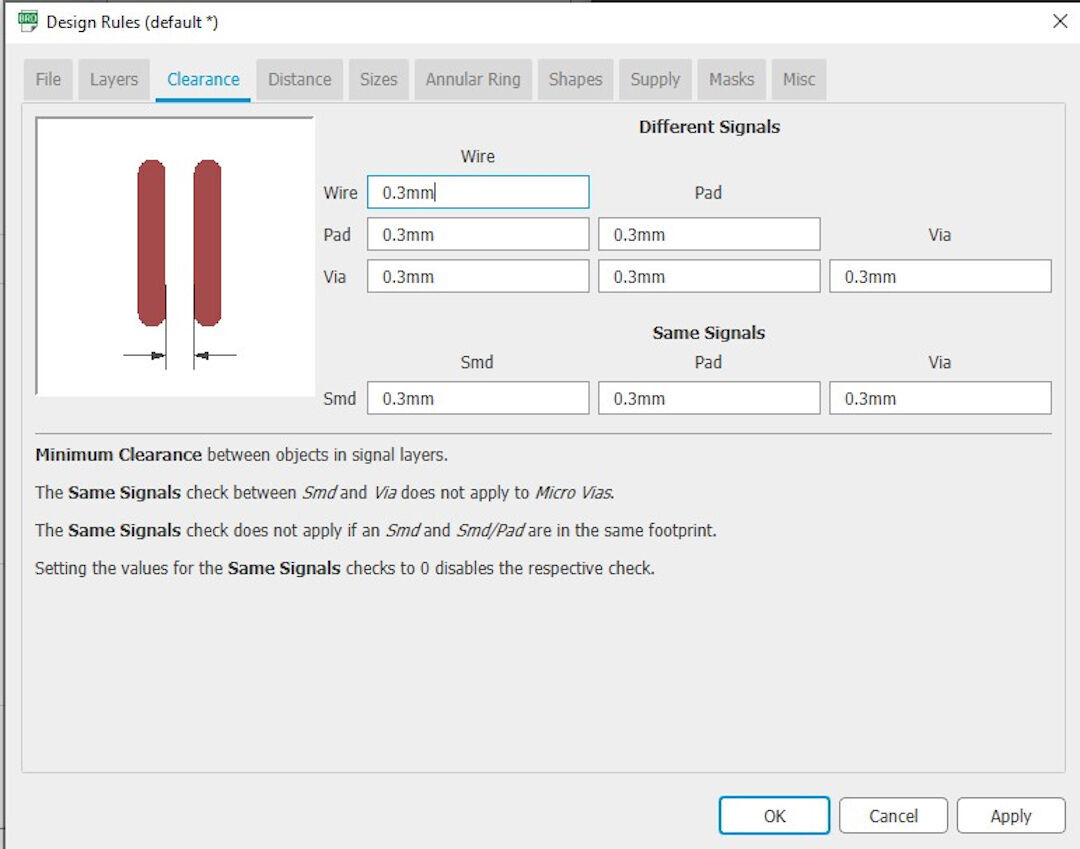
The "clearance" tab sets the distance between each element of the PCB. I am currently using 0.3mm on all signals.
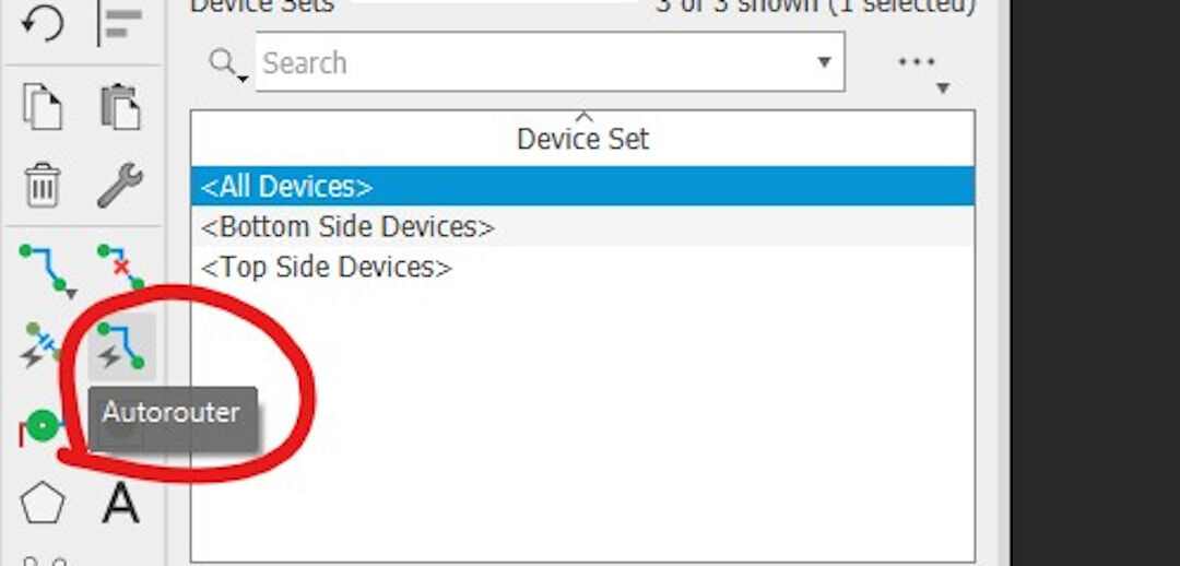
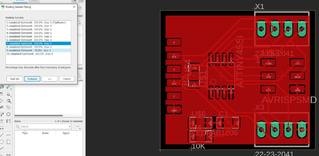
With all design rules set, typing "autorouter" or clicking its icon will start the process of connecting each component.
An important setting is clicking on the dialog box labeled "bottom" and selecting N/A if two sides are not desired. Then pressing will start the process.
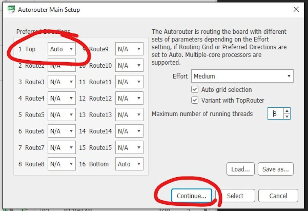
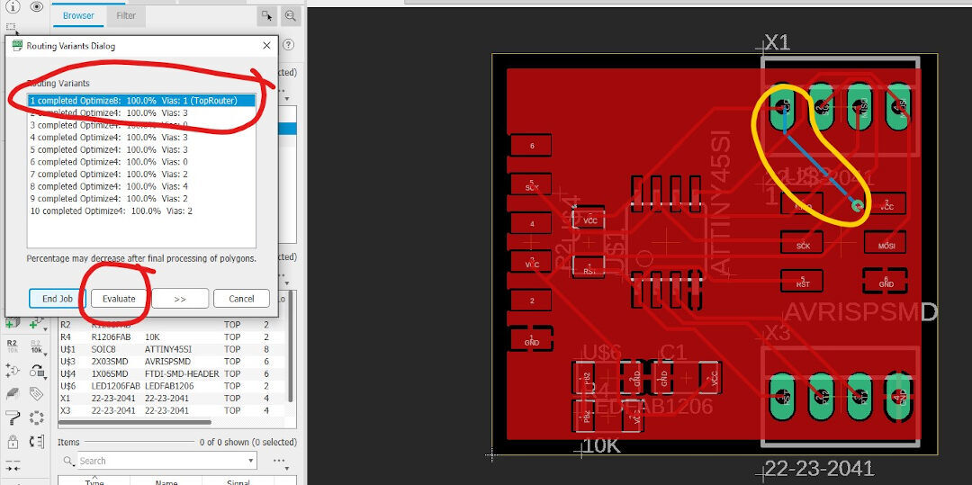
Next, choose one of the options and then click on "evaluate" or "end job" to return to the board layout.
I circled in yellow to show the bottom layer of the board in blue. I do not want this, so I will reset the board in the next step.
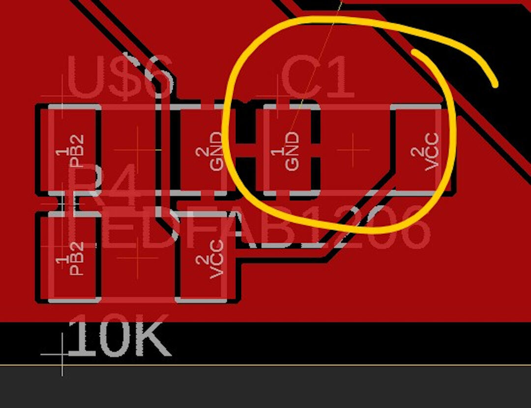
Here, you can see the effect of the "ratsnest" command. This command fills up all the spaces not occupied by a via with the ground element.
Because I want the autorouter to do it over, I typed "ripup" and then selected all so all routes are undone.
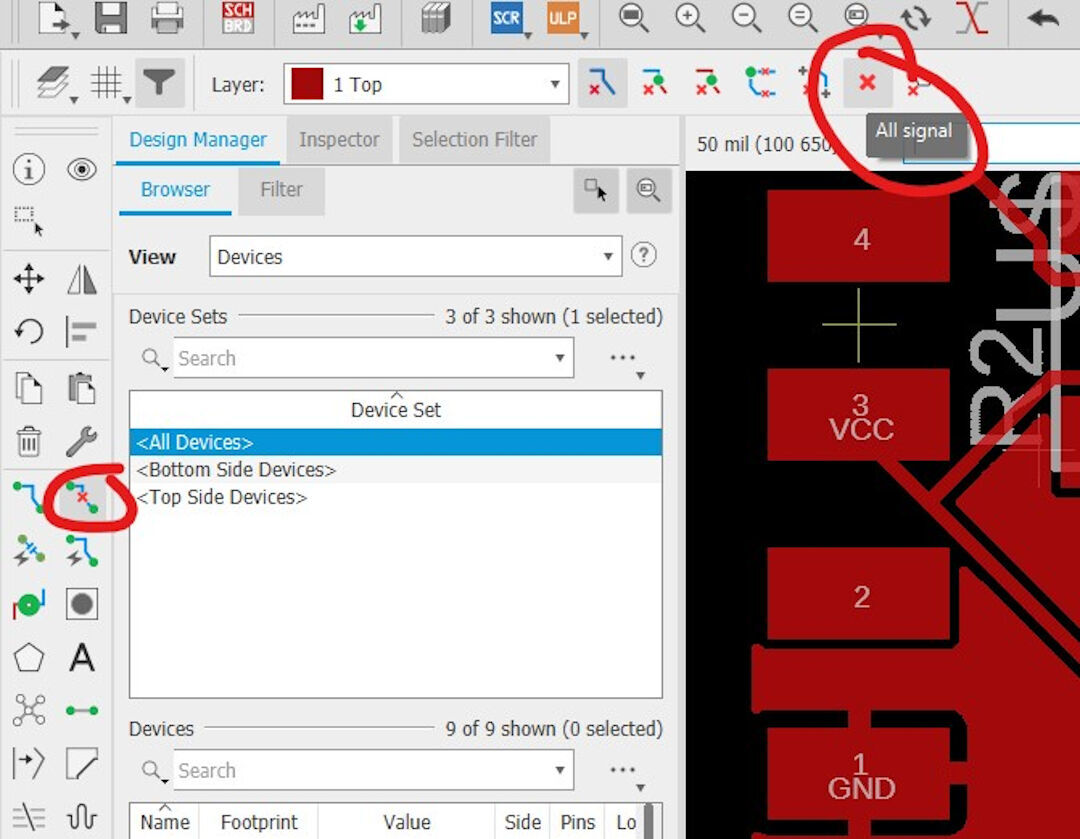
And redo the autoroute process.
Here, the route is done but not yet with "ratsnest".
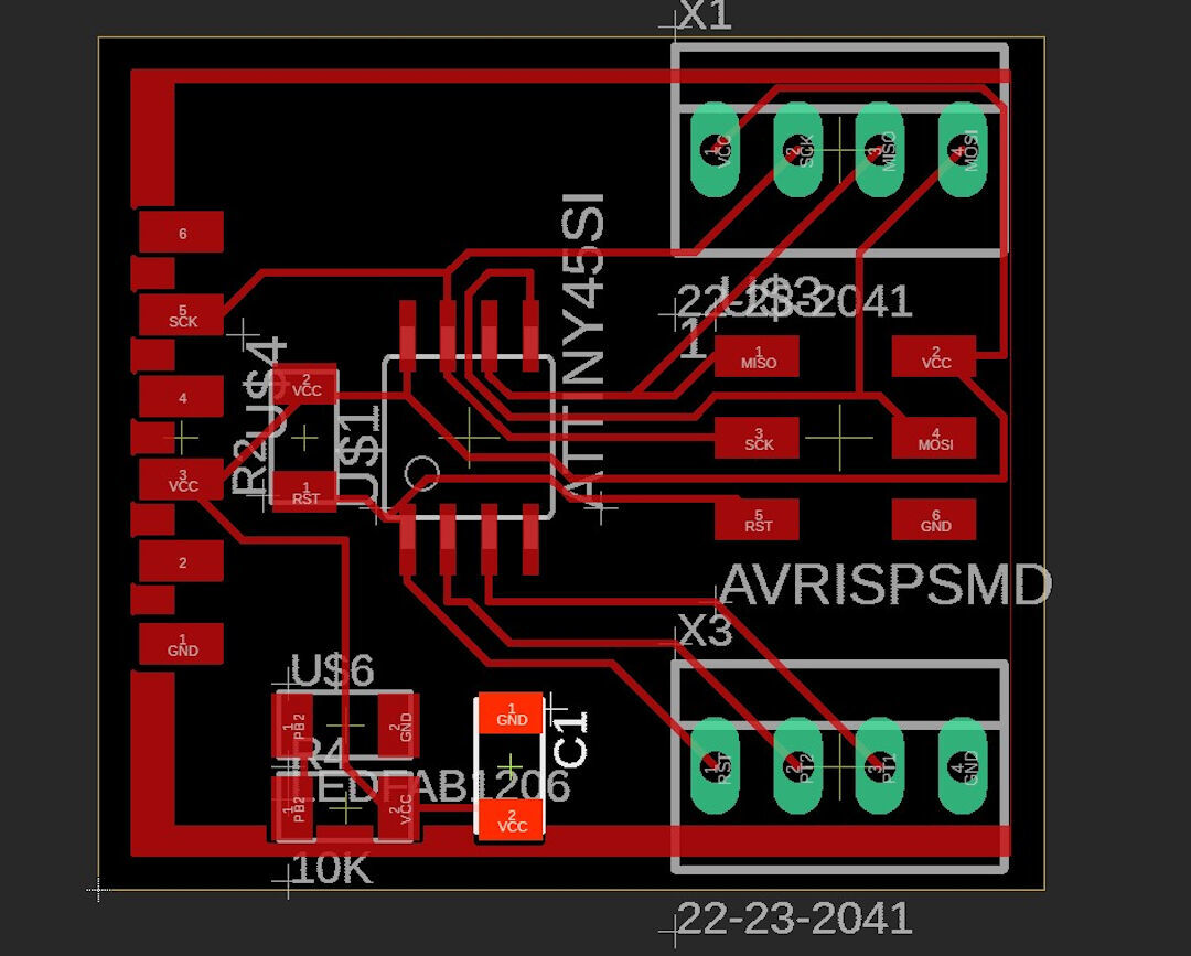
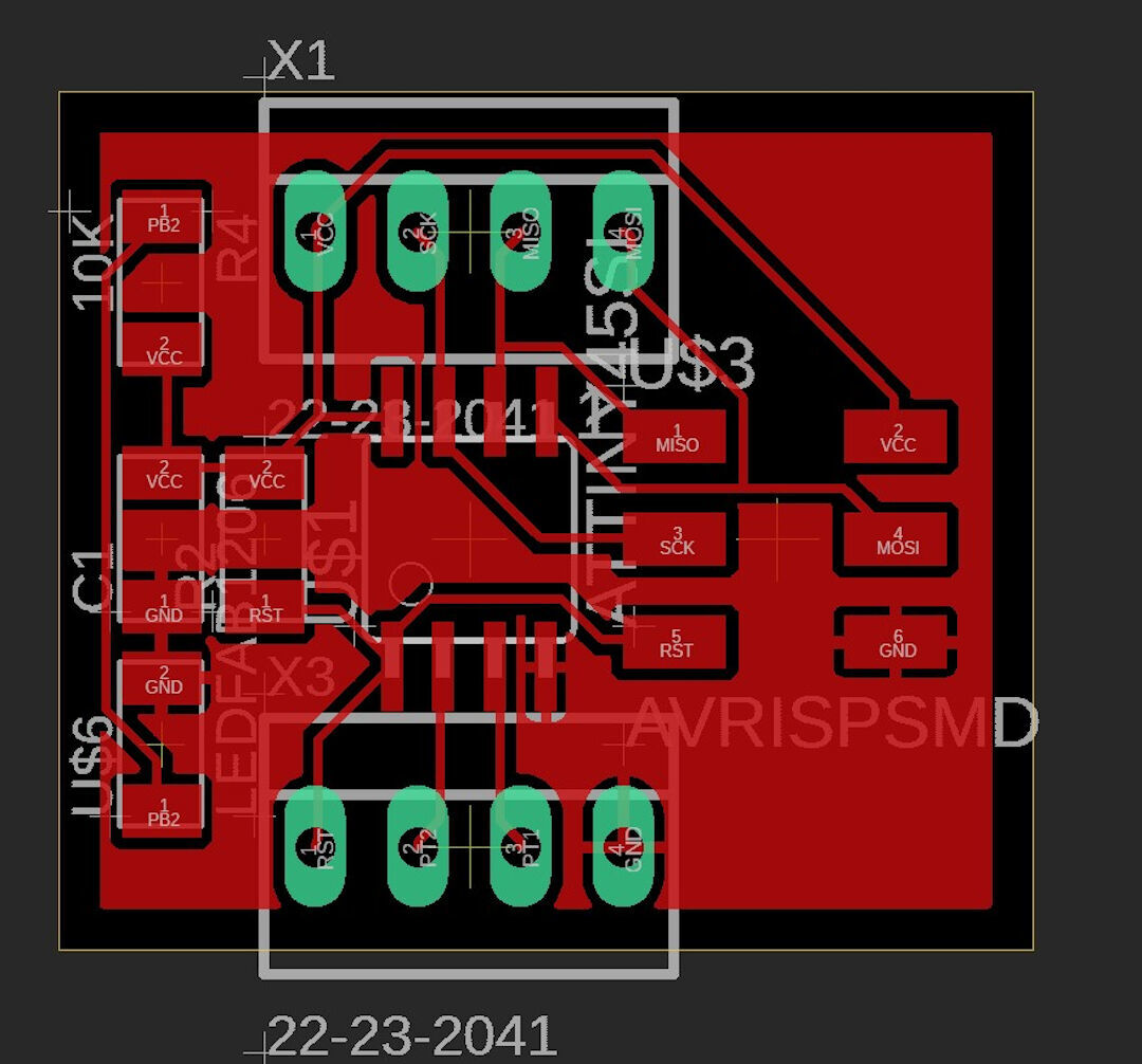
Here, "ratsnest" is applied.
In this step, I moved the components around to shrink the board a bit. This is done with the "move" command. If you want to move numerous components, select them and type "group", then type "move" and right-click them to move the whole group.
Ratsnest Dilemma
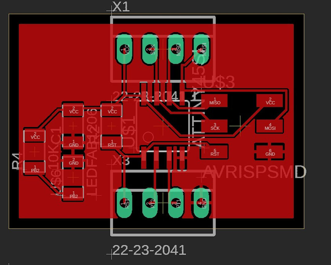
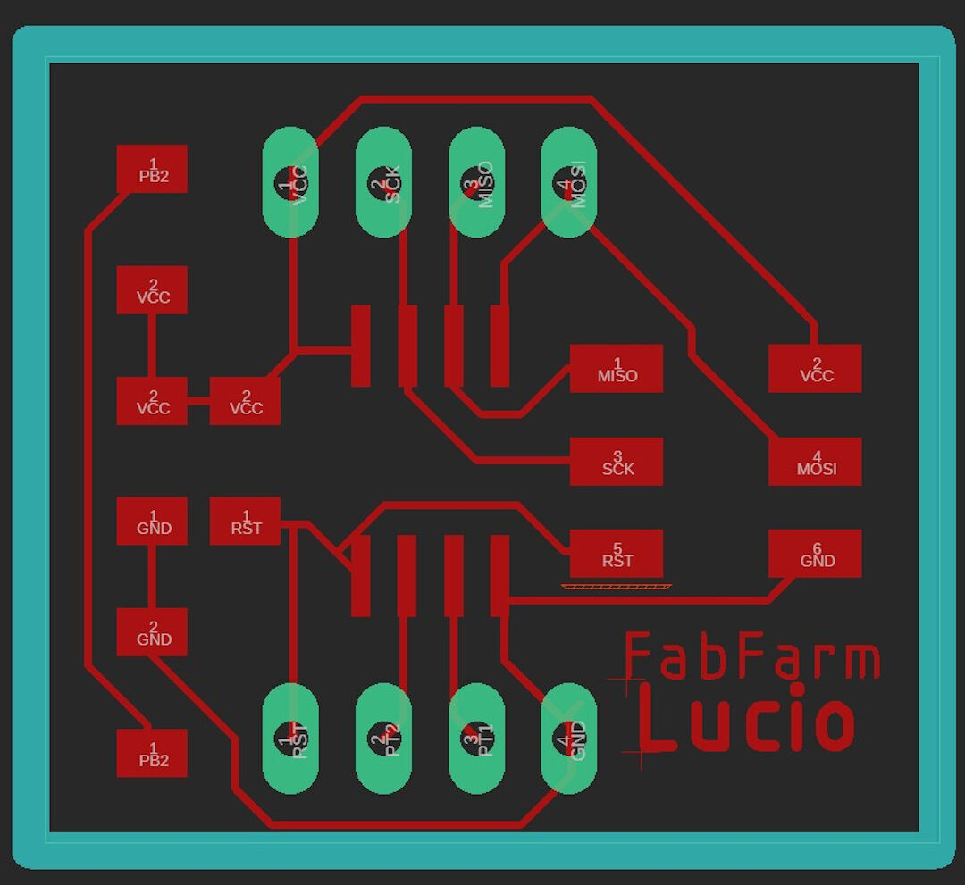
Below, you can see a board with and without "ratsnest".
The first board has "ratsnest" on. It's a bit more cluttered. One advantage is thermal, having a greater copper surface allows for cooling of the board as well as larger conductivity, especially in 2-sided boards where one side can be ground and the other side can be for VCC, making almost all surfaces for power transfer. The second board looks cleaner.
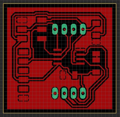
I currently prefer making boards without "ratsnest" because manual soldering can be imprecise, and short circuits are easy to happen, and the "ratsnest" feature can increase that risk.
The thick light blue contour drawn with the layer "milling" is used by the ULP pcb-gcode to create a G-code milling contour. The software will use that to create the limits, and the cut can be used to detach the board from the copper stock. The thickness of the polygon will define the milling bit size.
Board BOM
| qty | Location | Digikey or Mouser Part number | Manufacture Part # | Description |
|---|---|---|---|---|
| 1 | U1 | ATTINY45V-10SU-ND | ATTINY45V-10SUR | IC MCU 8BIT 4KB FLASH 8SOIC |
| 2 | R1 | 311-10.0KFRCT-ND | RC1206FR-0710KL | RES SMD 10K OHM 1% 1/4W 1206 |
| 1 | R2 | 311-100FRCT-ND | RC1206FR-07100RL | RES SMD 100 OHM 1% 1/4W 1206 |
| 1 | D3 | 160-1169-1-ND | LTST-C150GKT | LED GREEN CLEAR 1206 SMD |
| 1 | C1 | 445-1423-1-ND | C3216X7R1H105K160AB | CAP CER 1UF 50V X7R 1206 |
| 1 | FTDI | 6 pin header | ||
| 2 | Headers 1X4P |
PCB-Gcode
A while back, I started using the User Language Programs (ULP) called PCB-Gcode. It's a great program that allows many settings, which I discovered partly by reading the documentation and partly through trial and error.
Below, I show how I set it up for smooth G-code creation.
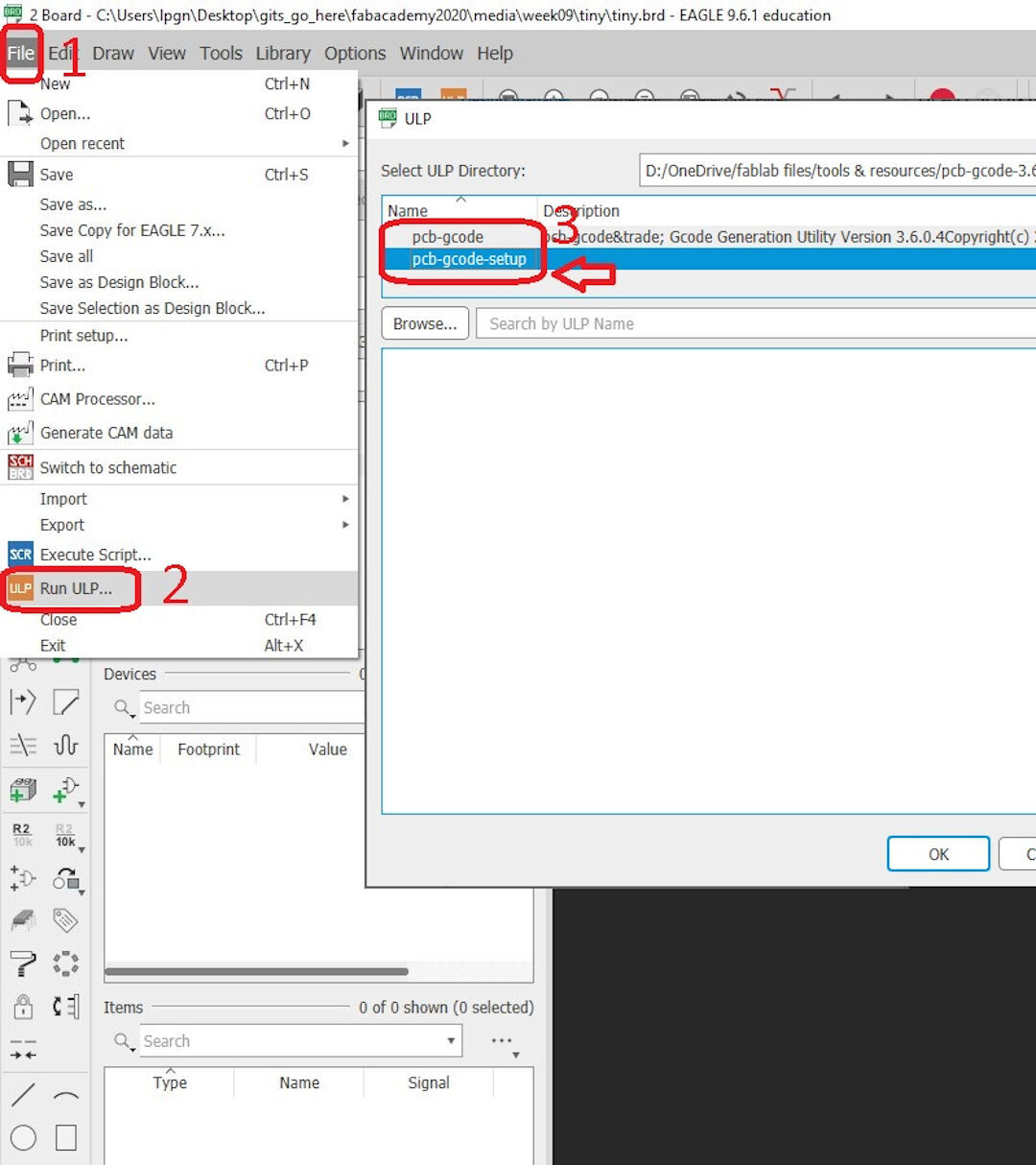
- Click file
- Then Run ULP
- Then click pcb-gcode-setup
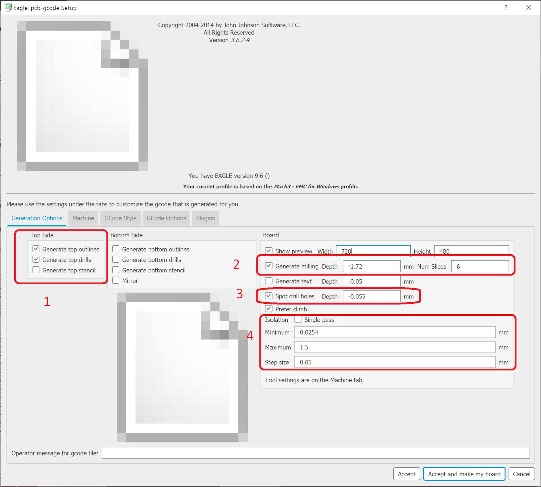
The settings I customized are:
- I chose to generate only top outlines and top drills: -the first is the generation of the board G-code to cut off the board from the stock. -the second is the holes the board might have. The thickness of the mill bit or drill is chosen in the machine tab
- Here, we can set the board thickness. My boards are separated well with a 1.72mm cut, and the "num Slices" I chose to do 6, meaning the board will be cut off in 6 passes.
- Spot drill holes are light markings made while etching the via and all features of the board design. It serves the purpose of alignment of the drill bit that can be used to drill the hole and prevent the bit heat from sliding on the board. My choice is 0.055mm, the same I have for etching.
- Isolation was one of the most important settings. This setting might slow down your computer a lot if the maximum is set too high. What works for me is: -minimum 0.0254mm (default); maximum 1.5mm; step size 0.05mm. The last one, together with maximum, will ensure 30 passes that will make sure there is no copper in between the traces and they are sufficiently isolated, reducing the risks of shorts. These numbers could be an exaggeration, but it is working very well, and I am obtaining gorgeous boards. In the future, I might reduce it or increase the step size.
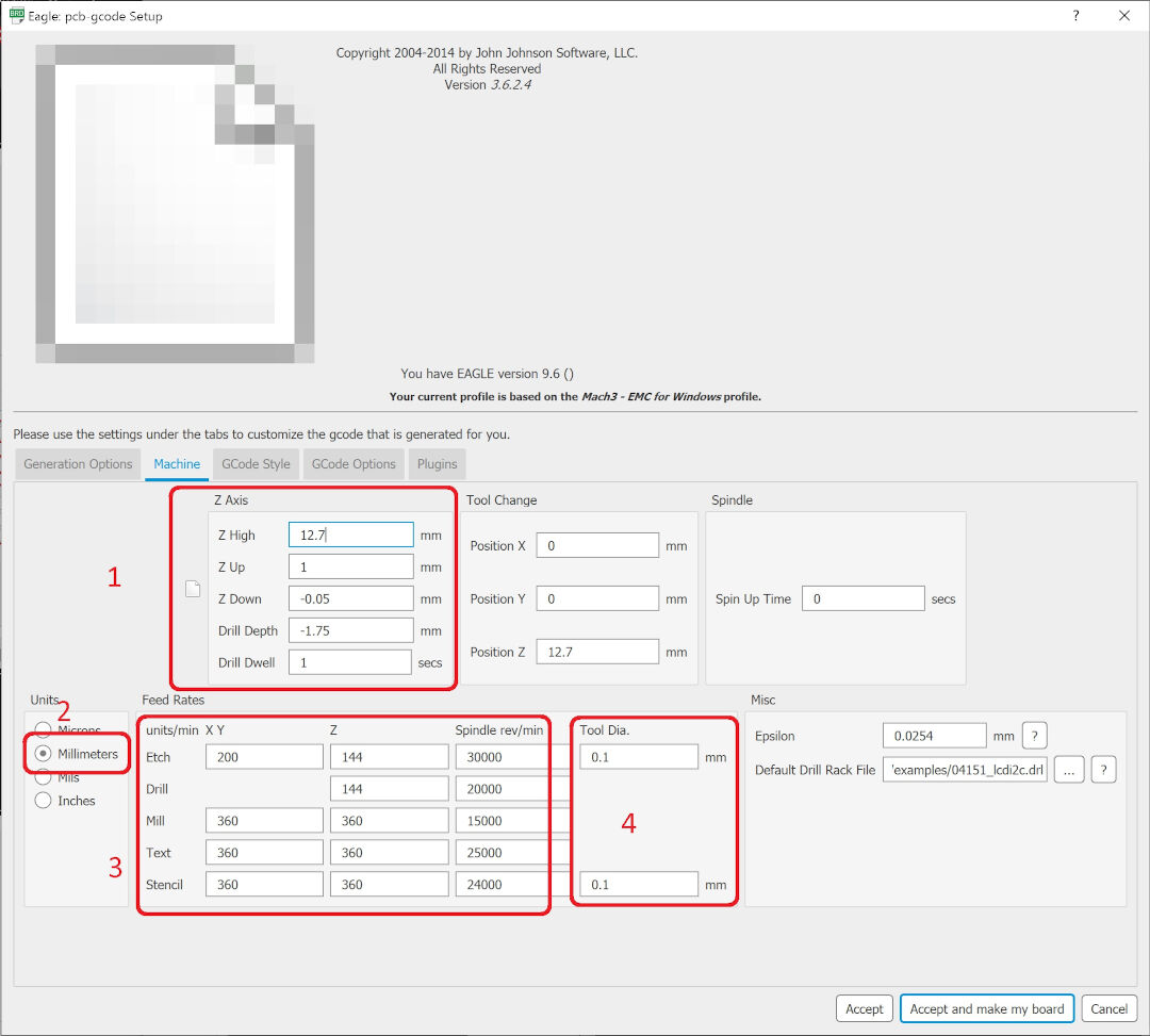
In the Machine tab, there are settings like depth of cuts, unit, feed rates, and tool diameter are chosen.
- - Z high is set to 12.7 (default), this setting should allow clearance for fixtures that could be in the way; -Z up is the clearance from the board when moving from location to location; -Z down is the depth of the cut. This number is very important in my case because I use a 10-degree V bit. If I go too deep, I cut more than I should, and if too shallow, I cut less. Of course, 10 degrees is not too steep and is more forgiving than a depth mistake with a more steep etching bit; - the drill depth is the depth of the through holes, and it should be generally a bit higher than the thickness of the blank PCB to account for imperfections; Drill dwell is the pause between each hole, it allows for cool down of the drill bit, I leave it default.
- Here, I set the unit as mm
- All my etching feed rates are default
- The tool diameter I use is 0.1 mm
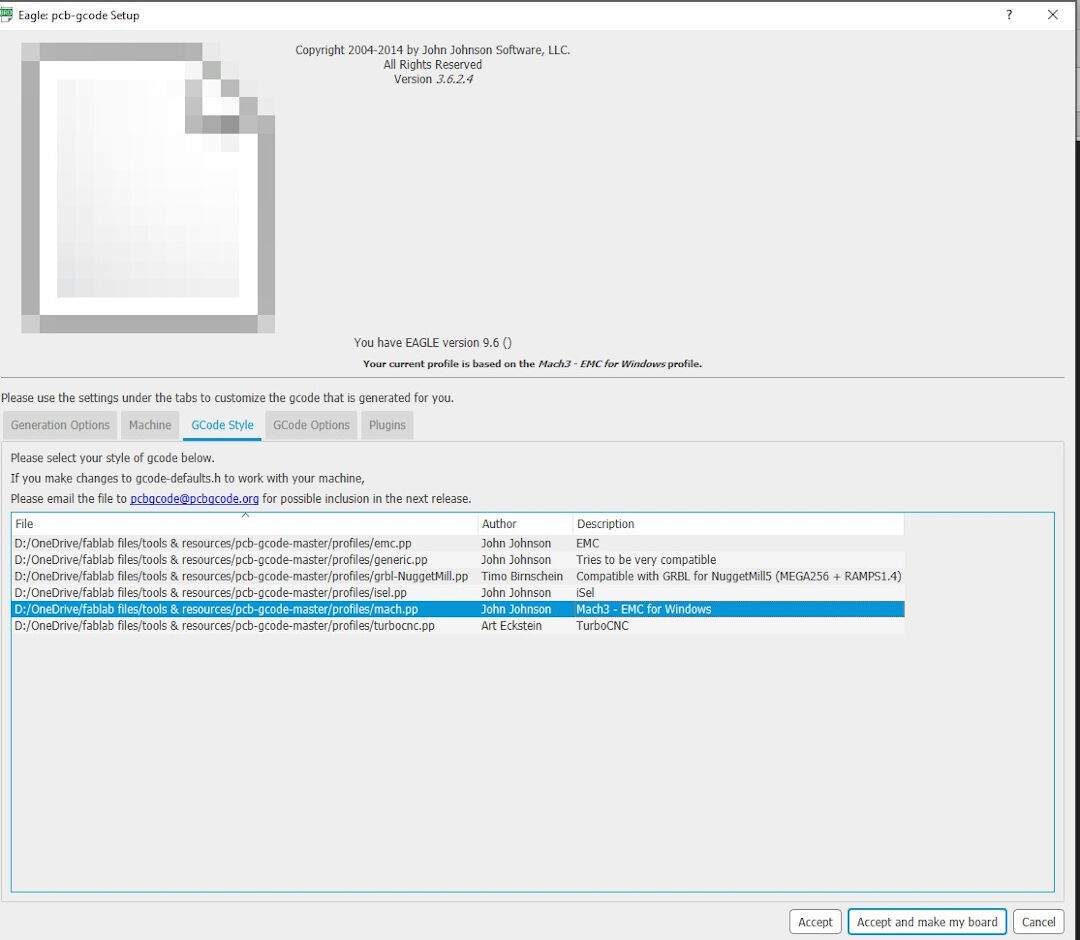
The G-code style tab is used to choose the post processor. I use Mach3.
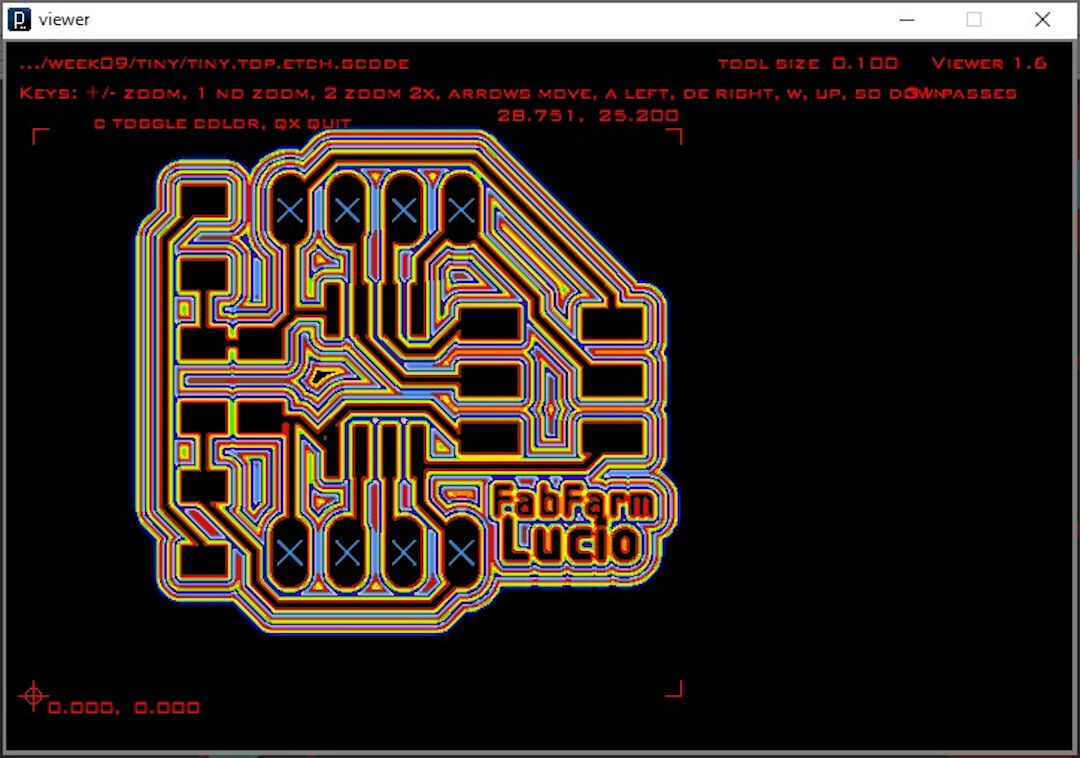
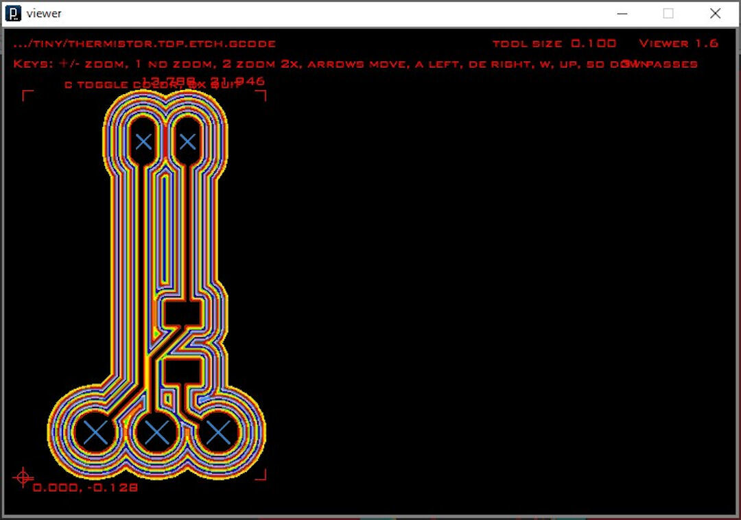
Here is the visualization of the G-code provided by the ULP. Arrows can be used to move around the image, as well as plus-minus signs.
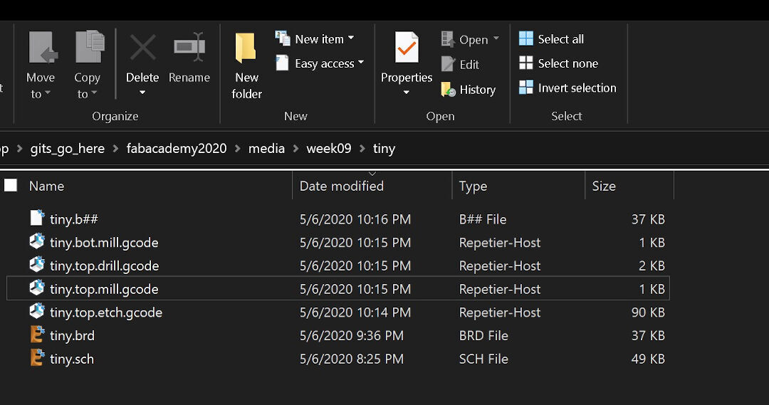
Four files get generated:
- *.bot.mill.gcode: it is the bottom milling (contour), I do not use this file.
- *.top.drill.gcode: is the G-code for the holes
- *.top.mill.gcode: is the file for the top layer contour, these files will allow detaching the PCB.
- Finally, *.top.etch.gcode is the G-code of the etching of the PCB containing all the features designed.
Below is the thermistor board isolation visualization.
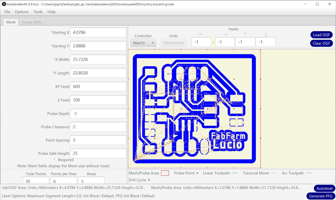
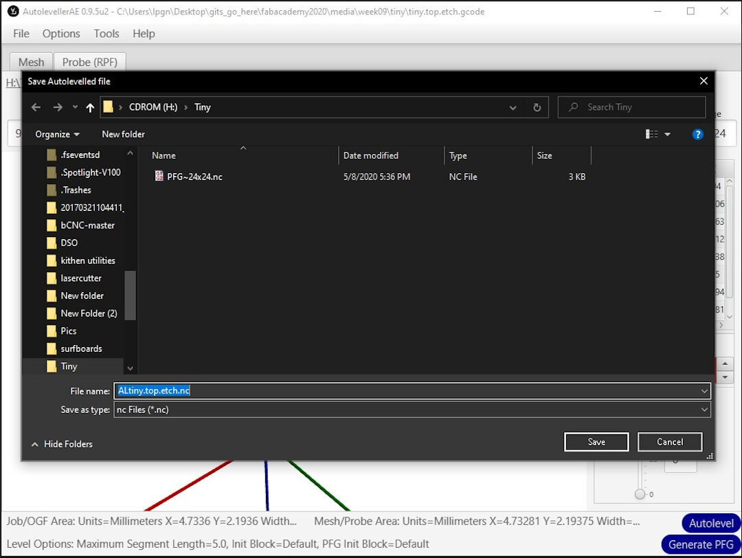
Autoleveller
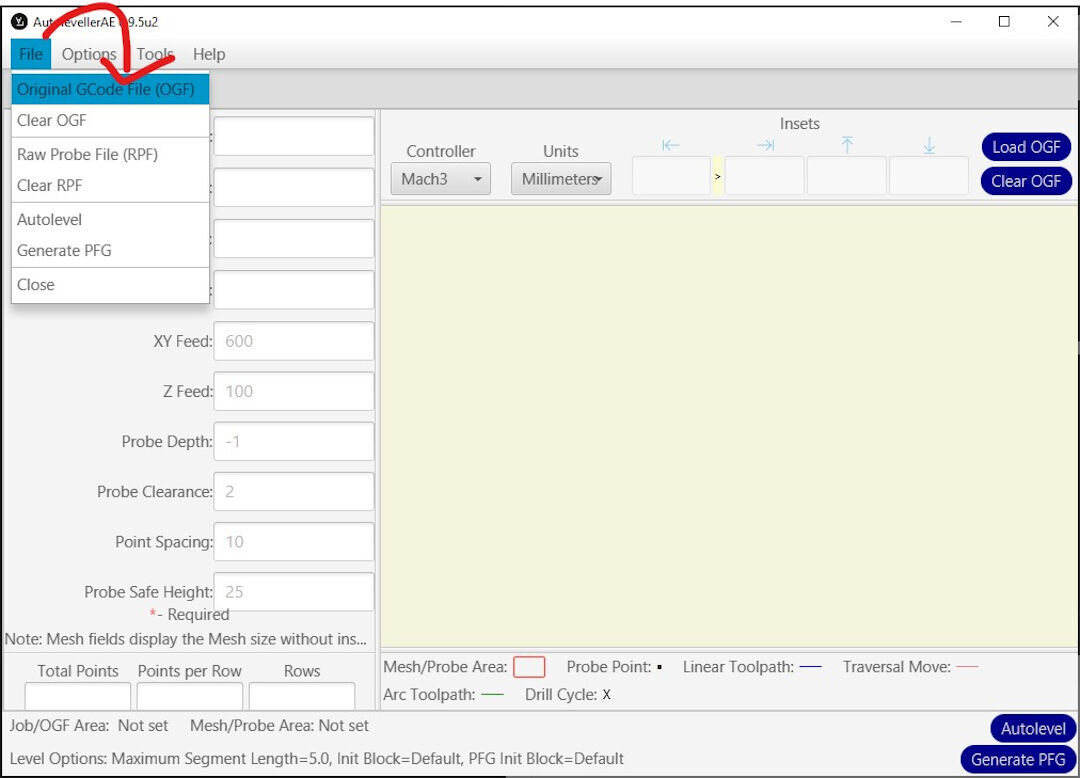
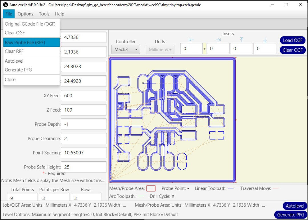
Autoleveller is a great software. By probing the blank PCB and then using the file generated to adjust the depth of cut of the G-code, it ensures the milling machine will follow the relief of the blank PCB. I start Autoleveller by running its executable; there is no installation needed on Linux. Next, click File and then Original G-code File (OFG): this will allow loading the original G-code in the program.
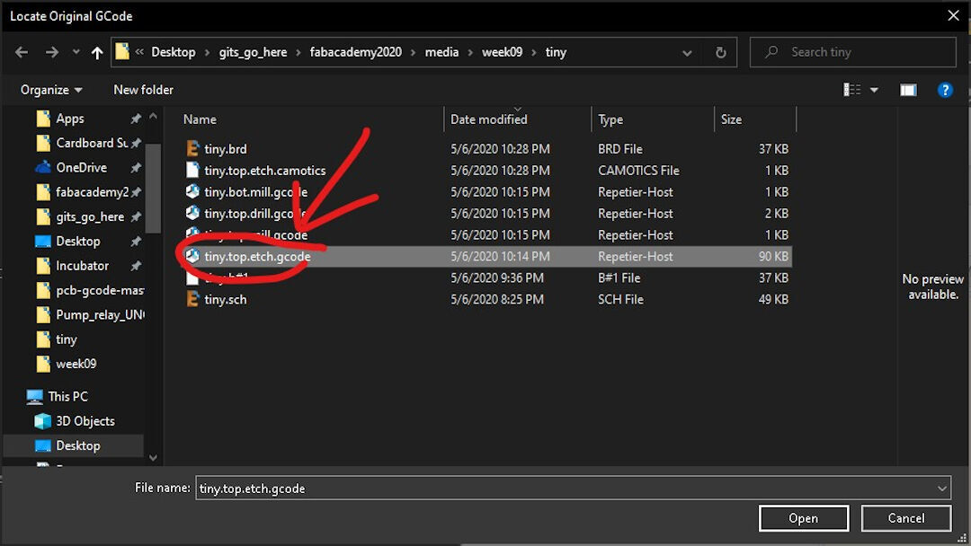
Click on the original G-code.
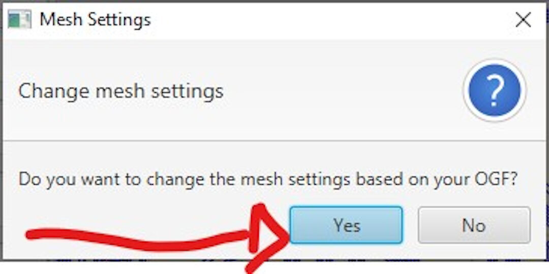
Click yes so the settings will be based on the file loaded.
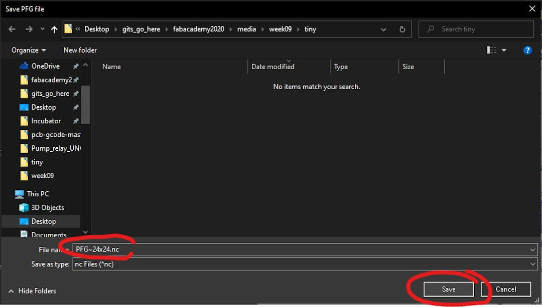
Next, click on Generate PFG on the bottom right of the window. This will create a G-code with a set of instructions. It will: -first probe the Z 0; -second probe several points in the area of the board; - third, it will ask for a location to save the raw file, which will later be used to create the autoleveled G-code.
This is the PFG file being saved. Next, load this G-code to the CNC and follow the instructions on the G-code area.
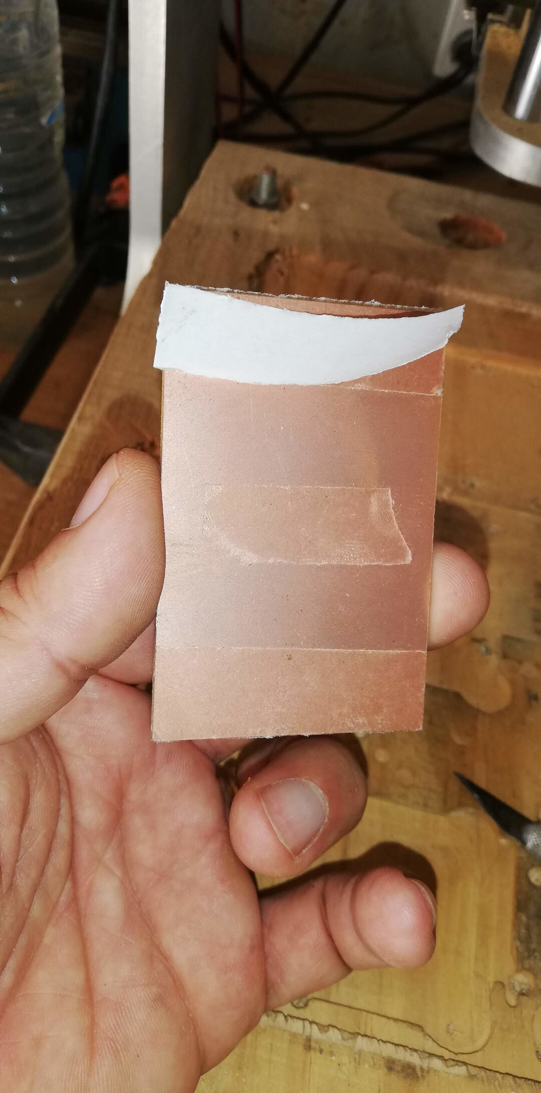
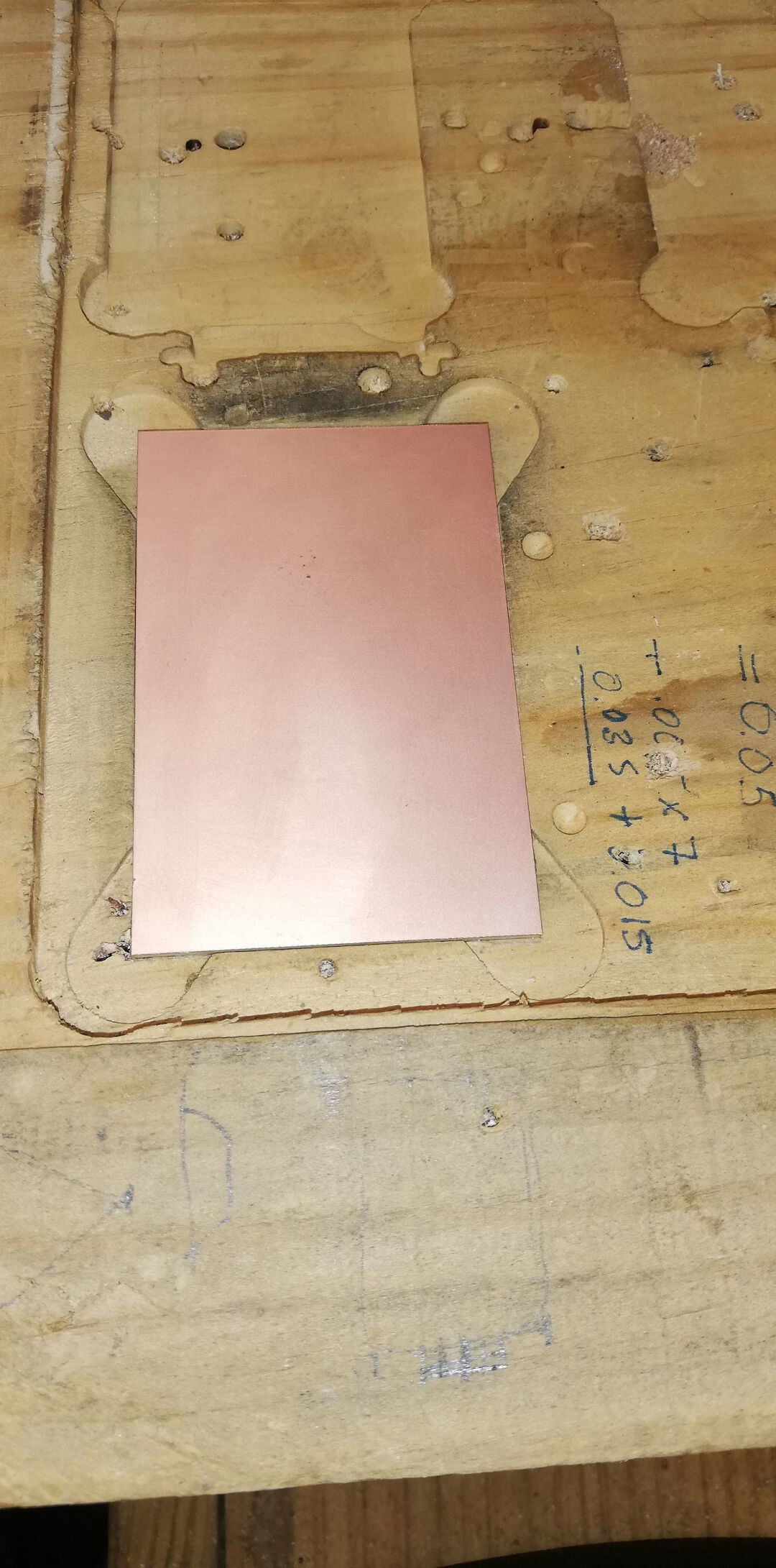
Now it's time to attach the blank PCB to the CNC bed. I am no longer using double-sided tape as it's not as effective as the fixtures, and there is also the need to clean up the leftover tape later.
In my CNC, I have machined a pocket prior so the board has a fixed location, which helps immobilize the blank.
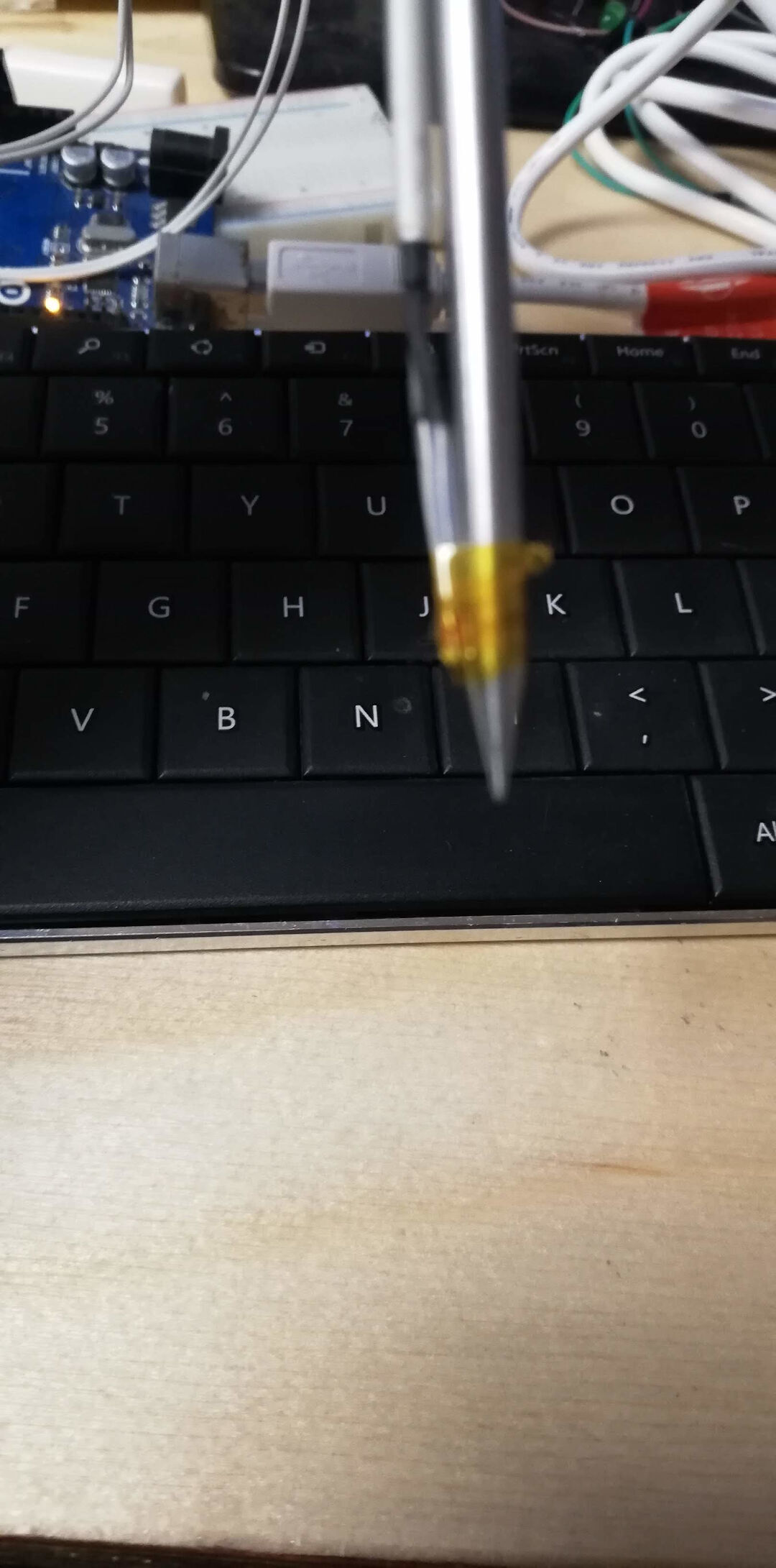
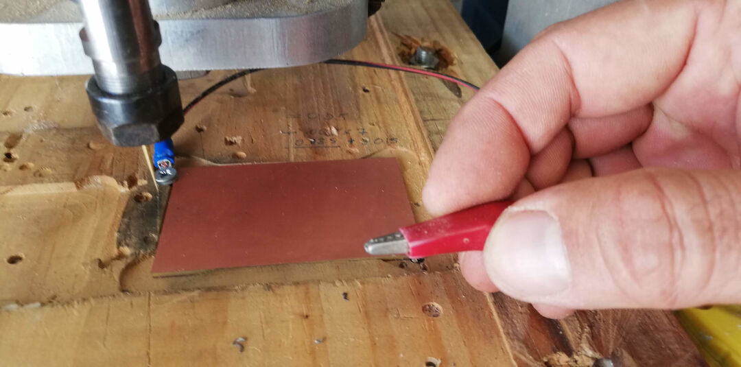
In the CNC, with the PFG loaded, follow the instruction on the screen by attaching the probe.
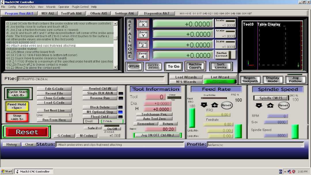
Here, I am attaching the probe to the surface of the board and the alligator clip to the mill bit.
This video shows the probing process.
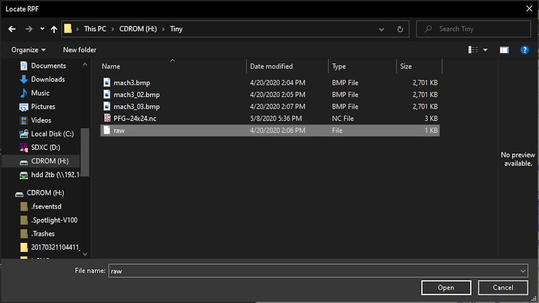
With the probing done, save the raw file and take it to Autoleveller and load it.
Load the raw probe file back into the Autoleveller.
Finally, save the adjusted G-code by clicking Autolevel on the bottom right of the screen. Save the file and take it to the CNC for the milling process to begin.
Machining Process Videos
The final result is here. Sometimes I use sandpaper 1000 grit to give it a better finish.
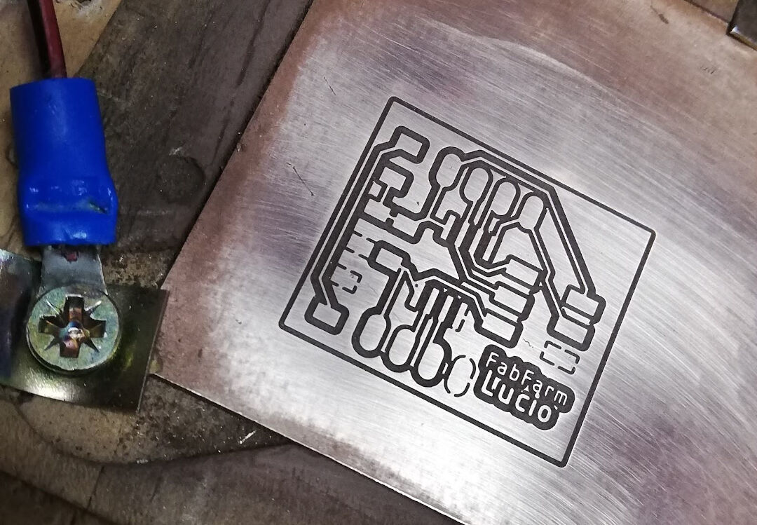
Now I am going to show the border being cut.
The Results
Footnotes
avrdude -Cavrdude.conf -v -pattiny45 -cusbasp -Pusb -e -Uefuse:w:0xff:m -Uhfuse:w:0xdf:m -Ulfuse:w:0xe2:m
Serial monitor: YouTube video
Attiny fan controller project: Robot Room
Reads temp with Arduino and NTC thermistor: Circuit Digest
Setup Arduino 022: High-Low Tech
Reflow oven project: Pleasant Software
Pull-up resistor (RES SMD 10K OHM 1% 1/4W 1206) from RST to VCC
Decoupling capacitor (CAP CER 1UF 50V X7R 1206) from VCC to GND to reduce noise