Final Project
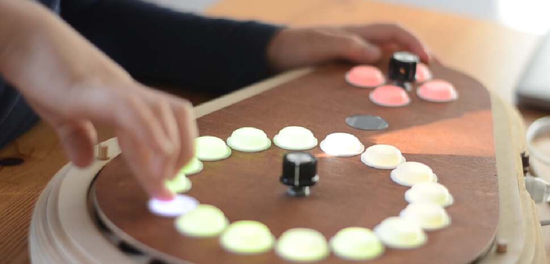
Final project Initial conception (Febuary 2022) Learning to play any musical instrument takes a very long time and a lot of effort. To enjoy music …
I like the idea of modular electronics design. Having small ICs, each doing their own little job, capable of working in parallel, makes designing time critical applications a bit simpler. For my final project I plan to make use of the I2C protocol because it allows me to have devices that only use two wires for communication and are daisy-chainable. I wanted to get some experience in building I2C student- and I2C master devices, so I started to design a small piezo speaker board that makes use of the Attiny412.
I was happy enough with the result to present it during the open review.
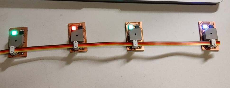
The end result is a network of piezo speakers that can play tunes by making each speaks act as a music channel.
| SpeakerNet playing the Mario tune |
| SpeakerNet playing the Monkey Island tune |
The ultimate goal is to have a chain of little speakers that are little, single channel synthesizers in themselves. Each speaker would receive commands on the I2C bus and play a note. Together the devices would be able to play complex compositions.
A single SpeakerNet board would have:
The choice for the I2C master device wasn’t very important. It should have enough power to hold and send entire songs to all the speakers. Eventually I chose e pre-existing board I made for the ESP8266.
At first I designed a board with an “ingoing” and “outgoing” I2C connector.
 |
|---|
| The first design contained too much connectors |
Later I realized I wouldn’t need those connectors on my board if I would use the 4-pin ribbon connectors that are in the Fablab inventory.
 |
|---|
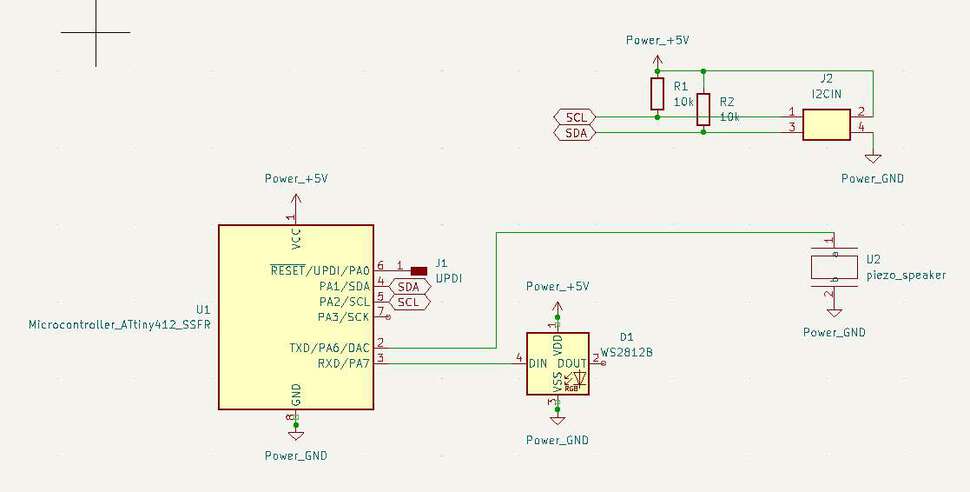
| The schematic of the SpeakerNet board |
I choose to make the UPDI pin a single pad on the board. This way I could program the board easily without a 3-pin connector taking up room on the board.
 |
|---|
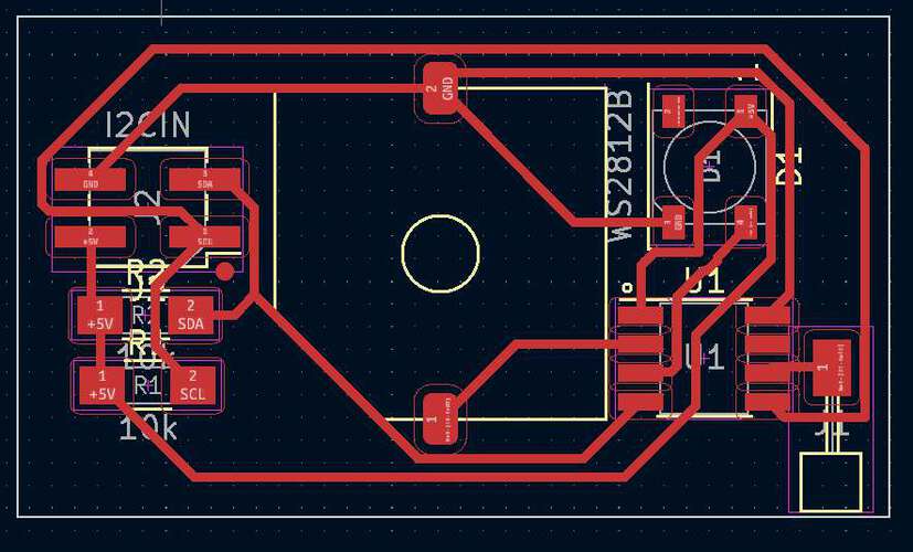
| The PCB design of the SpeakerNet board |
The board is very simple and came out pretty nice. Because I wanted to make a network of devices, I needed more, so I used the Gimp to duplicate the PNG images of the traces and the board outlines, so I could mill four boards at once.
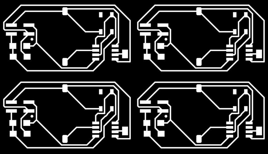 |
 |
|---|---|
| Four times the traces | Four times the interior |
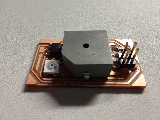 |
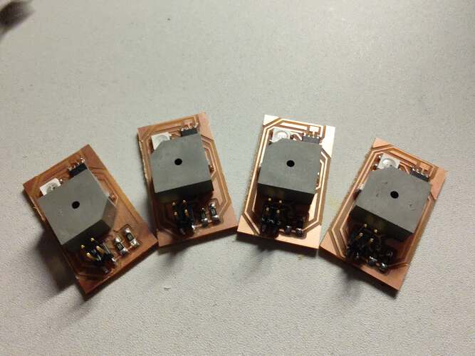 |
|---|---|
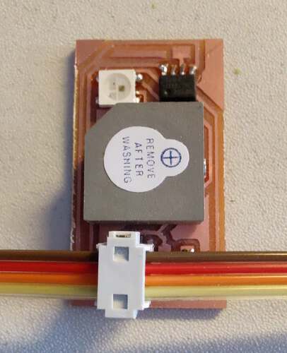
| The finished SpeakerNet board | Making a board makes it easy to duplicate |
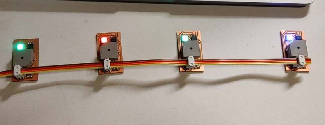
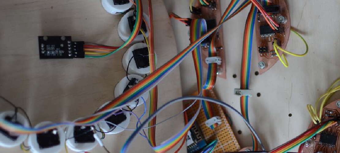
The connections between the boards are made using a 4-pin ribbon connector.
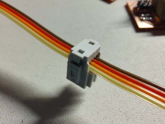 |
 |
|---|---|
| A single connector can be applied to any part of the ribbon | All devices are ion the bus. |
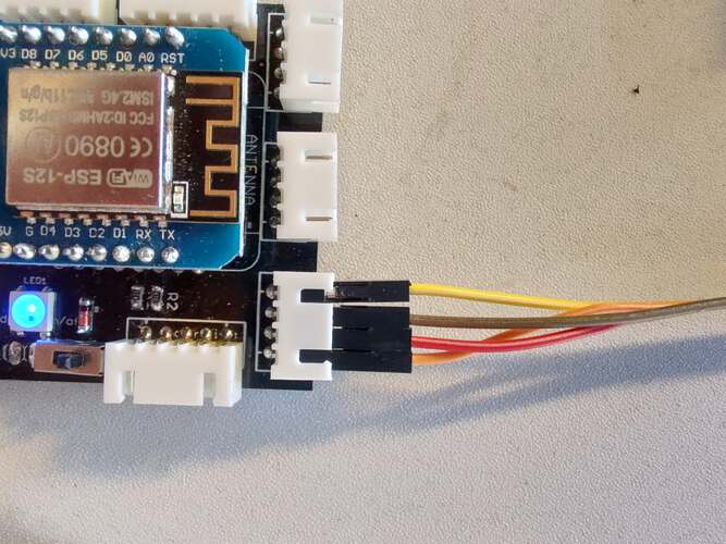
I soldered female dupont headers to the end of the ribbon cable to fit onto any master device.
 |
 |
|---|---|
| The connections to the board: brown: SDA, red: SCL, orange: GND, yellow:VCC | The connections to the ESP8266 board. Same colors apply. |
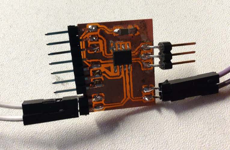
The Attiny412 has very limited output capabilities, and to keep my board simple, I didn’t bother to break out the UART pins. This made the board slightly harder to debug. Most of the testing was done on a version of the board with lots of pins broken out.
 |
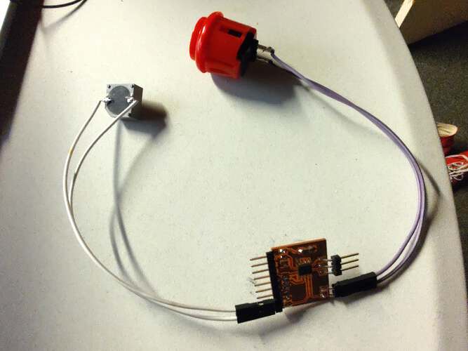 |
|---|---|
| The test board… | …in a test setup |
I made a very simple command structure for the board. Assuming a messages wouldn’t be send as a continuous stream, but rather as intermittently, a single command byte would suffice. The bytes that follow the command-byte can be interpreted as one or multiple parameters.
| I2C command | Explanation |
|---|---|
| C | Color, followed by four bytes, representing the r, g and b values, LSB first |
| P | Play a frequency, followed by two bytes representing the frequency of the tone, MSB first |
| S | Stop playing the note |
The first test was to read RGB values from the I2C bus and have the WS2812b LED take on the received color. I used the Wire->slave_read example and the tinyNEOPixel->simple and merged them into my own wirepixel sketch. It didn’t work.
At first I activated the LED directly in the receiveEvent() interrupt handle. I remembered to not perform many operations in an interrupt handler, so I moved the LED code to the main loop.
In the receiveEvent() function, the command is read from the I2C input buffer.
switch (command) {
    case 'C':
      ledTriggered = true;
      r = Wire.read();
      g = Wire.read();
      b = Wire.read();
      break;
}
And in the main loop, the LED is switched to the color that was read.
void loop()
    if (ledTriggered) {
        leds.setPixelColor(0, leds.Color(r, g, b));
        leds.show();
        ledTriggered = false;
    }
}
It still wouldn’t work. I removed code until I got the LED working again. It turned out the TinyNEOPixel library is not compatible with the Wire library. Fortunately there was also a TinyNEOPixel_static library included in the MegaTiny core. I didn’t understand the purpose or the distinction between the two, but the static version of the library can work with the Wire library, so I was relieved I didn’t make an unusable board.
To activate the tone, the command 'P' is received. The two bytes after the command are interpreted as the frequency. I considered to have only one byte and make that the midi-note, but to calculate the frequency from the midi note would take up too much space in the microcontroller, because it used floating points.
    case 'P':
      //Turn two bytes into a single 16-bit integer
      frequency = Wire.read() + Wire.read() * 256;
      toneTriggered = true;
      break;
    case 'S':
      noTone(SPEAKER_PIN);
      break;
Using the Wire->master_writer I wrote several functions that would send commands to a particular student device.
void sendColor(uint8_t address, uint32_t color) {
  Wire.beginTransmission(address);
  Wire.write('C');
  // Write a 32 bit int by pretending it is a poointer to 4 bytes
  Wire.write((uint8_t *)&color, 4);
  Wire.endTransmission();  // stop transmitting
}

void sendNote(uint8_t address, uint16_t frequency) {
  Wire.beginTransmission(address);
  Wire.write('P');
  // Write a 16 bit int by pretending it is a poointer to 2 bytes
  Wire.write((uint8_t *)&frequency, 2);
  Wire.endTransmission();  // stop transmitting
  sendColor(address, colors[iColor]);
}

void stopNote(uint8_t address) {
  Wire.beginTransmission(address);
  Wire.write('S');
  Wire.endTransmission();  // stop transmitting
}
Sending data larger than bytes involves a trick where I cast an uint32_t address to a pointer to bytes, thus interpreting it as a byte array. the least significant bytes is always first.
I found a command-line utility that converts midi files to c-code called miditones. In its simplest application it just accepts a midi file as input and outputs a c-code file with a static, pre-initialized array.
> ./miditones overworld.mid
MIDITONES V2.4, (C) 2011-2021 Len Shustek
  Processing 5 tracks.
  Only 4 tone generators were used.
  5947 bytes of score data were generated, representing 84.380 seconds of music with 1 tempo changes
  Done.
The generated output is a static array filled with byte literals:
const unsigned char score [] = {
// Grosse Fuge
0x90,55, 0x91,67, 0x92,43, 0x93,55, 0,36, 0x80, 0,3, 0x90,67, 0,36, 0x80, 0,3, 0x90,79, 12,86, 0x80, 0x81,
0x82, 0x83, 0,79, 0x90,67, 0x91,55, 0x92,43, 8,242, 0x80, 0x81, 0x82, 0,79, 0x90,68, 0x91,56, 0x92,44, 3,100, 0x80,
0x81, 0x82, 0,79, 0x90,77, 0x91,65, 0x92,53, 3,100, 0x80, 0x81, 0x82, 0,79, 0x90,76, 0x91,64, 0x92,52, 3,101, 0x80,
0x81, 0x82, 0,79, 0x90,68, 0x91,56, 0x92,44, 3,100, 0x80, 0x81, 0x82, 0,79, 0x90,69, 0x91,57, 0x92,45, 1,7, 0x80,
0x81, 0x82, 0,211, 0x90,78, 0x91,66, 0x92,54, 1,7, 0x80, 0x81, 0x82, 0,211, 0x90,81, 0x91,69, 0x92,57, 0,52, 0x90,79,
0x91,67, 0x92,55, 0,53, 0x90,81, 0x91,69, 0x92,57, 0,52, 0x90,79, 0x91,67, 0x92,55, 0,53, 0x90,78, 0x91,66
}
miditones supports up to 6 channels, so I need to build a bit more SpeakerNet boards.
| Stream command | Explanation |
|---|---|
| 0x9n | The 0x9n command plays a note on a channel. The channelnumber is represented by the n. The byte that follows is the midi-note. For example: {0x91, 69} plays an A4 on midi channel 1 |
| 0x8n | Stops any note playing on channel n |
| 0x0n | Pauses the stream for the amount of milliseconds in the following byte. n stands for the MSB part of the pause duration |
| 0xF0 | Signifies the end of the stream |
The final code for the interpeter is not up to my own quality standards, but there was no time to do it properly.
I was surprised that it actually worked. I still have about 1800 bytes left in the program memory opf the Attiny412. I hope I can get the Attiny DAC to act a bit faster than it currently does with analogWrite. It wouldn’t be far fetched to make each of these modules a more capable synthesizer with envelopes, filters and different waveforms to simulate instruments. I wish I had time to develop this project.
As I didn’t have a board that was ready to be connected to other projects, during the group project time I decided to quickly design and mill a simple board that could do I2C. That turned out to be the project I just described above.
Final project Initial conception (Febuary 2022) Learning to play any musical instrument takes a very long time and a lot of effort. To enjoy music …
What I did. I created the enclosure and designed and milled all the PCBs. TODO Hardware Priority 1 20 x Button LED caps 8x Octave1 8x Octave2 4x chord …