Week18: Project development
What I did. I created the enclosure and designed and milled all the PCBs. TODO Hardware Priority 1 20 x Button LED caps 8x Octave1 8x Octave2 4x chord …
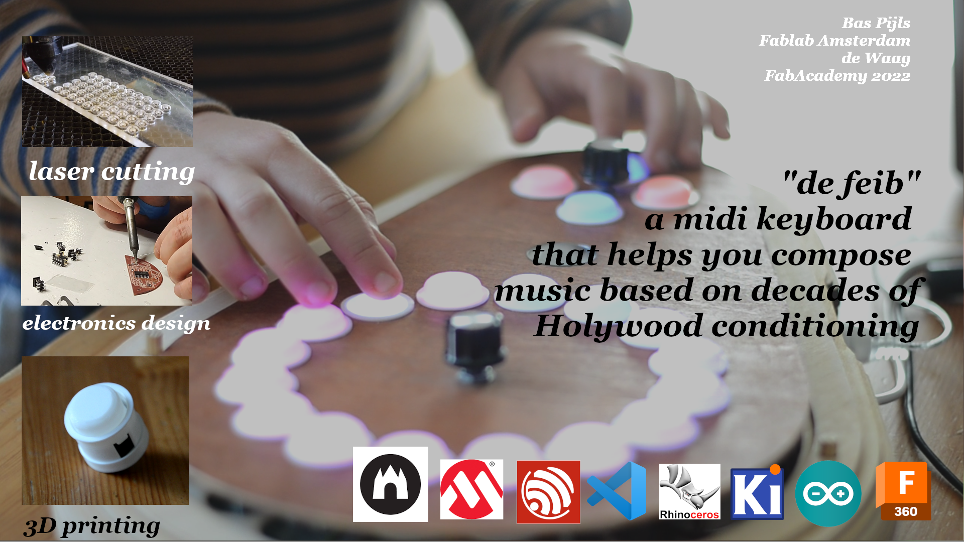
Learning to play any musical instrument takes a very long time and a lot of effort. To enjoy music hardly takes time at all. To bridge the gap between playing and enjoying music, I propose to make an instrument that limits the choice of the player in a way that they can always play agreeable music.
This instrument will be largely inspired by this YouTube video:
The instrument will be a midi-device based on a piano keyboard and it will be built with following requirements:
A rough demo can be played in this p5 program. Pressing the chord keys too rapidly will crash the browser sound engine (for now)
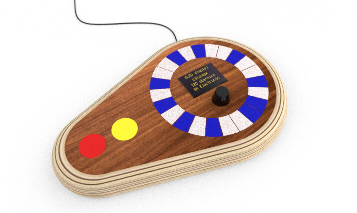
The final design could look like this:
| Date | Topic | Project actions |
|---|---|---|
| Jan/26 | principles and practices , project management | Set up my documentation environment and propose final project |
| Feb/02 | computer-aided design | Use multiple CAD programs to design multiple versions of the final project |
| Feb/09 | computer-controlled cutting | |
| Feb/16 | electronics production | Produce programmer |
| Feb/23 | 3D scanning and printing | |
| Mar/02 | electronics design | Design a board for two force sensitive keys |
| Mar/09 | computer-controlled machining | |
| Mar/16 | embedded programming | Create functional force sensitive piano keys |
| Mar/23 | molding and casting | |
| Mar/30 | output devices | Add ws2812 visual feedback to keys |
| Apr/06 | mechanical design, machine design | |
| Apr/13 | break | |
| Apr/20 | input devices | Analog signal conditioning |
| Apr/27 | networking and communications | Does Midi count? Otherwise, wifi connectivity. Otherwise I2C submodules |
| May/04 | interface and application programming | Make a webinterface to set advanced parameters |
| May/11 | wildcard week | |
| May/18 | applications and implications | |
| May/25 | invention, intellectual property, and income | |
| Jun/01 | project development | |
| Jun/08 | project presentations |
 |
|---|
| Final Presentation Slide |
| Final presentation video |
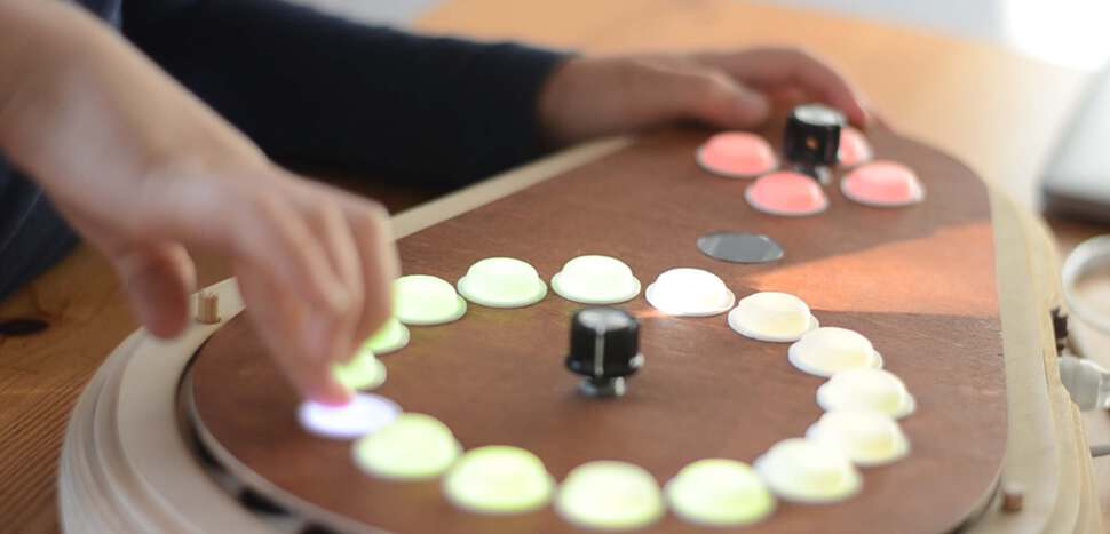
The enclosure of the device was designed to have a small selection of keys on the left and a large selection of keys on the right. The keys on the left play the chords, starting at the top and the chords progress in a clockwise fashion. The keys on the right hand side change, based on the chord that the user just pressed.
| The design and fabrication of the enclosure |
The enclosure is made from a stack of lasercut plywood. Designed in Fusion360 and sliced in Slicer for Fusion.
For the first iteration of the “feib” instrument I thought of making my own switches entirely from scratch by making a piece of metal touch two separated copper traces on my PCB.
 |
|---|
| Part of the switch is made up of two copper traces on the PCB that are made to be touched by another piece of copper foil |
| By touching two copper traces with a piece of aluminum foil, a button press can be registered. |
To make my own buttons would also involve designing and creating my own springs. That proved too much work so I opted for another solution.
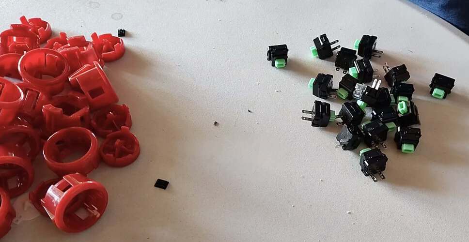
Eventually, the buttons I used were nothing special in terms of input. I used the switch-part of commercially available arcade buttons. T
 |
|---|
| The switches from arcade buttons were repurposed |
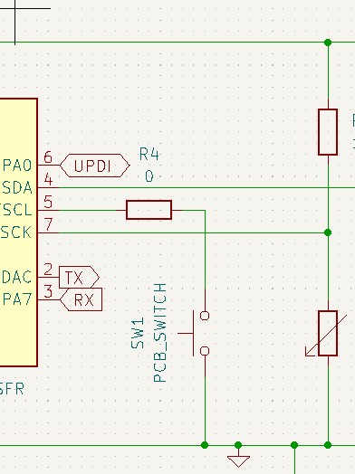
o prevent me from having to use resistors I used the internal pull-up resistor of the Attiny3216 microcontroller I used.All buttons were initialized using the following code:
for (uint8_t iButtonPin=0; iButtonPin<NBUTTONS; iButtonPin++)
    pinMode(iButtonPin, INPUT_PULLUP);
As the state of the buttons was only sampled for 100 times per second, I didn’t need debouncing, as button bounce occurs of much shorter time frames.
All eight button states could be stored as separate bits in one byte making it quite easy to perform edge detection for all eight buttons at once using binary operations:
void update(){
    lastPollButtonStates = inputState.buttons;

    // get current button state here
    // ....

    buttonsFallingEdge = ~inputState.buttons & lastPollButtonStates;
    buttonsRisingEdge = ~lastPollButtonStates & inputState.buttons;
}

// Functions below are there to get state of individual
// bits in the bytes representing the state of all 8 buttons
bool getButtonDown(uint8_t buttonIndex)
{
    return (inputState.buttons & (1 << buttonOrder[buttonIndex]));
}

bool getButtonPressed(uint8_t buttonIndex)
{
    return buttonsRisingEdge & (1 << buttonOrder[buttonIndex]);
}

bool getButtonReleased(uint8_t buttonIndex)
{
    return buttonsFallingEdge & (1 << buttonOrder[buttonIndex]);
}
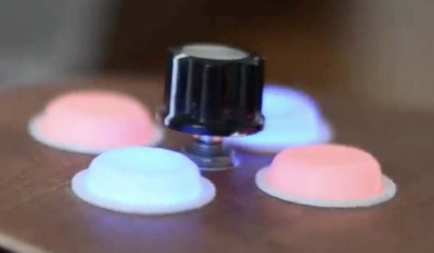
A rotary encoder is just a bunch of switched, turning on and off when a spindle is turned. The order in which the switches are activated determine the direction into which the spindle is turned.
 |
|---|
| The rotary encoder to select the chord progression |
I used a rotary encoder library by Matthias Hertel. I had to adapt the example files a bit because these included defines specifically for the Arduino Uno while I was using an Attiny3216. For each “click” of the encoder, the encoder library code returned an increment of two, so this could be divided by two to get the actual position.
To use the encoder to select from a limited number of menu items I simply used the modulo operator:
chordIndex = (keyboard->chordKeys->inputState.knobPosition % 10);
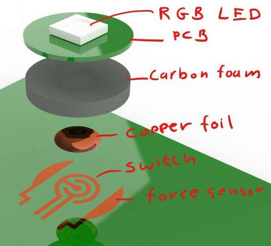
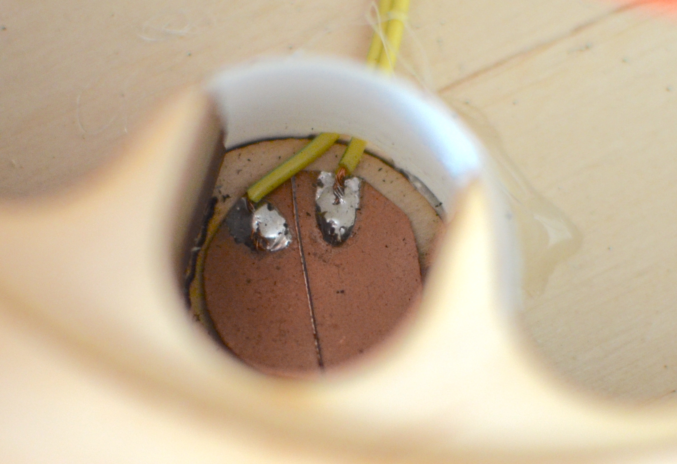
To enable aftertouch I used the conductive properties of carbon foam, inspired by an instructable the I’ve seen years ago. The carbon foam that is used to ship integrated circuits is slightly conductive. It gets more conductive when the material is more compressed. Putting a piece of carbon foam in a voltage divider circuit will and connecting the output to an analog input pin, a very simple and cheap pressure sensor is made.
 |
|---|
| The carbon foam was placed as a resistor in a voltage divider |
| Compressing the foam will yield changes in the signal that are large enough to use as a force sensor |
I was not interested in exact Newtons, Pascals or any other measure. Even non-linearity an hysteresis wouldn’t bother me, as the force readings would eventually be converted into a number used in the midi protocol, ranging from 0 to 128. Accuracy was not an issue.
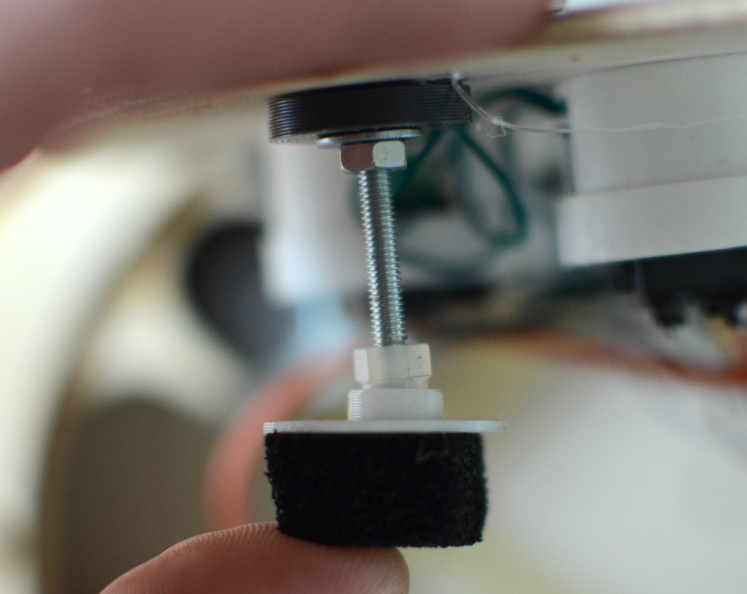
When making the instrument I opted out from making every key force sensitive. By making the lid of the device rest on four pieces of foam I was able to read the pressure in four corners of the device.
 |
 |
|---|---|
| An M3 bolt with an acorn nut at the end rests on a piece of carbon foam. The acorn nut acted as a ball-in-socket so bolt was able to rotate freely as to make the sensor only register downward pressure. | The carbon foam rests on a piece of copper-clad epoxy (PCB) with two separate pads. |
| Pressing the device at different locations on it’s lid will change the analog signals. |
Unfortunately I wasn’t able to make this work properly as an after touch function due to the limitations of the midi receiver.
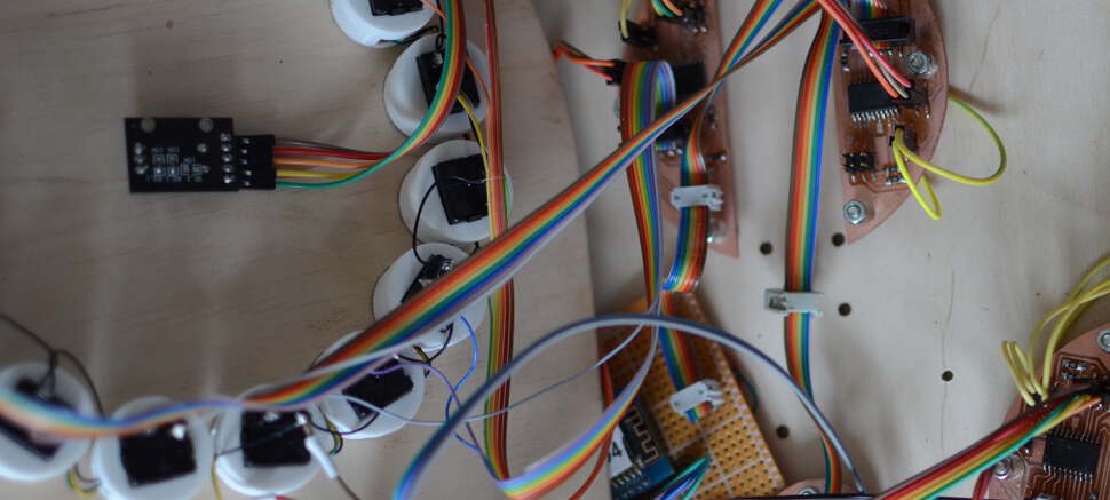
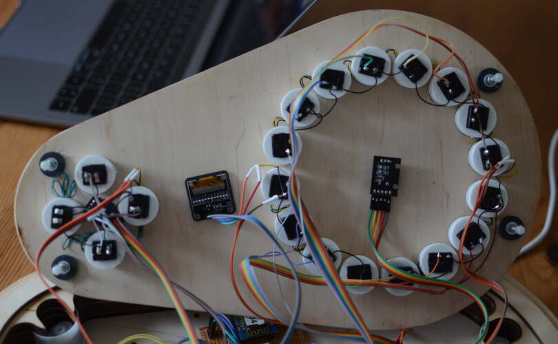
To light up the buttons on the “feib” instrument I used WS2812 LEDs, also called NeoPixels. I used the NeoPixel Static library, as the standard library didn’t play well with I2C.
| I cut a strip of NeoPixels to reconnect the using wires | A string of LEDs mounted on backplates, with holes for strain relief. |
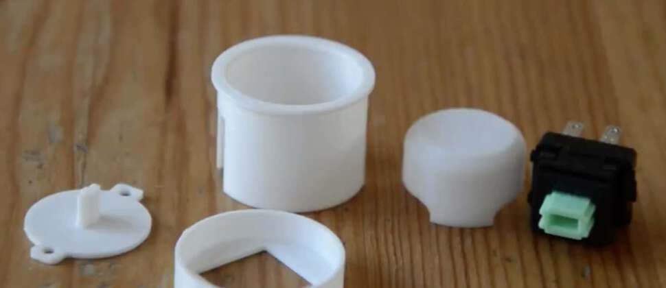
The LEDs needed to be cut up and resoldered because the needed to be part of a new enclosure for the buttons on my device. The original button enclosures were not at all translucent.
 |
|---|
| The new button enclosure consists of a shell, an LED backplate, a top cap and a bottom cap. |
 |
|---|
| The backside of the top panel of the “feib” device. The LEDs in the buttons are all linked together. |
The “feib” device contains an OLED display to show the state of the device. I found an OLED display that was small enough.
The only library I could find to work with the display ran on an ESP8266.
| The OLED display is used to show what chord progression is selected |
| Designator | Package | # | Designation | Supplier and ref | $ | |
|---|---|---|---|---|---|---|
| 1 | “R1,R4,R3,R2,R5” | R_1206 | 5 | 10kΩ | RC1206FR-0710KL | 0.01 |
| 2 | SW1 | Button_CnK_PTS636.0_6x3.5mm | 1 | Reset | PTS636 SM25F | 0.15 |
| 3 | U1 | ESP-12E | 1 | ESP-12F | ESP12F | 5 |
| 4 | SW2 | Button_CnK_PTS636.0_6x3.5mm | 1 | Program | PTS636 SM25F | 0.15 |
| 5 | J1 | PinHeader_2x03_P2.54mm_Vertical_SMD | 1 | I2C_3V3 | 95278-101-04LF | 0.3 |
| 6 | C1 | C_1206 | 1 | 1uF | C3216X7R1H105K160AB | 0.07 |
| 7 | J2 | PinHeader_1x02_P2.54mm_Horizontal_SMD | 1 | PinHeader_1x02 | GBC36SGSN-M89 | 0.05 |
| Designator | Package | # | Designation | Supplier and ref | $ | Σ$ | |
|---|---|---|---|---|---|---|---|
| 1 | “J4,J1,J6” | PinHeader_2x02_P2.54mm_Vertical_SMD | 3 | PinHeader_2x02 | S9012E-02-ND | 0. | 3 |
| 2 | “R1,R2” | R_1206 | 2 | 10kΩ | RC1206FR-0710KL | 0.01 | 0.02 |
| 3 | U1 | SOIC-20_7.5x12.8mm_P1.27mm | 1 | Microcontroller_ATtiny3216-SFR | ATTINY3226-SU | 1.3 | 1.3 |
| 5 | “R3,R4” | R_1206 | 2 | 4k7Ω | RC1206FR-074R99L | 0.01 | 0.02 |
| 6 | J5 | PinHeader_2x03_P2.54mm_Vertical_SMD | 1 | PinHeader_2x03 | 95278-101-04LF | 0.4 | 0.4 |
| 7 | J2 | PinHeader_2x04_P2.54mm_Vertical_SMD | 1 | PinHeader_2x04 | 609-6529-ND | 0.5 | 0.5 |
| 8 | R5 | R_1206 | 1 | 0Ω | RC1206FR-070RL | 0.01 | 0.01 |
The tactile switches are repurposed from existing 24mm arcade buttons from AliExpress at $0.27 per piece for a total cost of 20x0.27=$5.4.
The WS2812 LEDs were cut from a strip of LEDs from AliExpress at $0.062 per piece, for a total cost of 20x0.062=$1.24.
For the enclosure I used an estimated 2m^2 of 3mm thick multiplex at $18 per m^2, for a total of $36,- The wiring is estimated to be a total of $5,-.
The total cost of materials of the device would be an estimate $60,-. The most efficient way to cut the costs would be to more economically cut the slices of the enclosure from the available wooden plates.
What I did. I created the enclosure and designed and milled all the PCBs. TODO Hardware Priority 1 20 x Button LED caps 8x Octave1 8x Octave2 4x chord …

Final project, Slide and video If the final project turns out as I imagined it and eventually proves to be useful I might want to think about ways to …