Final Project
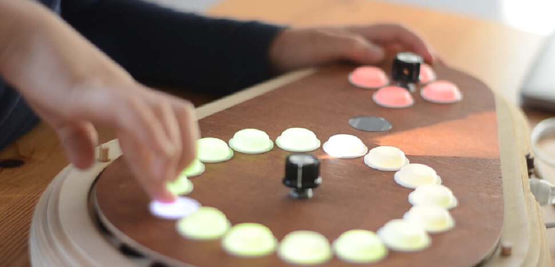
Final project Initial conception (Febuary 2022) Learning to play any musical instrument takes a very long time and a lot of effort. To enjoy music …
Connecting your embedded devices to the internet can have some real benefits. One thing that always remains a nuisance is to find your device on the world wide web of connected computers by determining it’s IP address. To obtain the IP address, a user must often resort to having a display or opening up another communication channel to your device, typically a serial connection.
I have this problem quite often when students have to connect a large number of devices simultaneously in a classroom setting. This made me start looking for an answer to the following question:
How can I communicate a device’s IP address or other unique identifier to an end-user?
The solution should be:
Ways to do this would be:
Eventually I chose to explore whether it would be possible to encode data in the flashing pattern of an RGB LED
I was happy enough with the result I decided to present it at the Open Review.
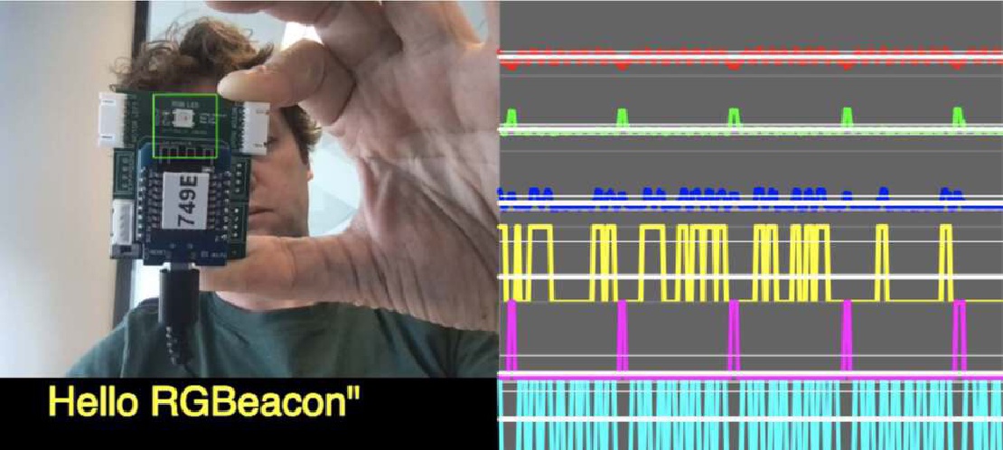
The microcontroller flashes an RGB LED in a specific pattern. A JavaScript application is written to analyze the pattern, interpret the bits and bytes and convert it back into readable data.
By keeping a flashing RGB LED in the green-marked region, the R, G and B channels of the webcam input are interpreted as CLOCK, BYTE and BIT information respectively |
Besides sending text, the microcontroller can be programmed to send out it’s IP address as separate bytes.
| The webapplication can create a link to the detected IP address so a user can easily find and control the device through it’s web interface |
For the code examples to run out of the box, it’s necessary to:
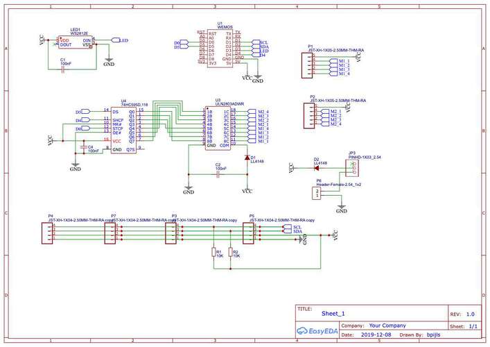
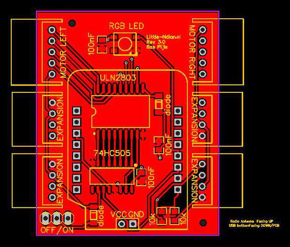
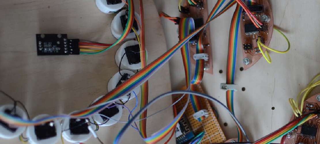
I chose to connect a WS2812b RGB LED to an ESP8266 microcontroller. I already had a PCB lying around which I designed to drive little classroom robots.
 |
 |
|---|---|
| The schematic for the “Little-Endian” classroom robot | The PCB for the “Little-Endian” classroom robot. The PCB was designed and manufactured before FabAcademy. |
A lot of components on this PCB are not significant for this demonstration but this is what I used for testing.
For the RGB-LED to reliably send data a synchronous communication protocol was chosen. An RGB LED is basically three LEDS in one so each color channel is able to play a different role. A little serial communication protocol was made to turn the red, green and blue channels of the LED on in different combinations and the point it towards my webcam and see what color it returned.
if (Serial.available())
  {
    val = Serial.read();
    switch (val)
    {
      case 'r': r = BRIGHTNESS_R; break;
      case 'e': r = 0; break;
      case 'g': g = BRIGHTNESS_G; break;
      case 'f': g = 0; break;
      case 'b': b = BRIGHTNESS_B; break;
      case 'v': b = 0; break;
      case 's':
        sending = true;
        bitIndex = 0; clockBit = 0; break;
      case 'S': sending = false; break;
    }
  }
When the character 's' is sent, the ws2812 starts flashing in a certain pattern:
| Channel | Description |
|---|---|
| Red | the clock signal, flashing on and of for each bit |
| Green | the byte signal. Flashes bright green to signify the beginning of a new byte. The clock signal is low when flashing for a new byte |
| Blue | The bit signal. Flashes when an individual bit in the outgoing data is high |
When flashing the bytes, the FLASH_INTERVAL will determine how fast the LED will flash it’s bits. The sampling rate of the camera that picks up the signal is assumed to be between 24 and 30fps. Flashing bits at a rate of over half this frequency will result in aliasing. Keeping the FLASH_INTERVAL at 75ms will keep it slightly above the Nyquist frequency of 15Hz.
Determining whether to flash the bit channel is done by shifting the byte to send:
// Creates a unit32_t that represents whether the bit at <bitIndex> is high or low
uint32_t createDataColor(uint8_t dataByte, uint8_t bitIndex)
{
  return BRIGHTNESS_R << 16 | // Set the red (clock) channel to HIGH
         //determine wether the bit at <bitIndex> in <dataByte> is high
         BRIGHTNESS_B * ((dataByte & (1 << (7 - bitIndex))) > 0);
}
Timing is done using millis() and determining the state (flashing a bit, clock or byte) is done using an ugly pile of nested if-statements.
The Webcam code should run in a browser, as this is an application to turn flashes of light into an IP address. Using P5.js makes it easy to get to activate a webcam and to draw shapes on a canvas. I am using the Facetime camera of my MacBook Pro 13" 2019.
The end-user should point a camera to the RGB-LED. I don’t have to scan the entire image, so I defined a specific region of the screen in which I scan for color changes. The average color in the region was determined to see whether separate flashes could be picked up with the webcam.
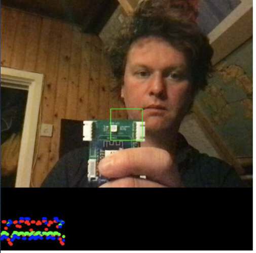 |
|---|
| The first iteration looked like this. The average red, green and blue components were drawn below the web-cam image as separate circles |
At a later stage some code was introduced to handle rudimentary signal processing and a better way to plot timeseries.
| Using the fist prototype, the effect of the different color combinations of the LED could be determined. |
As it turns out, activating separate colors of the LED will not purely activate the corresponding channels of the webcam. This is probably due to the webcam being smart and dynamically trying to correct colors and dynamic white balancing. There is a certain amount of cross-talk between the color channels. Especially the blue and green channels affect each other. Red is quite unaffected by both. Luckily there is enough information to differentiate the signals.
The conversion from raw signals to bits and bytes is done by using some simple rules and statistics.
| Type of Signal | Processing method |
|---|---|
clock |
The red signal is turned into a clock signal by triggering it at a threshold of 2 times the standard deviation of the signal over 300 samples |
bit |
The bit signal is generated by comparing the green and the blue signals. Green>blue, bit = 0, Blue>green, bit = 1 |
byte |
A byte is finished by detecting a flash of green at 1.5 times it’s standard deviation over 300 samples |
A bit is detected by determining the state of the bit signal at two samples before a rising edge of the clock signal. A byte is detected at the rising edge of the byte signal. When a byte event is detected, all eight previously received bits are converted to a byte. One thing to look out for is the unavailability of unsigned data types in JavaScript. When interpreting the received byte as a number, 128 should be added to the byte in order to convert it to an unsigned byte. When converting the byte to an ASCII character, the byte should be left alone.
| Upload a version of hello_rgbeacon sketch to your Arduino-compatible board with a WS2812 attached to it. Press the “Enable WebCam” button and keep the LED in the green region of the video display to watch the message appear. |
|---|
It is possible to send data to a device with a webcam using a cheap RGB LED. By sending an IP address from the microcontroller to a device with a web browser it is shown that sending data this way can be useful. Other useful applications might be:
At this point sending data using and RGB LED and a webcam is quite slow and error prone but there is a lot of room for refinements and improvements:
On the hardware side:
On the webcam side:
Eventually this should be turned into an Arduino library and a nicely encapsulated JavaScript library for use in actual applications. This is purely a proof of concept.
For the group project I prepared a tutorial for my fellow students to get experienced in Processing and connect Processing applications to your microcontroller using serial communication. The tutorial can be found here.
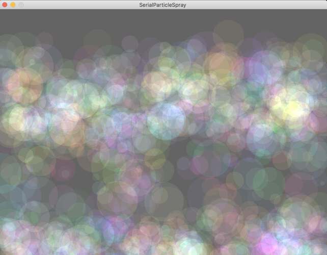 |
|---|
| The result was a particle system that emitted particles based on a serial input value. |
Furthermore, Bente showed us how to use WebSockets to communicate with a web-page. Using an ESP8266 and a websocket library we were able to send data to a website when a button was pressed.
Final project Initial conception (Febuary 2022) Learning to play any musical instrument takes a very long time and a lot of effort. To enjoy music …
What I did. I created the enclosure and designed and milled all the PCBs. TODO Hardware Priority 1 20 x Button LED caps 8x Octave1 8x Octave2 4x chord …