Final Project
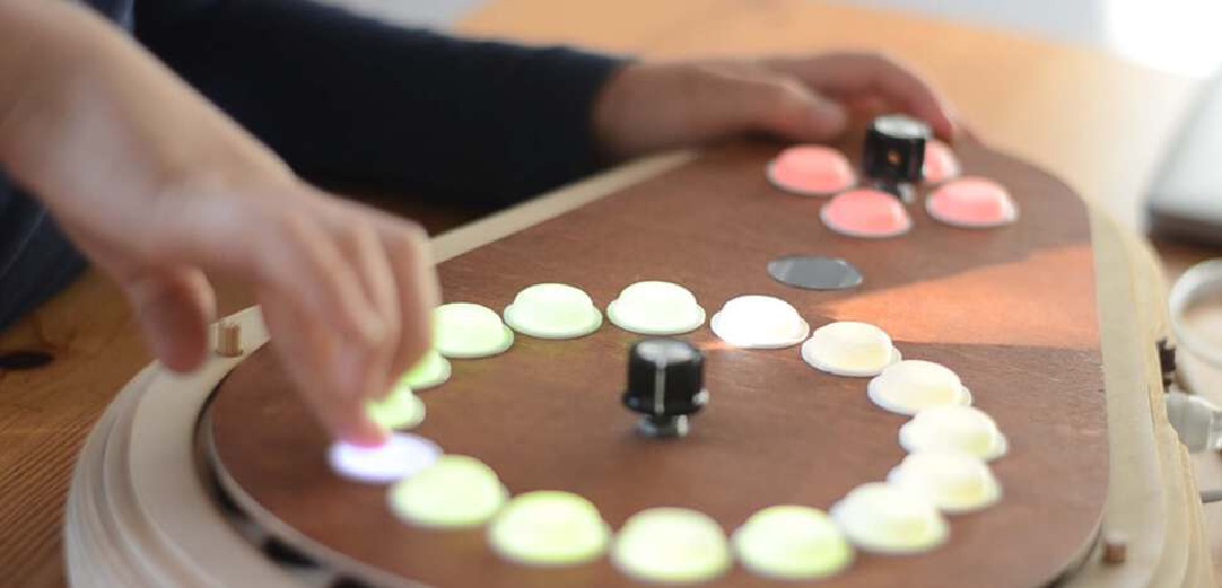
Final project Initial conception (Febuary 2022) Learning to play any musical instrument takes a very long time and a lot of effort. To enjoy music …
I am not new to 3d printing. When the rep-rap project started in around 2006 I didn’t have the means or the connections to get involved, but when the MakerBot Cupcake was sold as one of the first cheap commercially available 3d printers, I knew I had to get one. It’s still mostly in one piece, collecting dust on the top-shelf of my workplace. In time I have built some printers and I have now settled on an Ender 3, which has served me well over the last couple of years. I mostly use it for personal projects and to print little toys and replacement parts.
Because I have some experience in 3d printing I wanted to challenge myself and see if I could use my 3d printer without using slicer software. I had read somewhere that there was an application that could help users to generate their own GCode scripts for 3d printing, but unfortunately I forgot the name of the application, so I started a GCode generator myself. I chose the Processing programming environment for this so I could very quickly get visual feedback from my work.
After I was well under way I found the GCode authoring tool. It is called FullControl and it it an Excel script with a lot of VBA macros. It allows the user to copy-paste rows in an Excel table which the macros then turn into GCode to copy paste into a file or printer. The paper was very inspiring.
I was happy enough with the result I presented it voluntarily in the open review.
I made use of a classic Ender-3 with BLTouch bed levelling sensor. For all the prints for this experiment I used PLA, mostly sourced from “Internet of Printing” and eSun. Most of the print jobs ran from an SD card but for some quick testing I had the printer hooked up to a PC running Ubuntu and Pronterface.
The GCode generator was written in Processing/Java for the following reasons:
 |
 |
|---|---|
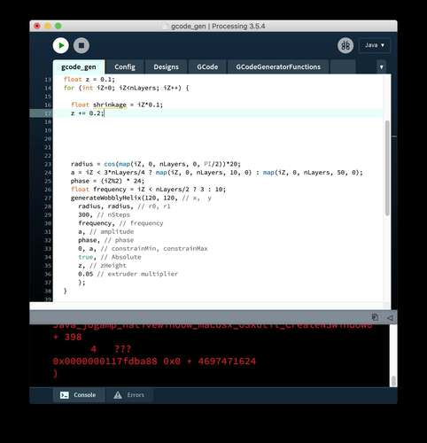
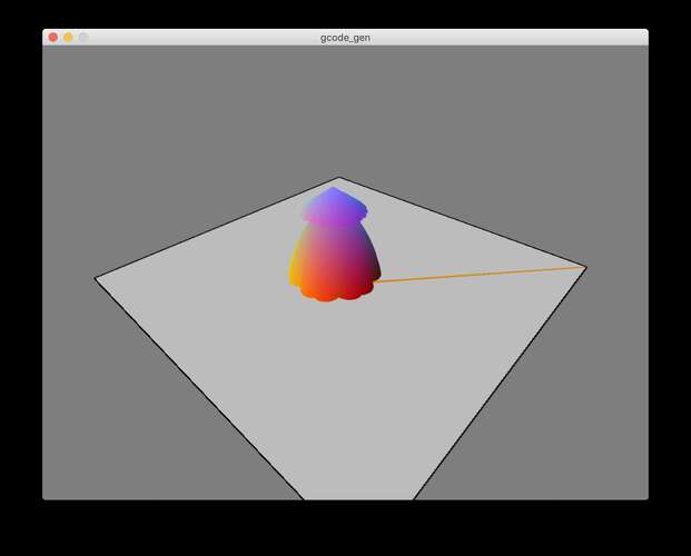
| The eventual processing code main sketch | The output window. |
I started out by creating a small, flat (1 layer) rectangle in openSCAD and slicing the STL with CURA. This gave me a simple example of what GCode form my printer should look like. The resulting file had thee distinct sections:
| Section | Purpose |
|---|---|
| Before printing |
|
| Printing |
|
| After printing |
|
In my code, I separated the gcode before printing and the gcode after printing in separate files. These strings are always attached before and after my generated gcode so I don’t have to write code for it to support those commands.
For the first generated gcode I wanted to try and do a “non-planar” path by making the z-axis move while moving the printhead in the XY-plane.
This snippet of code shows the trajectory of the printhead:
    x = bedSize/2 + r * cos(fi);
    y = bedSize/2 + r * sin(fi);
    z = abs(sin(fi*10))*5;
    r=fi*10;
| The absolute sine wave makes the z-axis perform a kind of hopping motion. |
The first results were interesting. It seemed that the printhead deposited a string of plastic, and periodically “glue” a little blob to the surface. This was exactly what I needed for printing micro-structures so I kept at it. But in subsequent prints there was no plastic fed through the extruder. Re-examining my example gcode again and watching a GCode tutorial video by CNC Kitchen I realized I made a mistake.
| Absolute vs Relative extrusion |
|---|
A command in the “front-matter.gcode”, M82, set the extrusion to “absolute” which meant it interprets the E parameters in the G1 commands as the absolute amount of material extruded since the beginning of the print. I interpreted the value as a relative value, i.e.: how much material was being added for this particular command. I chose to change M82 to M83 in the front-matter.gcode file to set it to relative extrusion. |
Having fixed the extrusion and inspired by the hopping traces, I started to test more non-planar printing.
 |
 |
|---|---|
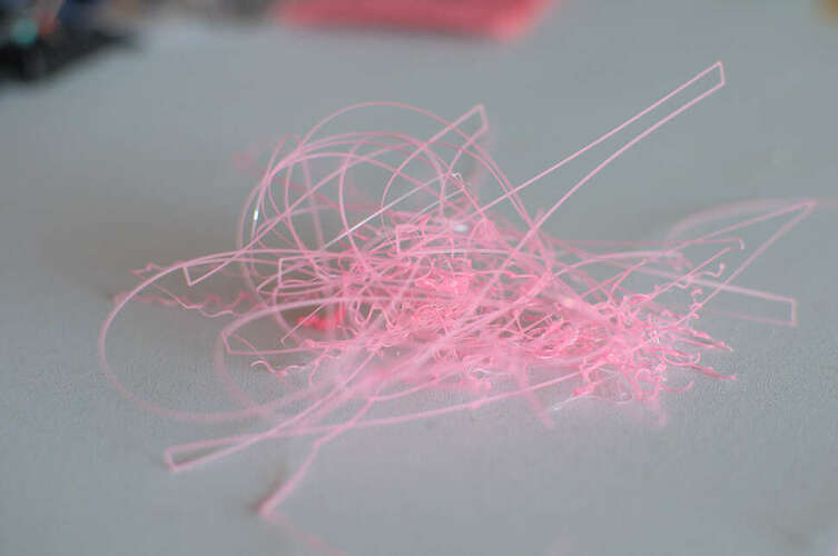
| I printed several, what I now call, “hoppy” lines | But eventually they all failed. |
I started doing the advanced stuff way too early. First I decided to keep it simple.
A grid is simple. It’s just a bunch of straight lines. Creating gcode for a grid is less simple because you have to take the physical movement of the printhead into account. You want to print parallel, consecutive lines in opposite direction otherwise there is a big chance the already deposited line will be ripped off.
 |
 |
|---|---|
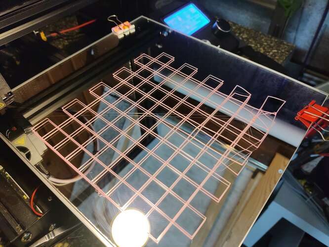
| Eventually I was able to print a grid. | With some imagination this might become a way to print special types of fabric. |
Now that the grid worked, it was a small step to print a stack if shrinking grids.
int nLayers = 50;
for (int iZ=0; iZ<nLayers; iZ++) {
    float shrinkage = iZ*0.1;
    float z = 0.1 + iZ*0.2;
    // Grid pyramid
    generateGrid(100+shrinkage, 100+shrinkage, // Left, bottom
        140-shrinkage, 140-shrinkage,          // Top, right
        10, 10,                                // nColumns, nRows
        z,                                     // zHeight
        0.05);                                 // extrusion
}
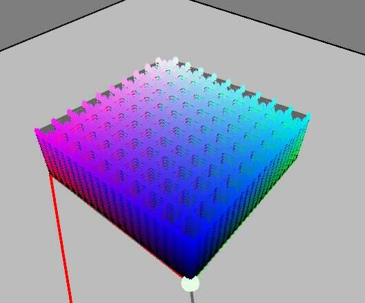
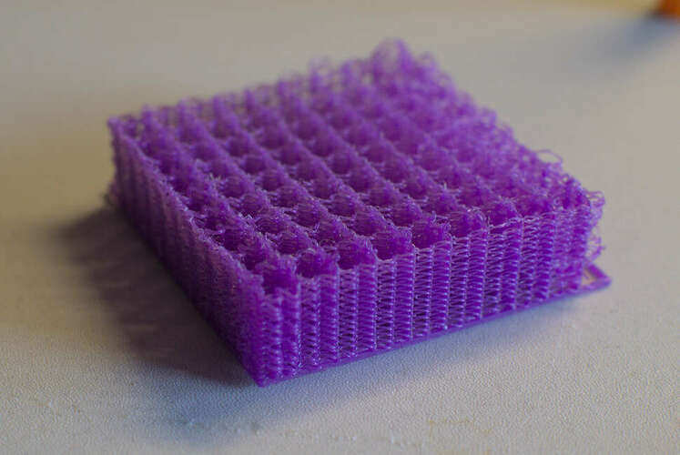
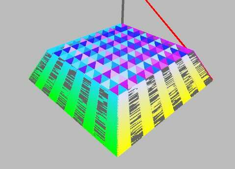 |
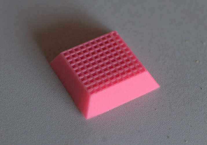 |
|---|---|
| This code resulted in half a pyramid | The printed result |
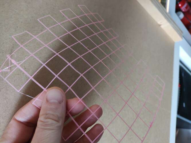
Although at first it looked like nothing you couldn’t make with a mesh and a slicer, this object had a cool property: the openings in the grid were diagonal, which meant you can only see light pass through if you hold the object at a certain angle.
| Tilting the object makes for a cool effect |
I was happy with the result and ready for more.
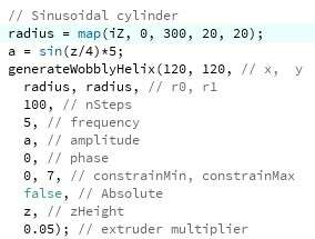
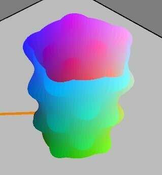
Circular objects are quite stable so I made a function to create a spiral. Eventually I extended the function to make a spiral with a sine-wave superimposed, so I could make wobbly surfaces.
void generateWobblyHelix(float centerX, float centerY,  // center of the spiral
    float radius0, float radius1, // start and end radius
    int nSteps, // Amount of steps to approximate
    float frequency, float amplitude, float phase, // parameters for the superimposed sine wave
    float constrainMin, float constrainMax, // truncate values for the sine wave
    boolean absolute,  // sine wave absolute or not
    float zHeight, float flowRate) {

  // Use polar coordinates for the helix
  float x, y, fi, radius, sineOffset;
  for (int iStep=0; iStep<nSteps; iStep++) {
    fi = (float)iStep/nSteps * 2 * PI;
    radius = map(iStep, 0, nSteps, radius0, radius1);
    // Superimpose the sinewave
    sineOffset = sin(frequency * fi + phase);
    sineOffset = absolute ? abs(sineOffset) : sineOffset;
    sineOffset *= amplitude;
    sineOffset = constrain(sineOffset, constrainMin, constrainMax);
    radius += sineOffset;

    x = centerX + radius * cos(fi);
    y = centerY + radius * sin(fi);

    // add the gcode command to the list
    gcode.addCommand(new PrintCommand(new PVector(x, y, zHeight), flowRate));
  }
}
| In this interactive demo you can see the effects of the helix function | Drag the sliders to see the effects. |
|---|---|
Generating a stack of these helices with the following code:
for (int iZ=0; iZ<nLayers; iZ++) {

    float shrinkage = iZ*0.1;
    float z = 0.1 + iZ*0.2;

    // WobblyCylinder
    generateWobblyHelix(120, 120,  //center
        20, 20, // radii
        100, // steps
        1+shrinkage/7, 2, -shrinkage/7, // sine parameters
        -100, 100, // unconstrained
        false, // not absolute
        z, 0.05); // z and flowrate
}
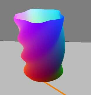 |
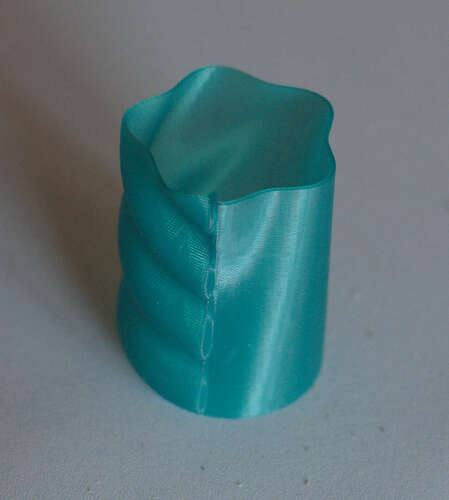 |
|---|---|
| The code generated a kind of wobbly cylinder… | …which looked like this when printed. |
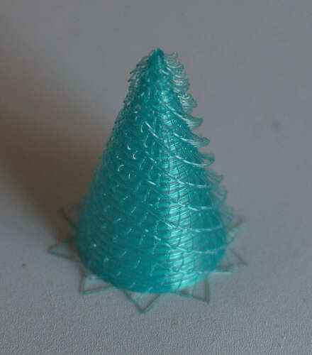
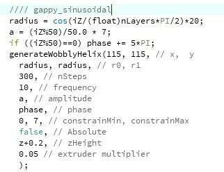
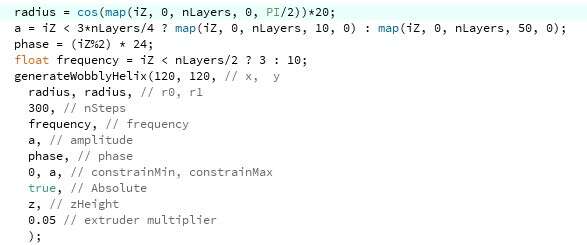
Then I proceeded to experiment with out-of-perimeter printing. This can be done by periodically have deviations from regular the perimeter of the cylinder.
// consider this code to be in a for-loop with increasing iZ and z
// XMasTree
float radius = map(iZ, 0, nLayers, 20, 1);
if (iZ % 10 == 0) { // change the superimposed sine wave parameters for every 10 layers
 generateWobblyHelix(120, 120, radius + 7, radius + 7, 100, 5, -7, shrinkage, -5, 5, true, z, 0.05);
} else {
 generateWobblyHelix(120, 120, radius, radius, 100, 0, 0, 0, 0, 0, true, z, 0.05);
}
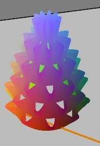
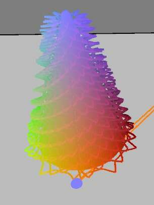 |
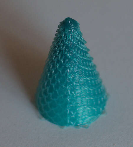 |
|---|---|
| This resulted in an object resembling an xMas tree | Having a roll of green PLA loaded was a total coincidence |
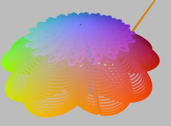
Although it was quite my intention to have it look a little messy, I observed way too much material being extruded at the top of the cone shape. To investigate further I decided to print a simple cone shape and see what went wrong.
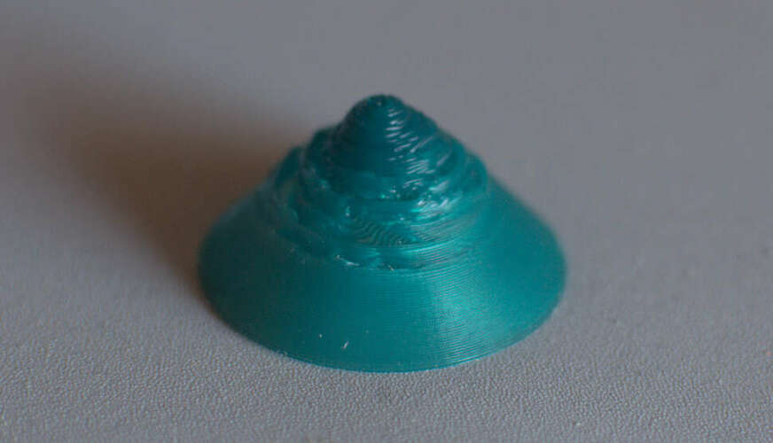 |
|---|
| The cone got really messy |
It seemed too much material was extruded approaching the top of the shape. I didn’t experience this problem with earlier tests though.
| Extrusion depends on travel length |
|---|
Again this came down to misinterpretation of the E parameter. Whatever comes after E is the amount of extruded material for the execution of that particular command. Because the radius of the cone is way smaller at the top, but the same number of commands are used to describe its circle, the printer tried to extrude the same amount of plastic for a small circle at the top as for a big circle at the bottom. I would eventually have had this same problem with my stacked grid pyramid. The problem could be solved to make the E parameter depend on the length of the path of the printhead. The parameter in my code would then act as a multiplier |
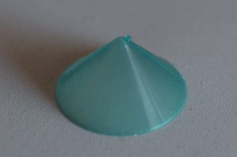 |
|---|
| Solving this gave me a very nicely extruded cone. |
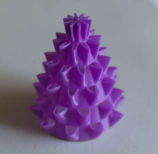
 |
|---|
| The xMas tree looked way better as well |
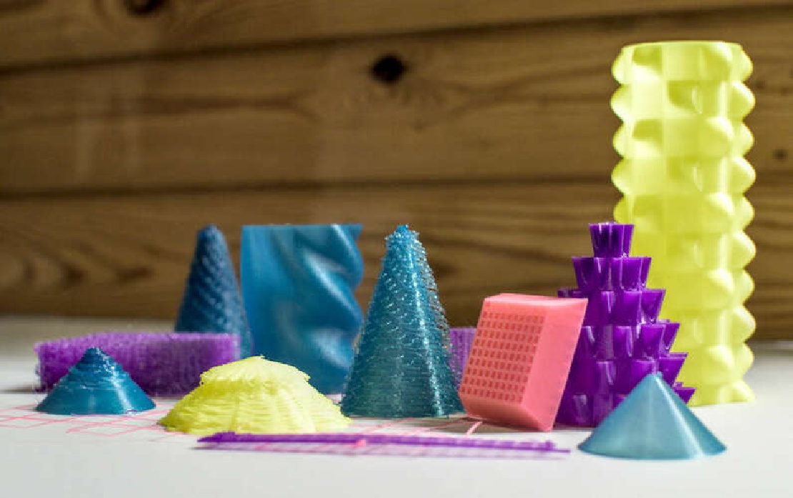
| Code | Processing shape | 3d print |
|---|---|---|
 |
 |
 |
 |
 |
 |
 |
 |
 |
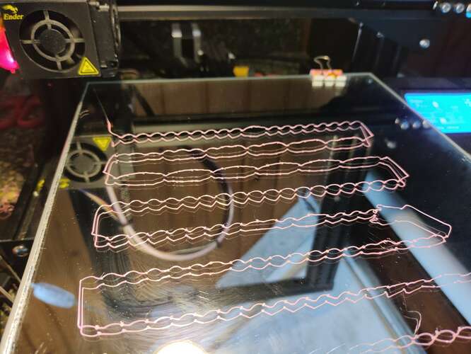
After being successful in printing strange objects it was time to revisit non-planar printing. I’m really interested in prints where the printhead makes hopping motions in the z direction. If a printed line could have little, reproducible arcs of plastic, it would allow for prints that use less material and be more flexible.
As with the first attempt I used an absolute sine-wave to make the print-head “hop” in the z-direction. A gcode generator function called generateHoppyCircle was used to create gcode for a circle with a preset amount of “hops” in the z-direction. The function first creates a flat circle for support, followed by a circle for which the z-axis hops up and down.
The first attempt failed.
| The z-axis hops but rips off the first layer. | Putting down at least 5 layers underneath makes the structure stable enough. |
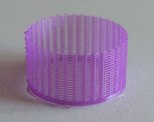
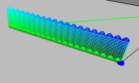
After solving the bed-adhesion problem, the gcode actually created a sparse cylinder.
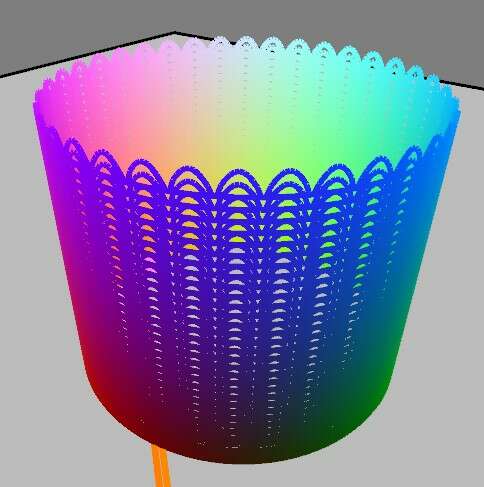 |
 |
|---|---|
| A “hoppy-cylinder” in processing | The printed result |
| The resulting cylinder was way more flexible that it would have been without the hopping. |
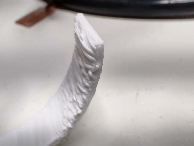
The printed arcs weren’t quite as high as they were designed to be in processing.
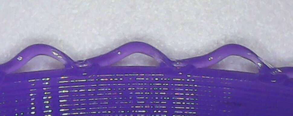 |
|---|
| Looking at the structure under a microscope, I could determine that the actual shape of the “hop” is reproducible, but no arc at all. |
To actually make little arcs I will have to play with the hopHeight, the flowRate, the temperature and the hopDistance. Furthermore, I would probably need to know how to retract material to stop if from oozing when the flowRate is set lower momentarily. This would take too much time, so I continued with my suboptimal hops.
 |
 |
|---|---|
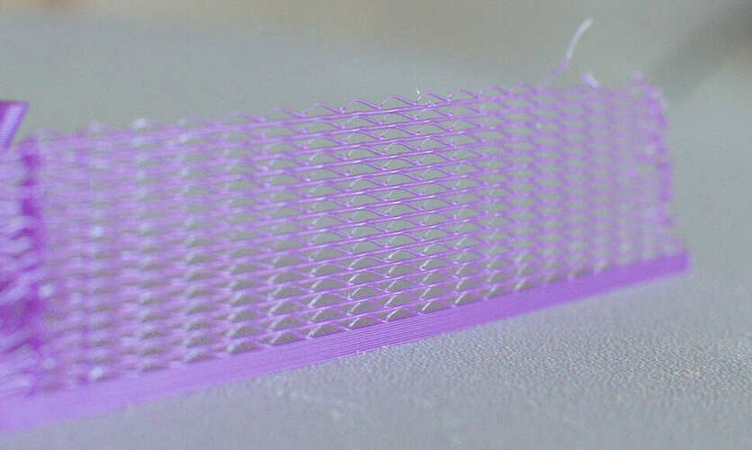
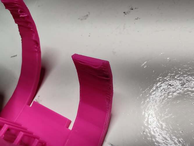
Using the function generateHoppyLine I stacked multiple arcs on top of each other to make a sparse vertical wall. |
At the turns, the result is a bit messy because the hops didn’t connect to the supporting surface very well. |
The result was very flexible, although a bit prone to breaking.
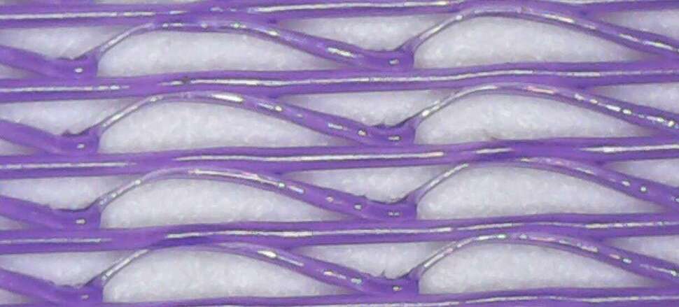 |
|---|
Under the microscope it was very clear that the hops were asymmetrical. This might be corrected by using something other than abs(sin) to generate the hops. Perhaps using splines. |
Of course there is no sense in creating 2D structures in the Z direction. Such a structure could be easily replicated in the XY-plane. The ultimate application would be to make a very sparse but strong and maybe flexible kind of infill material. To test this out I made a “hoppyGrid” and stacked multiple of those structures on top of each other to generate a sparse 3d structure.
 |
 |
|---|---|
| The “hoppy-grid in Processing | The printed result |
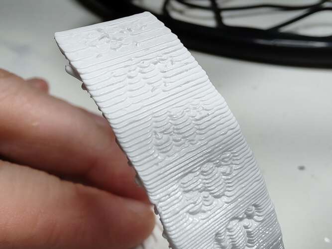
The result was not as flexible as I hoped, but surprisingly light for its appearance.
 |
|---|
| Under the microscope the result was pretty messy. |
Because the printer is not designed for non-planar printing the hot-end got in the way of already printed structures, remelting them and making a bit of a mess. Still, the properties of the resulting material were quite different from what more traditional methods would yield. Lighter and slightly more flexible.
There is a lot more to research for such structures. Some ideas for future expansion and enhancement:
Scanning 3d objects and people at the Waag is done with the 3d Systems “Sense” scanner.
| It uses two RGB cameras and some image processing to compute the depth of objects in it’s field of view. " |
|---|
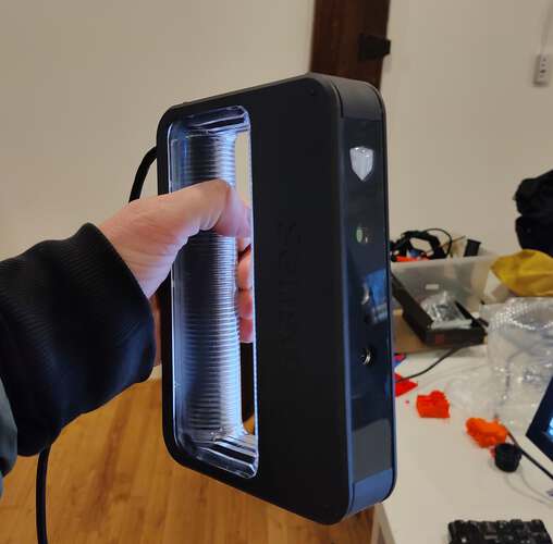 |
This method has some limitations:
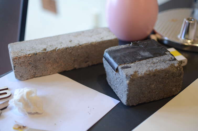
Ideal objects to be scanned have lots of geometrical and textural features. I have tried to scan a:
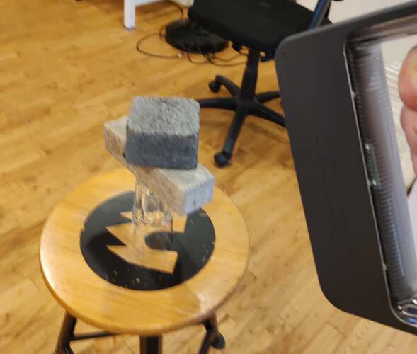
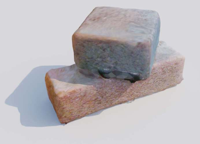
Eventually I settled on scanning some bricks.
| These bricks were lying around in the lab to be used for flattening sheet material in the lasercutter. | The material properties of the bricks made them ideal for scanning. Not too dark, not too shiny |
|---|---|
 |
 |
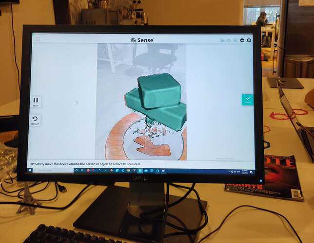
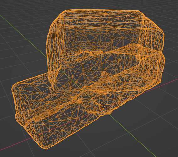
The bricks came out pretty well. The scanner software allowed me to save the result as an OBJ file and therefore could include the textures and texture mapping information.
| The result in the “Sense” software | The polygon count is very high. |
|---|---|
 |
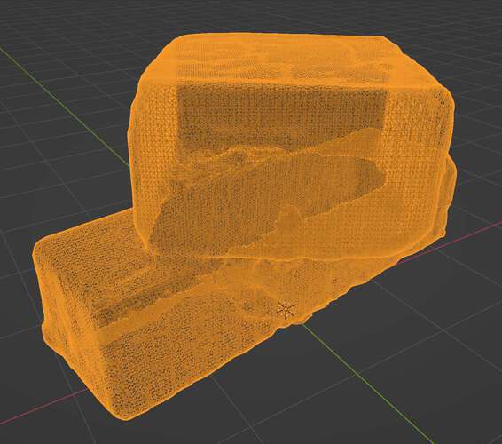 |
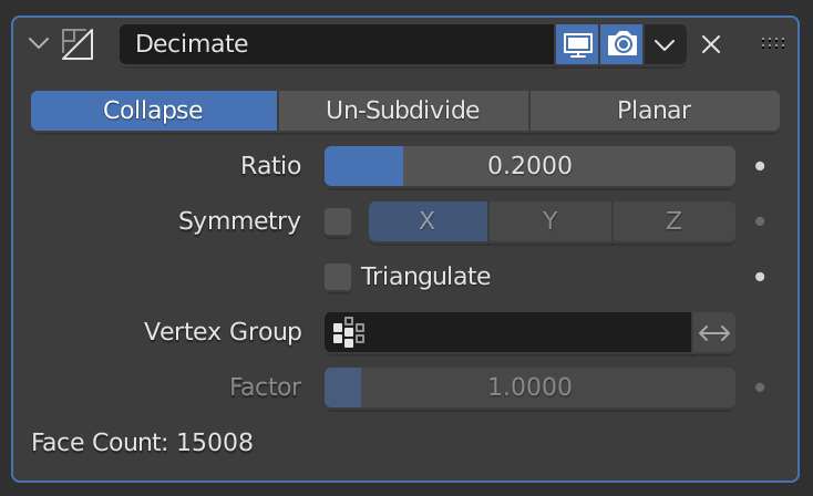
Using the decimate modifier… |
…the polygon count was greatly reduced. |
|---|---|
 |
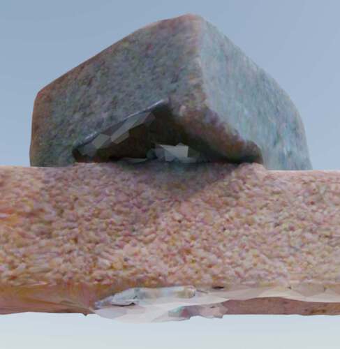
 |
| The bricks, textured and rendered in Cycles on a sunny day | A shiny piece of tape and the surface of contact with the glass the bricks were on, were not correctly scanned |
|---|---|
 |
 |
I must admit there is not much sense in scanning bricks, but I liked doing it to experience the 3d scanning workflow. There was little sense in having a dense model of two stacked bricks, but still I decided to have some fun with them.
| Using the bricks as a blender soft body object and a plane as a collider |
|---|
If the video doesn’t work: watch on youtube.
I set out to experiment with generating my own gcode and I was quite happy it turned out the way it did. Slicers are very complex pieces of software but with limited time and effort, it is entirely possible to create 3d-printed objects from scratch. With just a few parameters. I was actually amazed it was as accessible as it was. I performed a lot of experiments. To review my goals from the start:
It worked. I programmed Processing/Java functions and classes to do just that.
Make objects with generated gcode that would be hard to make with conventional slicing methods:
Quick mathematical shapes
Using sinusoidal functions it’s possible to generate a wide range of interesting structures. Printing such a structure is fairly quick as it doesn’t need support structure. Mostly7 it is just one wall thick. The largest object took 1 hour to print.
Infill patterns are mostly generated without taking the shape of the object into account. By stacking the grids and shrinking the infill pattern as a function of the height, I managed to make the infill pattern a bit more interesting.
By making the z-axis “hop” I could make sparse structures.
Using different parameters for single layers of a sinusoidal shape, I managed to make something that resembles an xmas-tree. Strange surface properties can be had when you don’t care about nice layer adhesion.
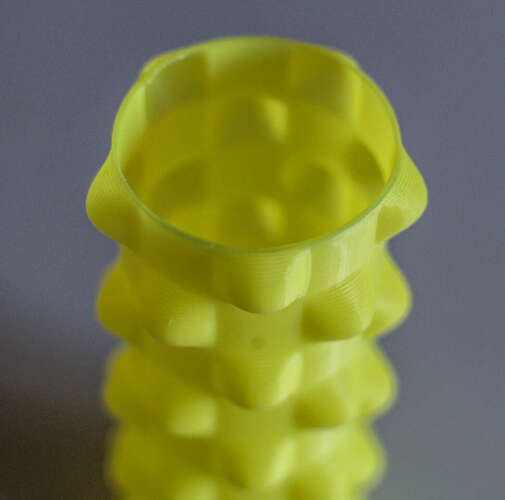
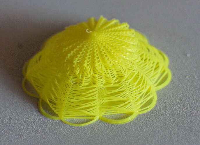
The yellow flower was an experiment in shifting layers. If this is done too much, layer adhesion is so low, the material has a hard time keeping it’s shape in the xy-plane.
We found a test model on Thingiverse that could be used to determine how wel a printer performs. We tested the print on two different printers, the ultimaker 2+ and the Prusa i3 MK3. Both models were sliced with the default settings for both printers at medium quality. The model for the Prusa was sliced using Prusa Slicer and the model for the ultimaker was sliced using Cura.
| Prusa i3 MK3 | Ultimaker 2+ |
|---|---|
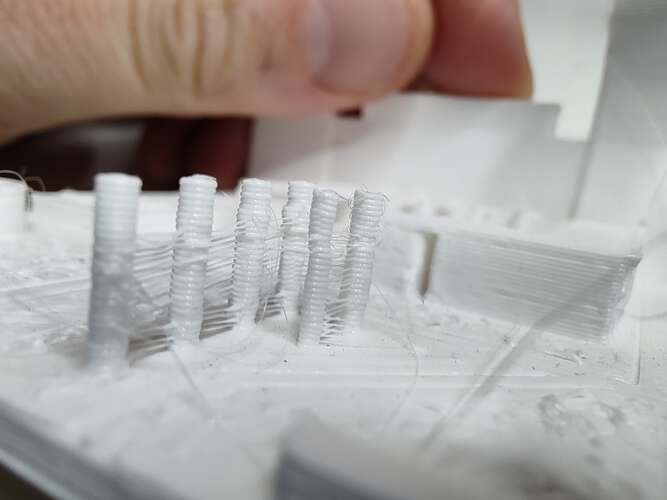 |
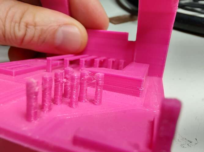 |
The Prusa i3 MK3 displays more stringing in the region where multiple pillars have to be printed.
| Prusa i3 MK3 | Ultimaker 2+ |
|---|---|
 |
 |
 |
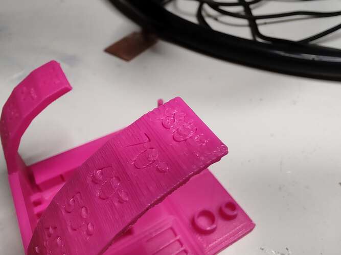 |
It seems the default setting for the Prusa have larger layer heights. The details in the numbers on the models were hardly readable. The Ultimaker didn’t have much trouble with that.
On the bottom side of the overhangs, the Prusa displayed more sagging.
| Prusa i3 MK3 | Ultimaker 2+ |
|---|---|
 |
 |
 |
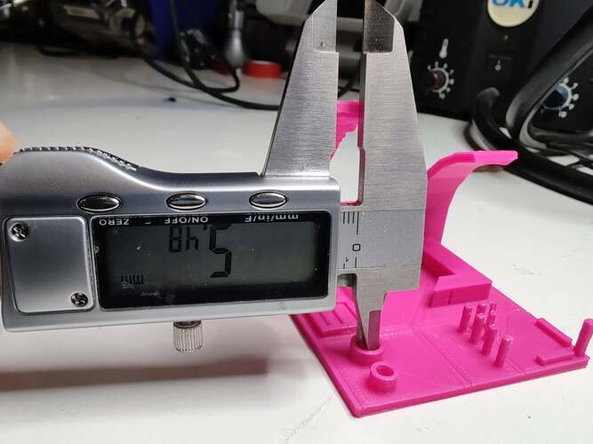 |
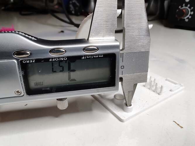
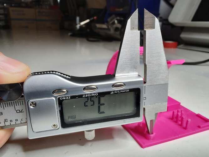
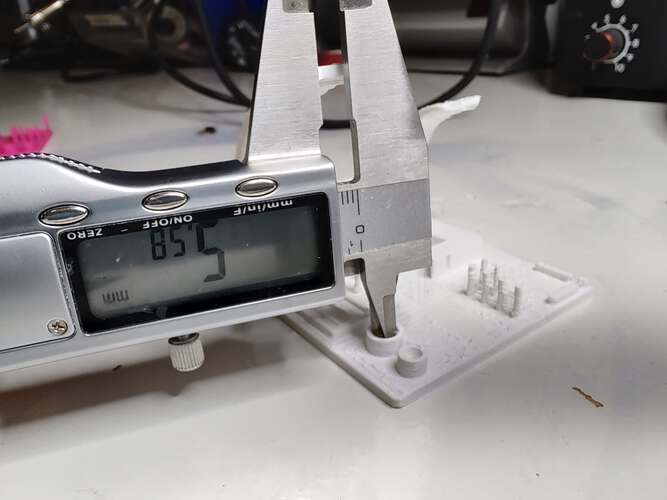
The size of 3d prints always have a slight deviation from the actual model. Two vertical holes in the model can be used to determine the expansion or contraction of the prints. The small hole should be 3mm and the large hole should be 5mm. Both holes were printed larger than the model would dictate. The expansion of the Prusa was slightly larger than that of the Ultimaker. Horizontal expansion is a setting in Ultimaker Cura to compensate for this effect.
Final project Initial conception (Febuary 2022) Learning to play any musical instrument takes a very long time and a lot of effort. To enjoy music …
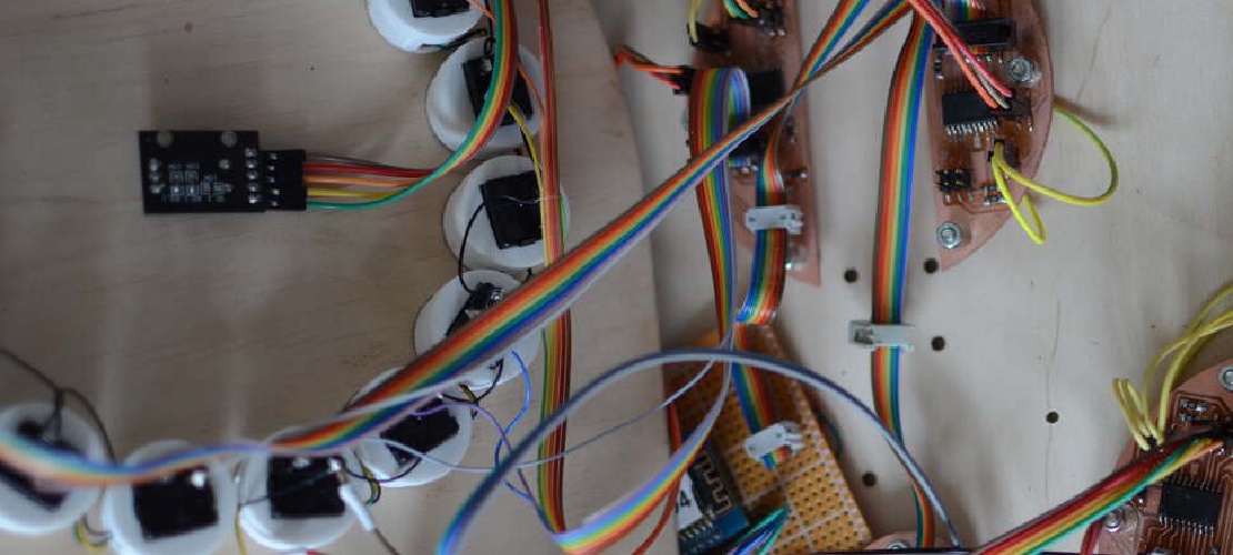
What I did. I created the enclosure and designed and milled all the PCBs. TODO Hardware Priority 1 20 x Button LED caps 8x Octave1 8x Octave2 4x chord …