9. Embedded Programming
This week we started working on embedded programming. As a software developer I have a lot of experience working with different programming languages, but I admit I had to refresh my memory on C programming since I haven’t programmed in that language for a while.  Also, as a group assignment we had to review development workflows using different architectures. In my case, I was in charge of reviewing the Raspberry pi development workflow.
Checklist:
- Document what you learned from reading a microcontroller datasheet.
- Program your board.
- Describe the programming processes you used.
- Include your source code.
- Include a short ‘hero video’ of your board.
Group Assignment
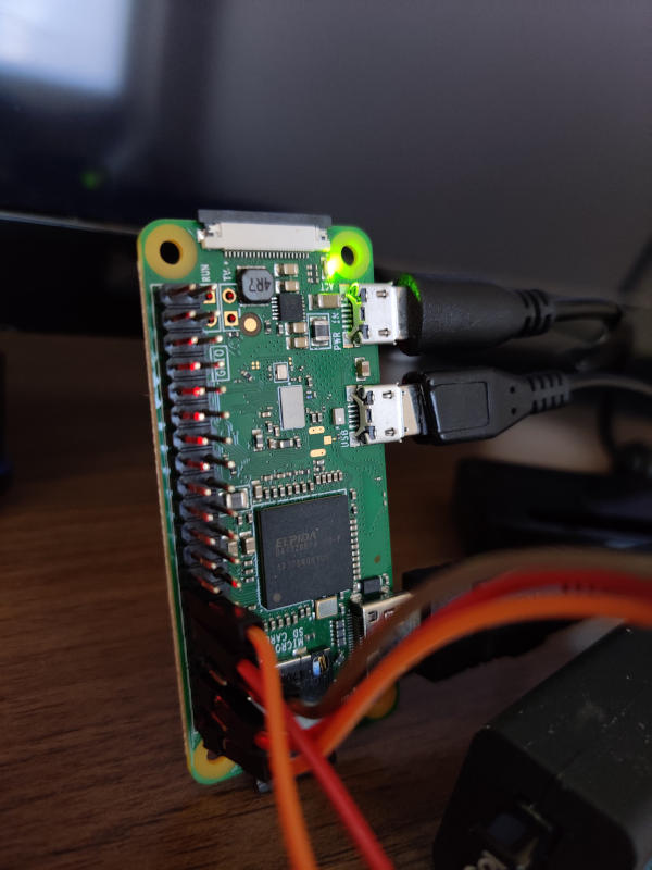
We tested the Raspberry pi development workflow, since I have a Rasperry PI Zero W from the project I mentioned in my About page. The simplest way to do it would be blinking leds, unfortunately I didn’t have leds available when I was running the test, so we used a couple of sensors I had available from the same project I mentioned.
Raspberry Pi Zero W Specification:
- 802.11 b/g/n wireless LAN
- Bluetooth 4.1
- Bluetooth Low Energy (BLE)
- 1GHz, single-core CPU
- 512MB RAM
- Mini HDMI port and micro USB On-The-Go (OTG) port
- Micro USB power
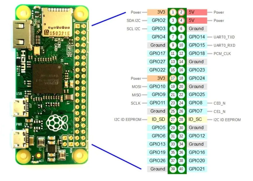
- HAT-compatible 40-pin header
- Composite video and reset headers
- CSI camera connector
In order to start using the raspberry board we had to connect the following things:
- A SD card with raspbian installed.
- A power supply.
- A usb hub.
- A display on the HDMI port.
Once the board had turned on and the Raspbian OS had started, we proceeded to connect the sensors and write python scripts to get data from them:
Door Sensor
We wrote the following script to get data from the Door Sensor:
import RPi.GPIO as GPIO
import time
import sys
import signal

GPIO.setmode(GPIO.BCM)

DOOR_SENSOR_PIN = 18

isOpen = None
oldIsOpen = None

GPIO.setup(DOOR_SENSOR_PIN, GPIO.IN, pull_up_down = GPIO.PUD_UP)

while True:
    oldIsOpen = isOpen
    isOpen = GPIO.input(DOOR_SENSOR_PIN)
    if(isOpen and (isOpen != oldIsOpen)):
        print "Door is open"
    elif (isOpen != oldIsOpen):
        print "Door is closed"
    time.sleep(0.1)
As you can notice, we connected the door sensor to the pin 18. So our code reads the status of this pin to show a message.
PIR Sensor
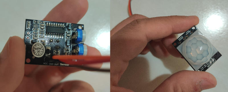
We also tested a PIR sensor. This sensor has 3 pins: VCC, OUT and GND. We connected the OUT pin to pin number 4 in the raspberry board. Then we wrote the following piece of code:
from gpiozero import MotionSensor

pir = MotionSensor(4)
count = 0

while True:
        pir.wait_for_motion()
        count += 1
        print("Intruder Alert!")
        pir.wait_for_no_motion()
Conclusions
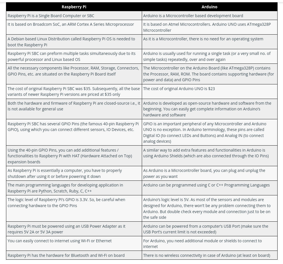
Raspberry Pi is a Microprocessor (usually an ARM Cortex A Series) based board that acts as a computer. It can run an Operating System. The Raspberry Pi Foundation provides a Debian based Linux Distribution called the Raspberry Pi OS (previously known as the Raspbian OS). You can develop software using several Programming Languages like C, C++, Python, Java, HTML, etc.
This board gives you enough flexibility in terms of programming languages. It is also powerful enough to deploy complex applications, including web applications. However since it is ARM based, there are some packages that are not supported yet.
Individual Assignment
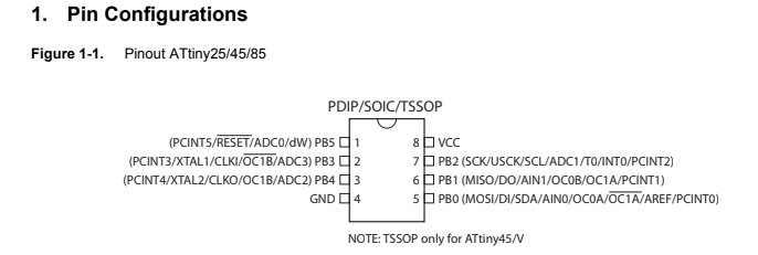
Attiny 45 Datasheet
After reading the Attiny 45 Datasheet I extracted the following important information:
The ATtiny25/45/85 is a low-power CMOS 8-bit microcontroller based on the AVR enhanced
RISC architecture. By executing powerful instructions in a single clock cycle, the ATtiny25/45/85
achieves throughputs approaching 1 MIPS per MHz allowing the system designer to optimize
power consumption versus processing speed.
Programming
I decided to continue using the board I fabricated weeks ago. It is a really simple board, since it basically consists in:
- An Attiny 45 microcontroller
- A led
- A Button
- A FTDI connector
I wanted to use the button on that board to trigger events on my computer through the serial connection. I checked the hello.ftdi.45.echo code programmed by Neil and it seemed too complex for me first. I though I could use Serial command in arduino but I got the following error:
error: 'Serial' was not declared in this scope
It turns out that our attiny microcontroller do not have direct support for hardware based serial and therefore the Serial object was unavailable in our code, however, it could be solved by including SoftwareSerial.h just like Neil did in hello.ftdi.45.echo.serial. The only downside of this method is that it consumes a lot of memory on the microcontroller, for that reason I decided to continue using parts of the hello.ftdi.45.echo code.
I ended up combining Neil’s hello.ftdi.45.echo with the pushbutton code I used a few weeks ago to test this board:
const int BUTTON = 4;
const int LED = 3;
int BUTTONstate = 0;

void setup() {
   //
   // set clock divider to /1
   //
   CLKPR = (1 << CLKPCE);
   CLKPR = (0 << CLKPS3) | (0 << CLKPS2) | (0 << CLKPS1) | (0 << CLKPS0);

   //
   // initialize pins
   //
   set(serial_port,serial_pin_out);
   output(serial_direction,serial_pin_out);
   pinMode(BUTTON, INPUT_PULLUP);
   pinMode(LED, OUTPUT);

   }

void loop() {

  BUTTONstate = digitalRead(BUTTON);
  if (BUTTONstate == HIGH)
  {
    digitalWrite(LED, HIGH);
    put_string(&serial_port,serial_pin_out,"1 \n");

  }
  else{
    digitalWrite(LED, LOW);
  }

}
The above code turns on the led in the board and sends data via the serial port when the button is pressed. Then I had to do something with the data sent from the board. I didn’t want to just show data in the serial monitor… I wanted to trigger some kind of event or use my board as a keyboard to control things, like in a videogame. The keyboard command in arduino allows your board to be used as a usb keyboard, unfortunately the attiny doesn’t support this either.
I came across the Web Serial API, which allows websites to communicate with serial devices. Here’s a short guide on how to use it. I figured out that I coud use this API to control games in the browser using my board, so I went to https://chromedino.com/ and started to think how to control the dinosaur with my board.
I created the following snippet for adding a button to https://chromedino.com/ for connecting the website with my board:
function insertAfter(newNode, existingNode) {
    existingNode.parentNode.insertBefore(newNode, existingNode.nextSibling);
}

const setup = async()=>{
    const port = await navigator.serial.requestPort();
    await port.open({
        baudRate: 9600
    });
    let decoder = new TextDecoderStream();
    inputDone = port.readable.pipeTo(decoder.writable);
    inputStream = decoder.readable;
    reader = inputStream.getReader();

    while (true) {
        const {value, done} = await reader.read();
        if (value) {
            console.log("value, done", value, done);

            Podium = {};
            var n = document.createEvent("KeyboardEvent");
            Object.defineProperty(n, "keyCode", {
                get: function() {
                    return this.keyCodeVal;
                },
            }),
            n.initKeyboardEvent ? n.initKeyboardEvent("keydown", !0, !0, document.defaultView, 32, 32, "", "", !1, "") : n.initKeyEvent("keydown", !0, !0, document.defaultView, !1, !1, !1, !1, 32, 0),
            (n.keyCodeVal = 32),
            document.body.dispatchEvent(n);

        }
        if (done) {
            console.log('[readLoop] DONE', done);
            reader.releaseLock();
            break;
        }
    }

}

let btn = document.createElement("button");
btn.innerHTML = "CONNECT";
btn.onclick = setup;

let runner = document.getElementById('main-content');

insertAfter(btn,  runner);
To run this code:
- Connect your board.
- Program it to send data through serial port when pressing the button.
- Open google chrome
- Go to https://chromedino.com/
- Open developer tools (press F12)
- Go to the ‘Sources’ tab
- Add a new snippet and paste the code above.
- Execute the snippet (ctrl + Enter)
- A “connect” button should appear next to the game canvas.
- Press the connect button and select the serial device.
- Press the button in your board and start the game.