7. Electronics Design
During this week we learned the basics of electronics designs. We reviewed some of the most common electronic components and how to place them on circuits. Finally we also reviewed the most common test equiment for electronics (You can find more details on our group assignment’s page)
For this week’s individual project we should:
- redraw an echo hello-world board,
- add (at least) a button and LED (with current-limiting resistor)
- check the design rules, make it, and test that it can communicate
Checklist:
- Link to the group assignment page.
- Document what you have learned in electronics design
- Explain problems and how you fixed them, if you make a board and it doesn’t work; fix the board (with jumper wires, etc) until it does work.
- Include your original design files.
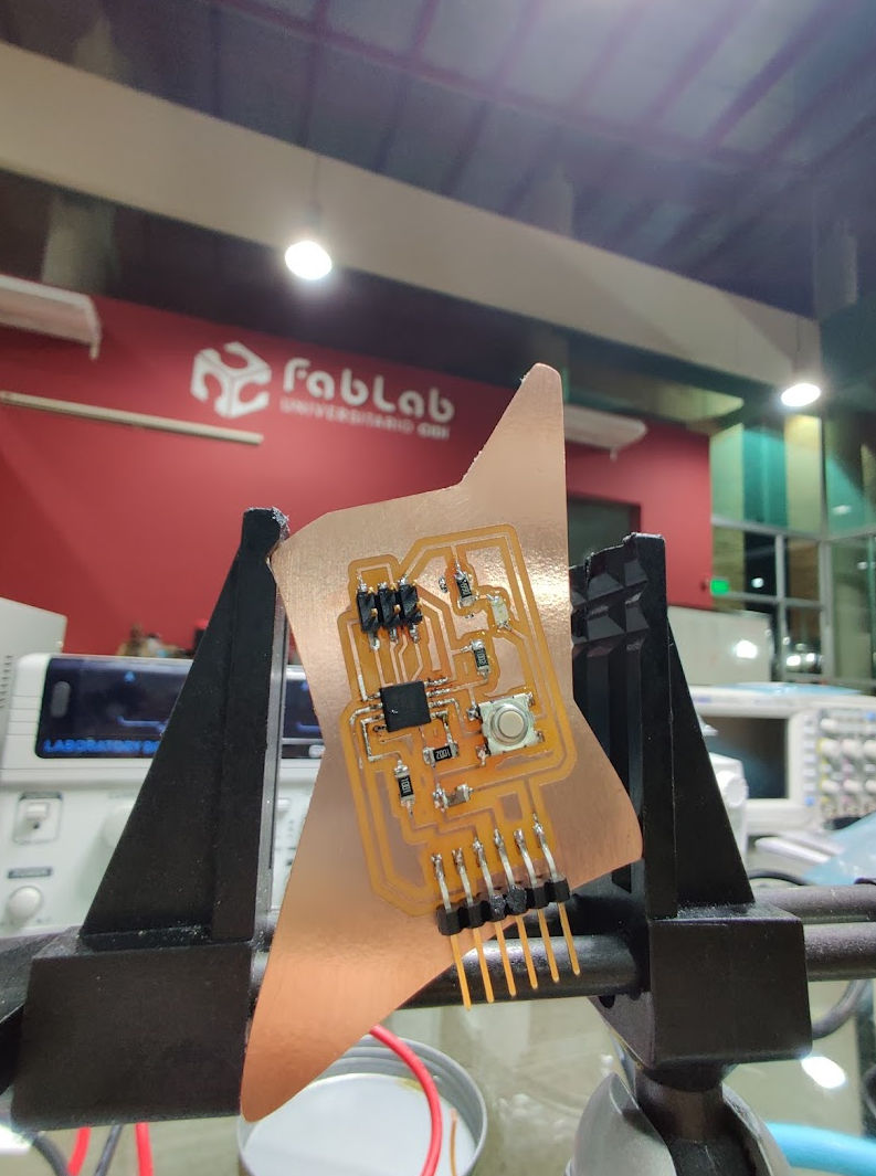
- Include a ‘hero shot’ of your board.
- Load a program and tested if yourboard works.
Test Equipment in our lab
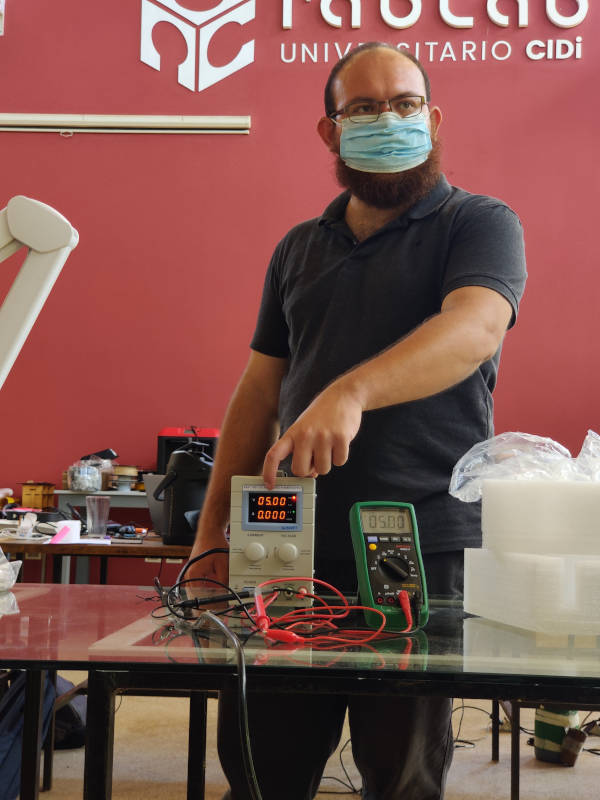
As part of our group assignment, Abdón - our local instructor - showed us the following test equipment:
- Multimeter: handheld device used to measure electrical voltage, current (amperage), resistance, and even other values like temperature. You can also test diodes and check continuity of any circuit. It is commonly used for troubleshooting electrical problems on circuits, motors, appliances. It has two leads —red and black — and three ports. The black lead plugs into the “common” port. The red lead plugs into either of the other ports, depending on the desired function.
- Regulated Power Supply: It converts unregulated AC (Alternating Current) to a constant DC (Direct Current). A regulated power supply is used to ensure that the output remains constant even if the input changes.
- Function generator: It is a device that generates different types of electrical waveforms over a wide range of frequencies. Including: sine wave, square wave, triangular wave and sawtooth shapes. Function generators are used in the development, test and repair of electronic equipment.
- Osciloscope: It helps you to visualize an electrical signal as it varies over time. Commonly: time is on the x-axis and voltage is on the y-axis of the generated 2D graph.
Additionally, as a general rule always be sure to check the voltage before connecting and turning on any of these devices.
Choosing a Base Design
Considering the components available in our lab, our instructors reccomended we use the ATtiny45 board in the assignment resources as a base design.
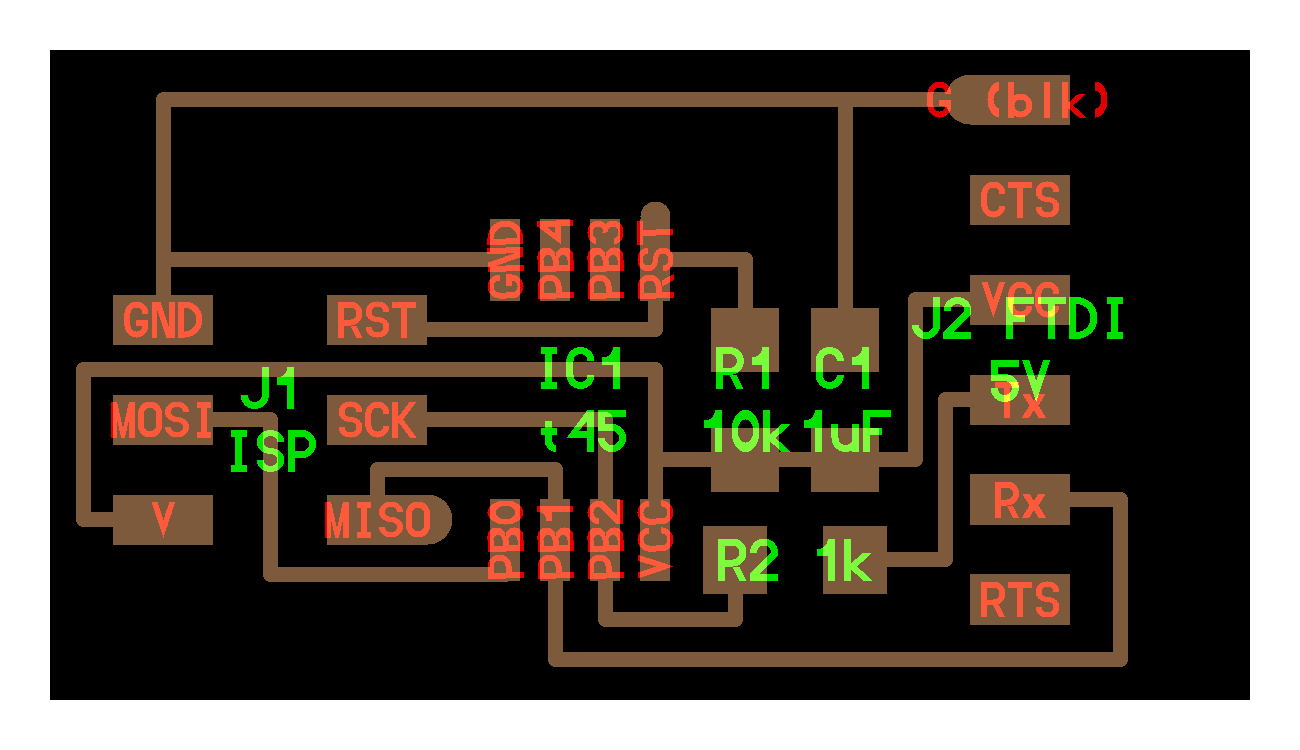
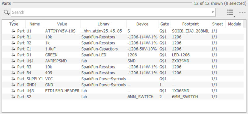
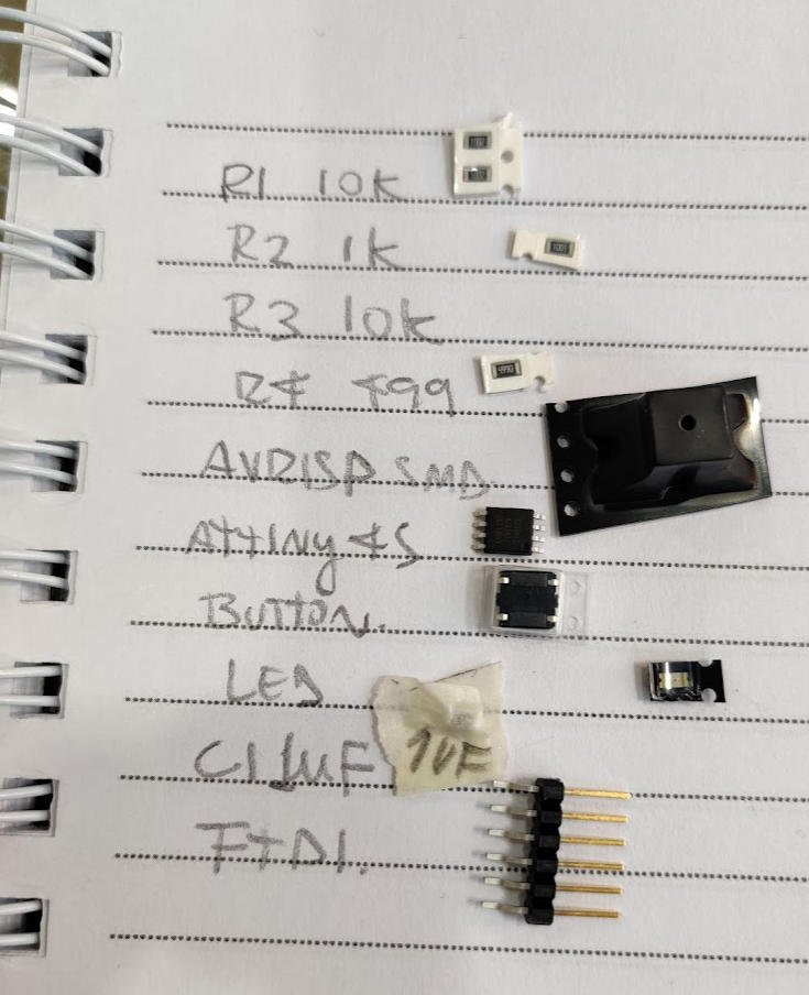
Components used in this board:
- ISP Connector.
- ATtiny45
- 1k Resistor
- 10k Resistor
- 1uF Capacitor
- FTDI Connector
Setting up environment.
Abdón recorded a video showing how to install, configure and use Eagle. The video is available on his Youtube channel. In order to start using Eagle I followed these steps:
- Install Eagle from autodesk’s website.
- Download Sparkfun-Eagle-Libraries from this github page and follow the intructions described in both the readme file and the sparkfun site.
- Select download zip option in the gihub page. Then extract the file in a dedicated directory in your computer.
- Go to Eagle,
Options > Directoriesand add the path to the extracted file. - Enable the sparkfun libraries in the Libraries tree by right clicking the library an selecting the
Use alloption.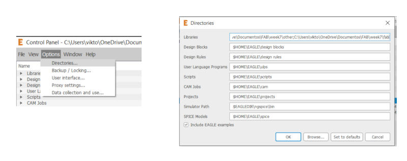
Adding library directory - Additionaly, I decided to include this version of the fab components library because it contains components for the same FTDI SMD headers, AVR ISP-6pin Headers, 6mm switch.
- The attiny45 component is not present in the libraries mentioned above, but there is a component for the attiny85 which (according to this datasheet) is equivalent to the attiny45. For this reason most of my classmates decided to go with the atttiny85 component. However, I continued searching for the exact ATtiny45 component (just for fun) and used it instead.
Designing the schematic and board.
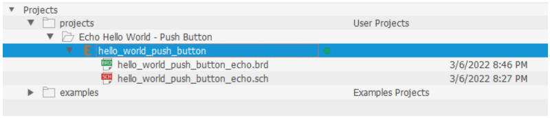
Following the instructions in Abdon’s video, I created a project called hello_world_push_button and added the corresponding board (.brd) and schematics (.sch) files.
I started adding all the necessary components that are shown in the base board design available in the fab site. As I mentioned before, some components are part of the Sparkfun library, some other are part of the fab library and the microcontroller is part of the hhn_attiny25_45_85_r500 library that I’ve found.
Additionally a button, a led and a pair of resistors were added in order to complete this week’s task. I followed this guide to understand how these components work.
Once all the components were added to the schematic, I proceeded to create relations between them by using the Net tool and following the base design.
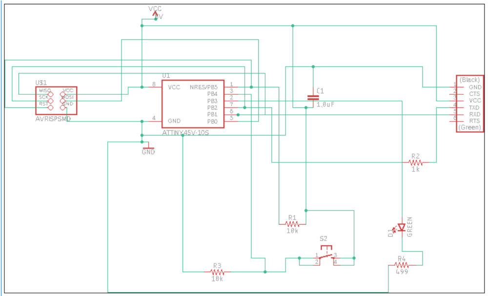
Then I switched to the board view to start moving the components and creating the traces. There are many factors to take into account when calculating the width of the traces, but Abdón recommended using a trace width of 0.5 mm (0.020 inch). I used that width in most parts of my board, however I had to reduce the width to 0.4mm (0.016 inch) to draw the traces located below the microcontroller.
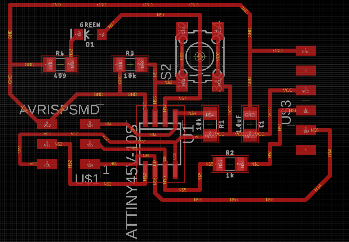
Finally I clicked on the CAM processor icon to export the board to a gerber file.
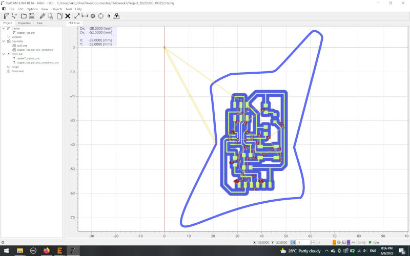
Milling the board
Time to open FlatCAM and import the gerber file. Like last time, I used 1/64 inch endmill for the traces and the 1/32 for the cutout.
This time I wanted to use a custom design for the cutout, so I opened Inkscape and tried to draw the shape of a Gibson Explorer guitar.
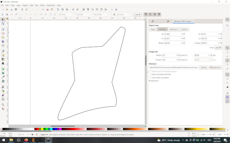
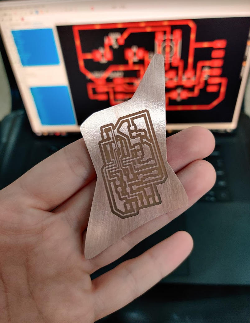
Then, I saved this file as a SVG, imported it into FlatCAM and generated the CNC jobs for both the traces and this cutout.
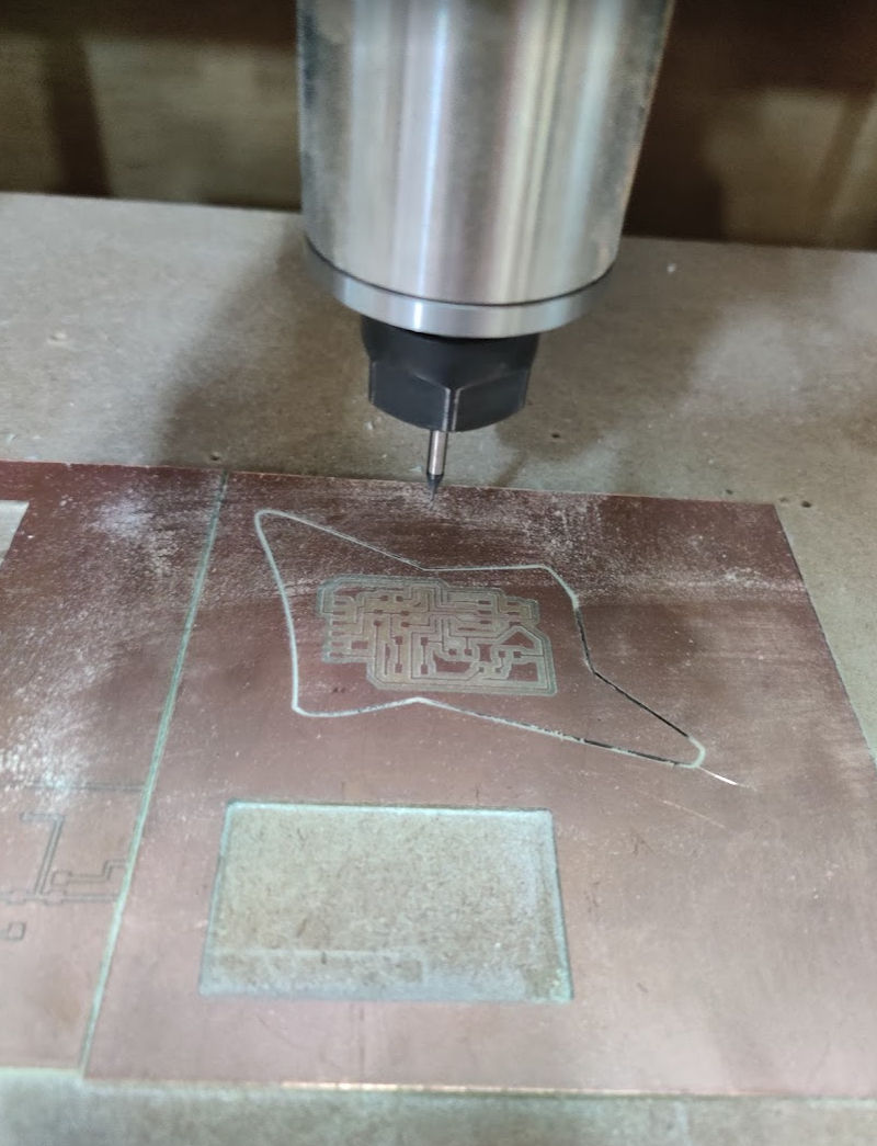
Then I proceeded to mill the board in our Roland MODELA PRO II MDX-540
Stuffing the board
After cleaning the board with steel wool, and placing all the tools and components next to me I started to solder them into the board.
This time, I didn’t make the mistakes of the last time. (I didn’t lose or break any components and didn’t tear traces)
Programming the board
I used the FabISP I previously prepared to program the board. In order to use it in ArduinoIDE, I had to set up some preferences first.
- To add new boards to Arduino’s Board Manager, first go to File > Preferences and paste the following string in Additional Boards Manager URLs:
https://raw.githubusercontent.com/damellis/attiny/ide-1.6.x-boards-manager/package_damellis_attiny_index.json. Additionaly, tick the compilation and upload options in the “show verbose output during” section for better debugging.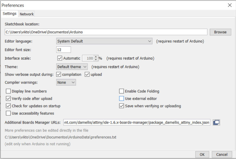
Arduino preferences - Go to Tools > Boards Manager, type
attinyin the filter box and install the attiny board (by David A. Millis)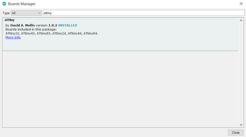
Boards Manager - Connect your board and select the following values:
- Board: ATtiny25/45/85.
- Processor: ATtiny45.
- Programmer: USBTinyISP
- Finally, to program the board write some code in Arduino IDE and then press the verify and upload button.
Surprisingly, the board worked on the first try! Which means that the design, milling and stuffing were correct! Below I describe the programs I loaded into the board to test it:
Blink
I started testing the board by running the hello world version of electronics world: Blinking a Led every 1 second.
void setup() {

  pinMode(3, OUTPUT);       //setting Pin 3 LED as output

}

void loop() {               // ------ Event loop ------ //

  digitalWrite(3, HIGH);    /* Turn on LED bit/pin */
  delay(1000);              /* wait */
  digitalWrite(3, LOW);     /*Turn off LED bit/pin  */
  delay(1000);              /* wait */

}                           /* End event loop */
Pushbutton
Then I continued the tests by implementing the logic for controlling the LED using the button in the board.
const int BUTTON = 4;
const int LED = 3;
int BUTTONstate = 0;

void setup()
{
  pinMode(BUTTON, INPUT_PULLUP);
  pinMode(LED, OUTPUT);
}

void loop()
{
  BUTTONstate = digitalRead(BUTTON);
  if (BUTTONstate == HIGH)
  {
    digitalWrite(LED, HIGH);
  }
  else{
    digitalWrite(LED, LOW);
  }
}
Echo
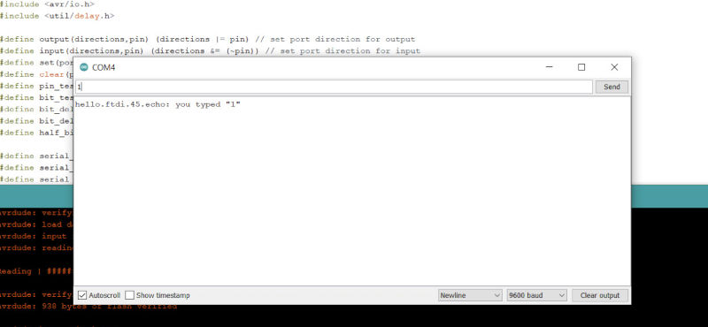
Finally, I tried to run the ECHO code written by Neil. But when I connected to the monitor and wrote a message, the board response seemed to have an encoding problem.
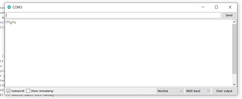
Then I tried modifying the clock frequency from 1Mhz to 8Mhz and the board responded successfully: