11. Output Devices
This week we learned about different devices that could be connected to our boards. Microcontrollers could be programmed to send signals to these devices and control them to perform actions. During this week we had the opportunity to experiment with these devices, in my case I chose experimenting with Electric motors (Specifically Servo motors).
Checklist:
- Link to the group assignment page.
- Document what you learned from interfacing device(s) to microcontroller and controlling the device(s)
- Describe your design and fabrication process or link to previous examples.
- Explain the programming process/es you used.
- Outline problems and how you fixed them.
- Include original design files and code.
- Include a ‘hero shot/video’ of your board.
Selecting Output Devices
Electric motors caught my attention during this week’s global lecture since they could be useful for my final project. So I started the week researching these devices. Below is one of the most comprehensive videos about electric motors:
The Engineering Mindset is another useful youtube channel that I’ve found this week. I spent most part of the week watching their videos about motors, electronics and electricity… They explain many concepts in a very clear way. That’s the reason I highly recommend subscribing to this channel.
I choose Servo motors because of their ability to precisely control the angular position, velocity and acceleration of the motor shaft. I took the following notes:
- When we connect a DC motor to a power supply, it just rotates constantly. But a servo motor doesn’t instantly rotate. Instead, these are sent signals which tell the motor exactly how far to rotate.
- Angles: Typically the motor will rotate just 180 degrees, but we can get smaller or larger values. These are closed loop type. There’s usually a pin inside to physically stop the motor rotating further. Some servo Motors will not have this and are able to rotate the fall of 360 degrees These ones are known as open loop type. Closed loop provides the best control and these are more commonly used.
- Weight value: On the side of the servo motor, we usually find a weight value that represents the torque of the motor or how much force it can apply. We normally find this measured in kilogram centimetres or ounce inches.
- Voltage: The higher the voltage applied, the higher the torque will be, so the stronger the motor will perform. The operating current depends on the load applied as well as the voltage. The motor consumes more power when moving. It uses very little to hold its position. The higher the voltage applied, the faster the motor will rotate.
- Connections: Positive voltage wire, ground and the pulse width modulation signal wires.
- Gears: On the top we find a small splined gear. We can connect various attachments to this to make use of the rotation. The motor has a high rotational speed but a low torque, so the gears help convert this into a low speed but high torque output.
- Feedback: The DC motor is connected to a small circuit board inside the unit. This controls the rotation of the motor as well as the direction of rotation. Also connected to the circuit board is a potentiometer. This connects to the output gear of the servo. This is just a variable resistor. As the final gear rotates, it rotates the potentiometer which changes the resistance and the circuit board reads this to know the position of the output. A controller sends a signal to the servo motor which determines which position it should rotate to. This is a pulse width modulation signal, which means it sends pulses of voltage down the wire. The width of the pulse can be varied. It’s similar to if we pressed a switch to turn the light on and off. The longer we press the switch, the longer the pulse of electricity. These pulses are sent every 20 milliseconds, so we have around 50 pulses per second or 50 Hz. We can use an oscilloscope to see these pulses. The width of the pulse determines the position of the servo. If we send a wide pulse, the servo moves to the left. If we send a small pulse, it rotates to the right. We can move to any position between these two points by simply changing the width of the pulse.
Equipment
After doing some research about Servo motors I selected the a hk15138 servo motor from the fablab’s inventory.
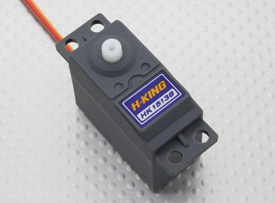
- Torque: 3.8kg @ 4.8v, 4.3kg @ 6v
- Weight: 38g
- Speed: 0.21 / 60deg @4.8v, 0.17 / 60deg @ 6v
- Voltage:4.8v~6v
- Plug: JR Style
Board fabrication
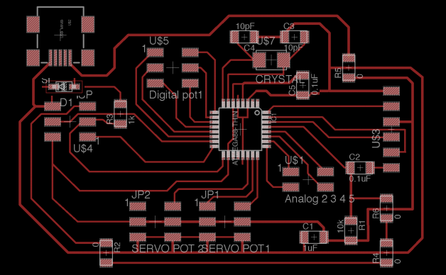
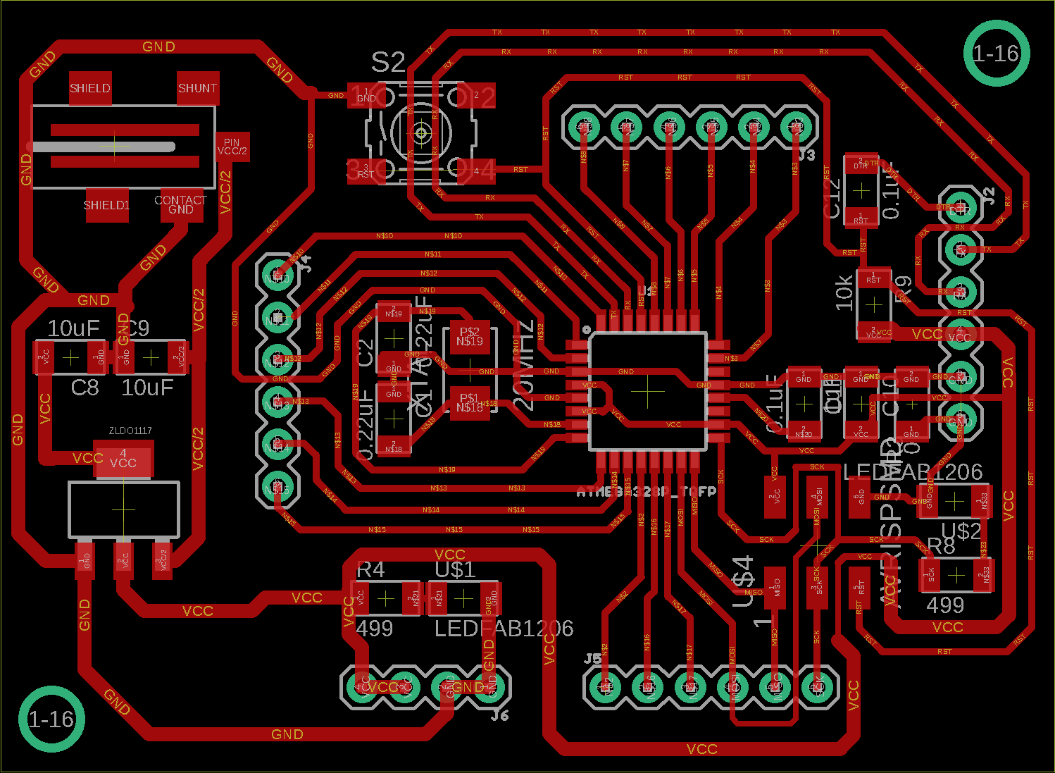
Initially, I wanted to build a general purpose PCB for trying different types of output devices during this week. Also it could be helpful to have this kind of PCB for future weeks. Here are some boards that I planned to replicate:
I spent some time trying to understand both designs and reading complementary articles about electronics. Since It was taking me more time than expected I decided to switch to a simpler board for this week, so I started working on the hello.servo board.
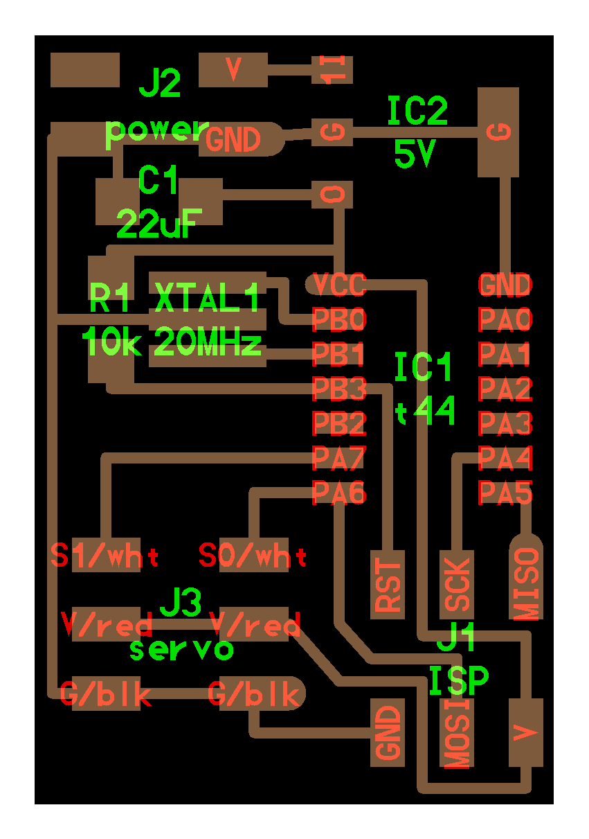
I almost replicated Neil’s design in Eagle, the only difference was the voltage regulator. I couldn’t find the same component in our inventory, but I found other two 5V voltage regulators instead:
- Linear Voltage Regulator IC Positive Fixed 1 Output 1A SOT-223 (NCP1117ST50T3GOSCT-ND)
- Linear Voltage Regulator IC Positive Fixed 1 Output 100mA SOT-23-3 (LM3480IM3-5.0/NOPBCT-ND)
The main difference is that the output current is 1A for the first Voltage regulator and 100mA for the second one. HobbyKing’s site didn’t show any information about the supported current for the servo that I had chosen, so I had to search that infomation in other forums. In one forum some users mentioned that this servo needs approximately 100mA when idle and higher values when it is working with loads. So I decided to go with the 1A Voltage regulator.
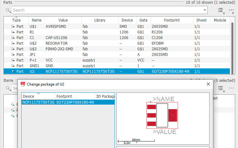
Pin configurations on voltage regulators varies very often so I downloaded the Eagle component for the same component we have in our fablab and used it in my design in order to avoid shorcircuits in my board.
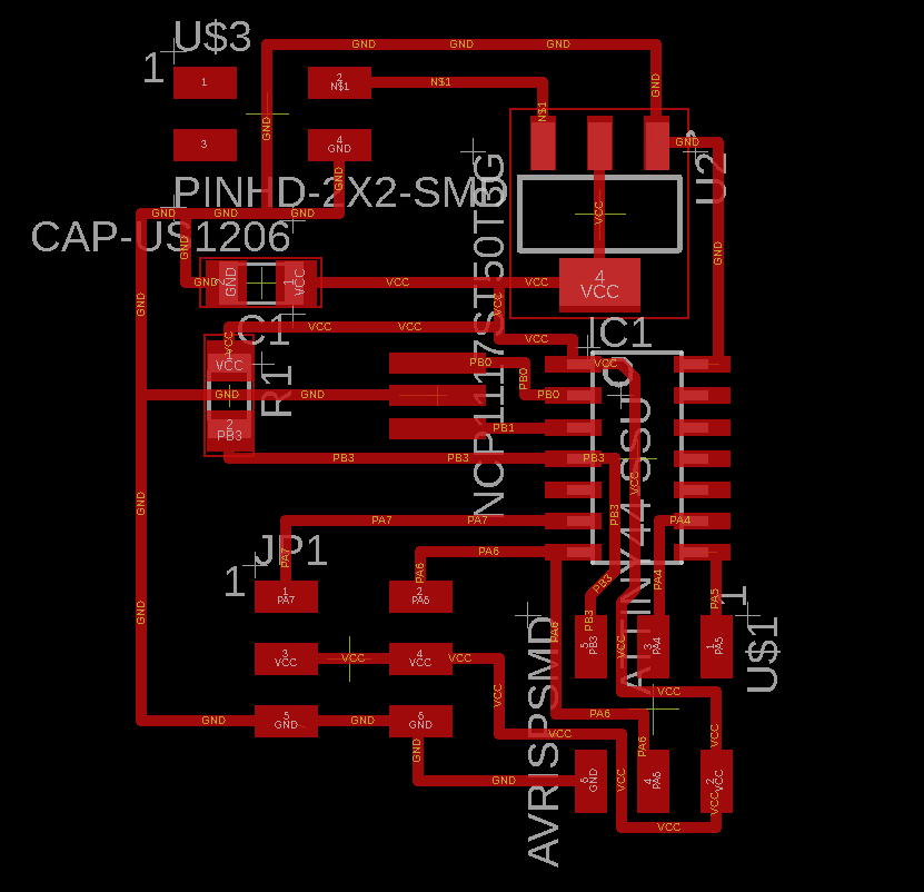
Then I exported the design to a gerber file, imported it into Flatcam and generated the nc jobs for the cutout (using a 1/32 inch endmill) and traces (using a 1/64 inch endmill). And then I proceeded to mill the board.
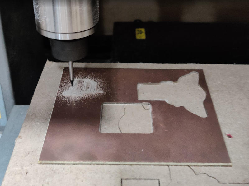
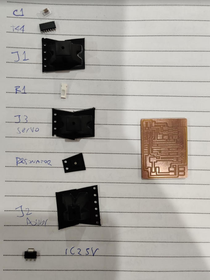
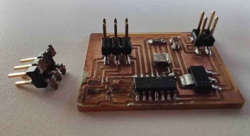
After milling the board, I cleaned it a bit and proceeded to solder the components.
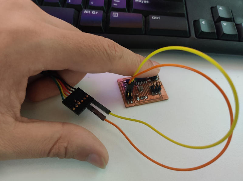
This board needs power to be able to be programmed. In order to do that, I connected a jumper wire from the power pin (RED) of the FTDI cable to the VCC input on my board and also connected another jumper wire from the ground pin (BLACK) to the ground input on the board.
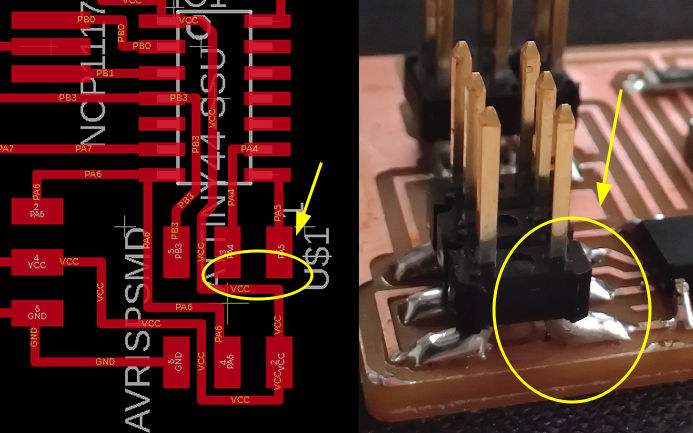
Then I tried to program the board, but I couldn’t… Apparently the board was not detected. After inspecting the board and performing a continuity test using a multimeter I noticed that due to an excess of solder I accidentally merged multiple traces in the j1 isp section.
I tried to fix that but accidentally I broke more traces  . So I had to use a piece of cable to reconnect the affected parts.
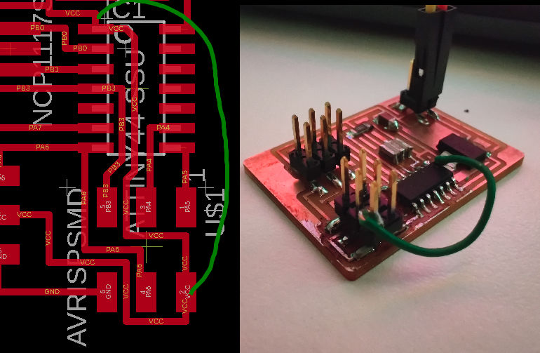
Finally, when I connected my board to the programmer and tried to load a simple program it worked! I’ll try to use bigger distances in traces in my following designs to avoid this kind of problems in the future.
Programming the board
First, I powered the board (using an external power supply) and connected the servo to the corresponding connectors. Then, I downloaded the hello.servo.44.c example code and the corresponding makefile and run the following command to program the board:
sudo make -f hello.servo.44.make program-usbtiny
Once the program was loaded into the board the servo started moving:
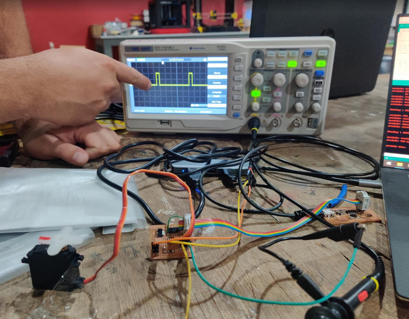
Finally, I used the oscilloscope to monitor the signals sent to the servos to control the movement. Every time I changed the pulse width in the code, the signal changed as well.
Sadly, I broke my board again so I couldn’t test other programs. Luckily I have an Arduino UNO and a Raspberry Pi Zero W so I proceeded to program them to use servo motors.
Arduino UNO board
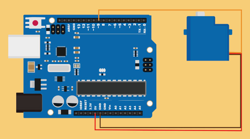
First I connected the servo to the 5V, GND and ~9 pins as shown below:
Then I created a new sketch in Arduino IDE and followed these steps:
- Include the
library, - Create a Servo instance called myServo
- Configure the servo instance to start using the pin 9
- Update the servo position.
//Servo Arduino 1

#include <Servo.h> // Step1

Servo myServo; // Step2

int servo_position = 0;

void setup() {

  myServo.attach (9); // Step3

}

void loop() {

  for (servo_position = 0; servo_position <=180; servo_position +=1){

    myServo.write(servo_position); // Step4
    delay(10);
  }

  for (servo_position=180; servo_position >= 0; servo_position -=1){

    myServo.write(servo_position);
    delay(10);
  }
}
This program basically moves the servo between position 0 and 180 as shown below:
Then I modified the program to make the servo do 5 “pushups” each side. I even made it shake for the first 5 pushups.
// Servo Arduino 2

#include <Servo.h>

Servo name_servo;

int servo_position = 0;
int reps = 0;
int totalReps = 5;
int shakes = 0;

void setup() {
  name_servo.attach (9);
}

void loop() {

  for (reps = 0; reps <totalReps ; reps +=1){
    for (servo_position = 20; servo_position <=90; servo_position +=1){
      name_servo.write(servo_position);
      delay(5);
    }
    for (shakes= 0; shakes<10; shakes+=1){
      for (servo_position = 90; servo_position >=80; servo_position -=1){
        name_servo.write(servo_position);
        delay(10);
      }
    }
    for (servo_position = 90; servo_position >=20; servo_position -=1){
      name_servo.write(servo_position);
      delay(5);
    }
    delay(100);
  }


  for (reps = 0; reps <totalReps ; reps +=1){
    for (servo_position = 110; servo_position <=180; servo_position +=1){
      name_servo.write(servo_position);
      delay(5);
    }
    delay(200);
    for (servo_position = 180; servo_position >=110; servo_position -=1){
      name_servo.write(servo_position);
      delay(5);
    }
    delay(100);
  }

}
Raspberry pi Zero W board
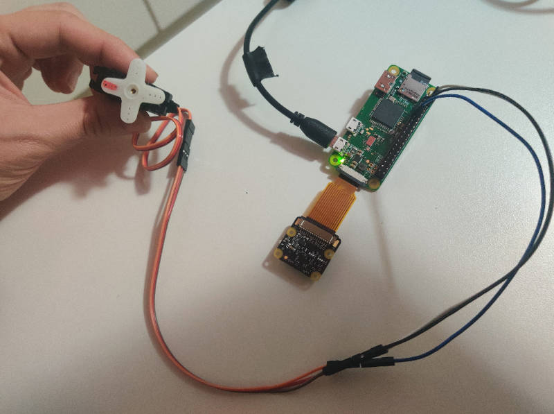
First I connected the servo to the corresponding GND, 5V and 11 Pins in the raspberry pi board. Then I connected the board to the power supply and waited for it to start.
I found a video made by Gary Explains that explains how to use servo motors with raspberry pi boards:
So I connected to my raspberrypi board and created the following python script:
# Servo Rpi 1

from gpiozero import Servo
from time import sleep

servo = Servo("BOARD11")

print("Start in the middle")
servo.mid()
sleep(5)
print("Go to min")
servo.min()
sleep(5)
print("Go to max")
servo.max()
sleep(5)
print("And back to middle")
servo.mid()
sleep(5)
servo.value = None;
It basically controls the servo using the pin 11 and moves it to the min (0), max(180) and middle positions(90). However, controlling the servo this way has some undesired effects:
It seems that the servo is having a hard time keeping the positions. This happens because the pulses are generated by software and if the software is out by even one millisecond then the motor thinks it needs to be somewhere else. Luckily the gpiozero library allows us to use different subsystems for controlling the pins… so we can use pigpio which is a special library that has hardware based timing for pwm and for servo pulses.
So… According to the gpiozero library, before creating the servo, we must create a factory and then assign that factory to the servo as shown below:
# Servo Rpi 2

from gpiozero import Servo
from time import sleep

from gpiozero.pins.pigpio import PiGPIOFactory

factory = PiGPIOFactory()

servo = Servo("BOARD11", min_pulse_width=0.5/1000, max_pulse_width=2.5/1000, pin_factory=factory)

print("Start in the middle")
servo.mid()
sleep(5)
print("Go to min")
servo.min()
sleep(5)
print("Go to max")
servo.max()
sleep(5)
print("And back to middle")
servo.mid()
sleep(5)
servo.value = None;
Also, before running the python script we need to make sure the pigpiod service is running on the raspberry pi. This can be done by running the following command in the raspberry pi board:
$ sudo pigpiod
Now the servo is controlled in a better way.
Final words about servos
During this week I learned about different types of motors. Initially I was interested in servos, because it looked useful for my final project. I also learned how to control servos using arduino boards, raspberry pi boards and even boards built by me. Although I succeeded in controlling this kind of motor accurately, their range of movement is usually very limited (around 180 degrees)… That’s the reason I’m considering using Stepper motors instead… since their range of movement is more suited for clock shaped devices. More information about how to use Stepper motors is available at my final project’s page).
RGB LED
During the Networking week I added a RGB LED to my bluetooth board. Since it is an output device I decided to add a section about it on this page. The board also contains components for the bluetooth module to work, but in this section I’ll highlight only the components related to the RGB LED. To see more about the fabrication steps and the bluetooth connections of this board please visit the Networking week’s page.
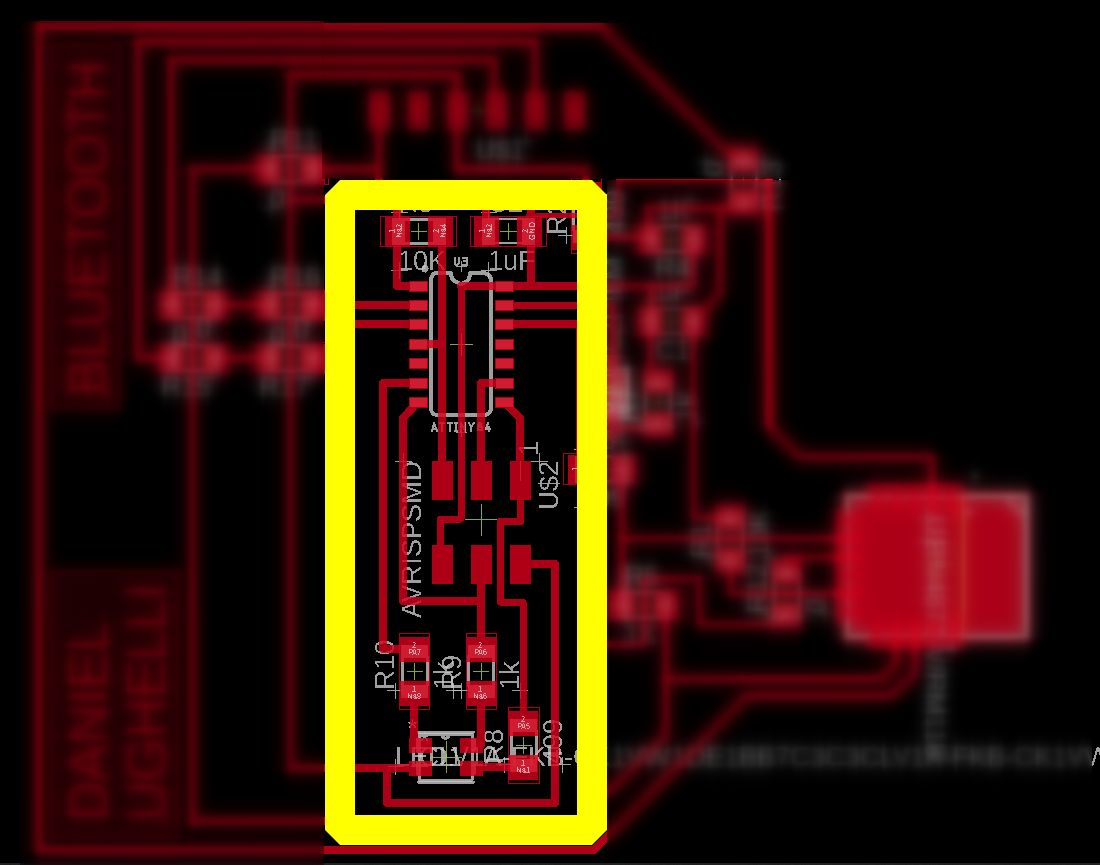
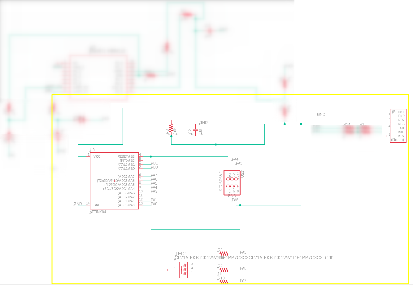
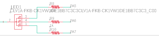
The RGB LED has the following pins:
- A common anode (Pin 2, in the schematic), which is connected to VCC.
- Red (Pin 1, in the schematic), which is connected to the pin PA7 of the microcontroller.
- Green (Pin 4, in the schematic), which is connected to the pin PA6 of the microcontroller.
- Blue (Pin 3, in the schematic), which is connected to the pin PA5 of the microcontroller.
In this way, we can send signals from 0 - 255 to each color pin in order to set its intensity. For example:
- If we send 0 to all the color pins, the RGB will be off.
- If we send 255 to the “Red” pin and 0 to the other pins, the RGB LED will shine RED.
- If we send 255 to the “Red” and “Green” pins, the RGB will shine YELLOW.
- Finally, If we send 255 to all the color pins, the RGB will become WHITE.
The code to send these signals to the RGB LED is shown below:
int red_light_pin= PA7;
int green_light_pin = PA6;
int blue_light_pin = PA5;
void setup() {
  pinMode(red_light_pin, OUTPUT);
  pinMode(green_light_pin, OUTPUT);
  pinMode(blue_light_pin, OUTPUT);
}
void loop() {
  RGB_color(255, 0, 0); // Red
  delay(1000);
  RGB_color(0, 255, 0); // Green
  delay(1000);
  RGB_color(0, 0, 255); // Blue
  delay(1000);
  RGB_color(255, 255, 125); // Raspberry
  delay(1000);
  RGB_color(0, 255, 255); // Cyan
  delay(1000);
  RGB_color(255, 0, 255); // Magenta
  delay(1000);
  RGB_color(255, 255, 0); // Yellow
  delay(1000);
  RGB_color(255, 255, 255); // White
  delay(1000);
}
void RGB_color(int red_light_value, int green_light_value, int blue_light_value)
 {
  analogWrite(red_light_pin, red_light_value);
  analogWrite(green_light_pin, green_light_value);
  analogWrite(blue_light_pin, blue_light_value);
}
And here are the final results:
Files
- Eagle project
- hello.servo.44.c
- hello.servo.44.make
- servo-arduino1.ino
- servo-arduino2.ino
- servo-rpi1.py
- servo-rpi2.py
- rgb-led.ino