4. Computer-Controlled Cutting
This week we learned about computer-controlled cutting using Laser and Vinyl cutting machines. This time we worked on group and individual projects to put into practice what we learned on the global lecture. In this article I’ll focus mainly on the individual assignment. To see more details on the group project, please visit this week’s article on our FabLab’s page.
The individual assignment of this week consists in:
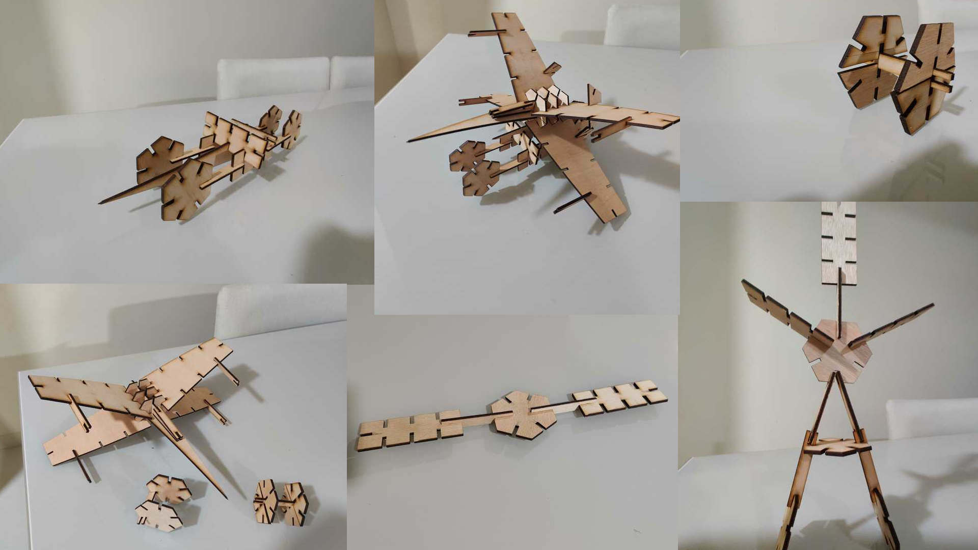
- Designing, laser-cutting, and documenting a parametric construction kit, accounting for the lasercutter kerf, which can be assembled in multiple ways,
- Cutting something on the vinylcutter.
Checklist:
- Link to the group assignment page.
- Explain how you parametrically designed your files.
- Document how you made your press-fit kit.
- Document how you made your vinyl cutting.
- Include your original design files.
- Include your hero shots.
Laser Cutting
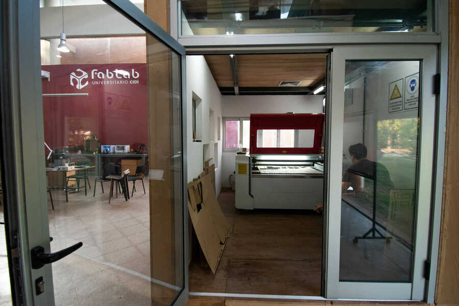
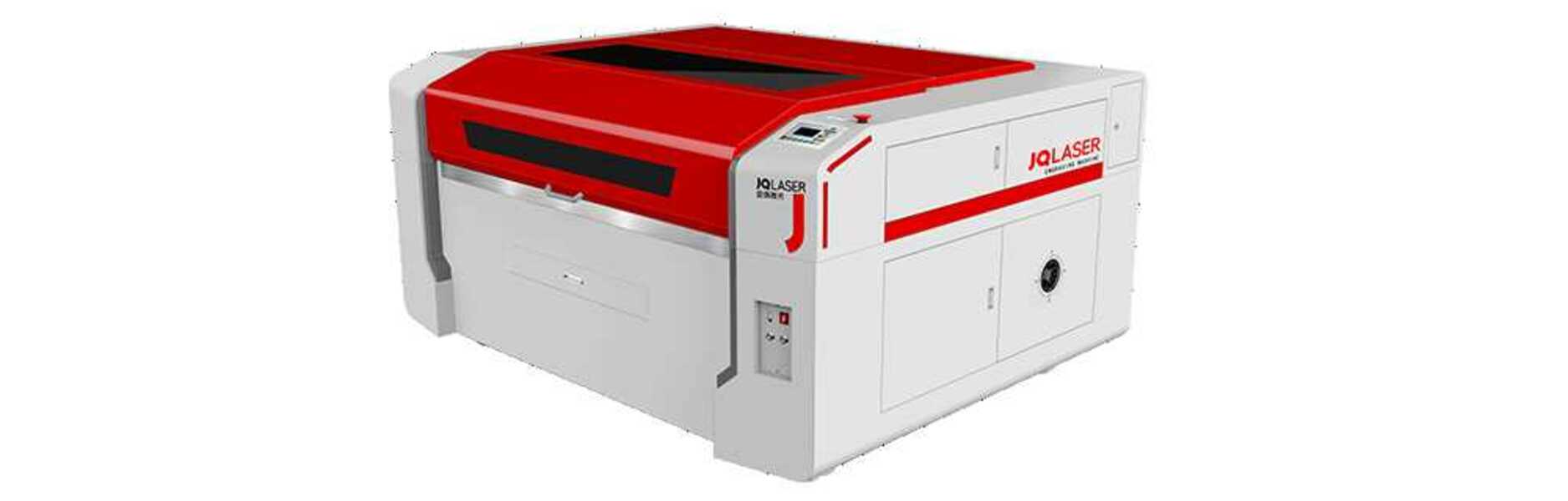
Our FabLab is equipped with a JQ Laser JQ-1390 Laser Cutting Machine, which is installed in an isolated room with dedicated ventilation and refrigeration systems.
- Laser type: Sealed CO2 laser tube
- Laser power: 80W Beijing Reci brand
- Maximum cutting area: 1300 x 900mm
Results from Group Assignment
In this section, I’ll show some results that we found during our group assignment. To see a detailed description about this please visit our fablab’s site.
The material that we had available for our assignments was a 3mm plywood sheet. In order to cleanly cut that material, there are some parameters and values that we had to set.
-
Laser power: Measured in percentage [0% - 100%]. Low values are used for materials such as paper; High values are used for more resistant materials.
-
Cutting Speed: Measured in mm/s. When using fast speeds the exposure times of the material to the laser is short; in the other hand, slow speeds lead to long exposure times.
After trying different combinations of values, we found that to cleanly cut a piece in a 3mm plywood the cutting speed should be 20mm/s using 40% of laser power.
Additionally, our designs should consider that every time a laser passes along the material it burns part of it. So, in order to cut accurate models the KERF value should be considered. During our groupal asssignment we found that the kerf value is 0.2mm.
Press-fit construction kit
Last week I decided to stick to Fusion 360 and learned some basics of parametric modeling, so I used it to design some basic components for my press-fit construction kit.
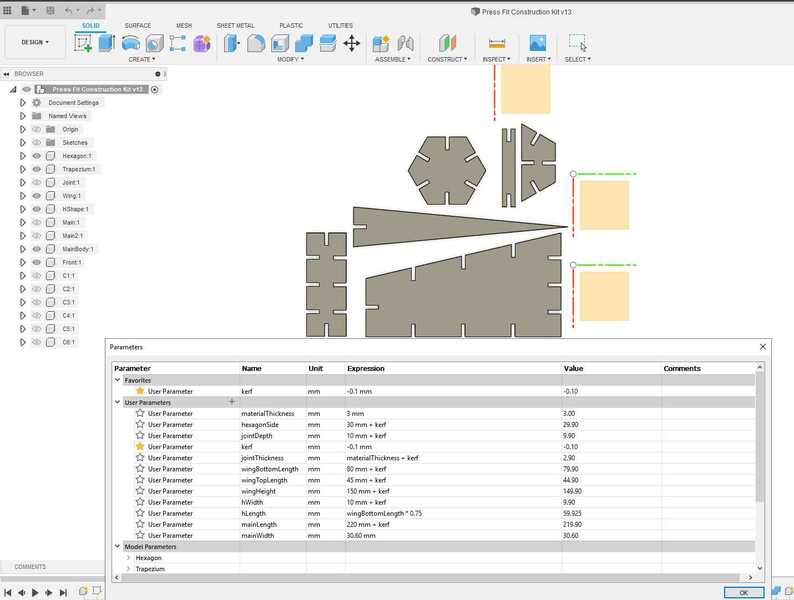
In order to do that, I selected modify > change parameters to start creating parameters such as Kerf, materialTickness, etc. Then I used those values when sketching my components, avoiding the use of “magic numbers” for dimensions.
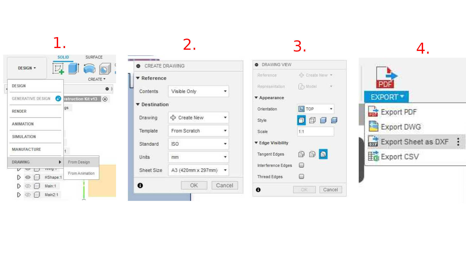
After designing the press-fit construction kit, I exported my design to a DXF file. Initially, I had a hard time exporting each components sketches to separated DXF files and merging them in a single file using Inkscape. Fortunately, Katrina showed me a simpler way to do it:
- Go to Design > Drawing > From Design;
- On the CREATE DRAWING modal, select
Contents: Visible OnlyandDrawing: Create New(A new document will be created). - On the DRAWING VIEW modal, select
Orientation: TopandScale: 1:1. Then, the figures should appear in the new document. - Finally, select
Export > Export Sheet as DXF.
Additionally, Silvia - our local instructor - helped me to rearrange my design using a technique called “Nesting” in order to make better use of our material.
Then I loaded the DXF into the Laser Cutting Software (PowerCut) and followed these final steps:
- Set the power/speed parameters;
- Selected the lines that should be cutted/engraved
- Send the file to the Laser Cutter.
- Set the origin on the canvas; fix the origin.
- Start the laser.
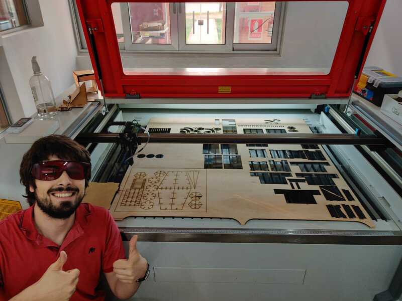
Finally, after the Laser Cutter machine stopped and the fumes produced during laser cutting dissapeared, I removed my models from the plywood sheet and started to assemble different things.
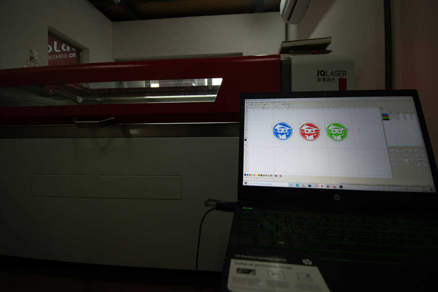
Vinyl Cutting
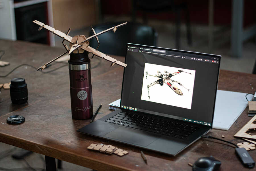
The Vinyl Cutter that we have in our lab is a GCC Puma IV 60 LX. I used Inkscape for preprocessing the images that I wanted to cut. I imported some raster images that I found on Internet and vectorized them.
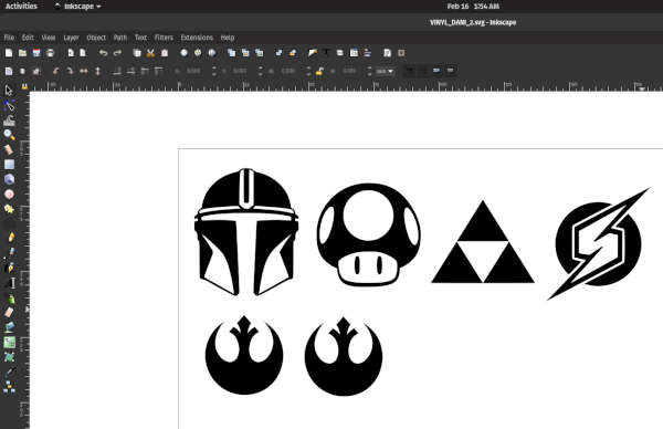
To vectorize these images, I select them and then went to Path > Trace Bitmap. Finally, I exported this design as a DXF file.
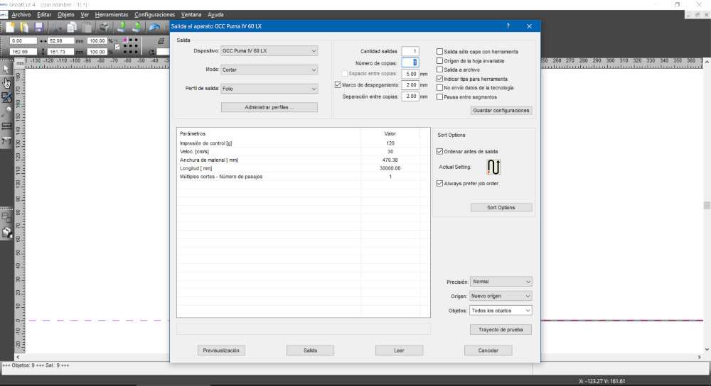
Then I imported the DXF File into the Vinyl Cutting Software (GreatCut 4) and set the following parameters:
- Speed: 30 cm/s
- Pressure: 120 g
- Material width: 470.38 mm
- Length: 30,000 mm
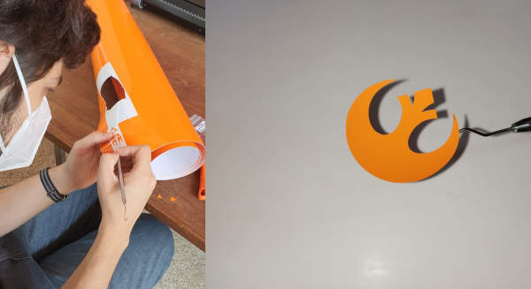
Finally, after the Vinyl Cutter stopped, I carefully removed the vinyl sticker using a exploratory probe: