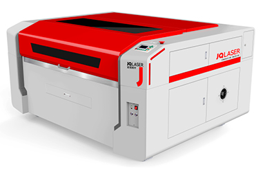
Laser cutting machine: Characterization
Machine factory specifications:
 |
|
|---|
Laser cutting machine. Using guidance
- Turn the room vent on
- Turn the AC on (17°C)
- Turn the “internal vent of the machine” on (be aware of the gray cable to be plugged in to the UPS)
- Turn the machine on (red button) and the laser button (green)
- Edit your file on the software “power cut”:
- Load your dxf file
- Set power and speed layer by layer (Remember! it depends on your material and thickness)
- Put layers in order, engraving first, cutting after to avoid pieces to fall apart before engraving
- Simulate the path of the laser
- upload your file to the machine
- Move the laser to an effective origin (be aware of the available material area and always think about minimize the waste)
- Set the origin
- Mark the origin with a tiny laser shot
- Simulate the laser moving within the cutting area
- Open the lid
- verify the Z using the white little plastic block
- Close the lid
- press play
- DON’T LEAVE THE MACHINE UNATTENDED
Laser cutting machine. power, speed, kerf, press fit
Material and thickness: 3mm Plywood
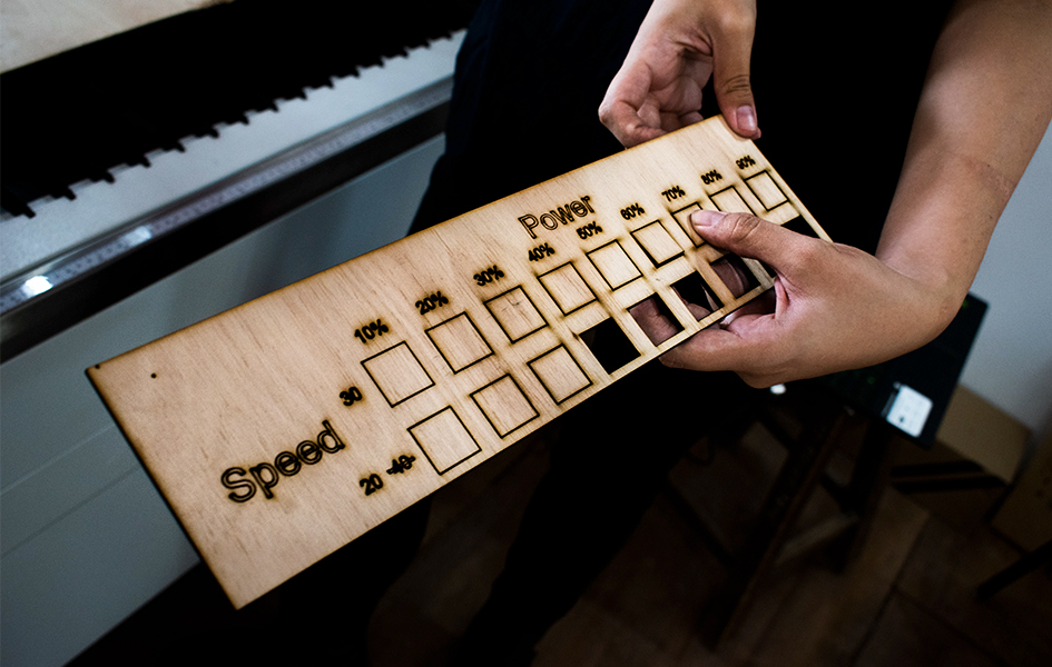
Determining power and speed
By doing this test we want to know which speed and power do we need to cleanly cut a 3mm plywood piece using our machine.
Remember, this always will depend on: the machine, the material and the thickness. Every time you change one of these variables, you need to do this test.
How did we do it?
- Design a simple file containing little shapes in a “table” with columns of speed and rows of power
- Load the file to “power cut” software and apply different colors to each shape so we can have different “layers”
- Assign power and speed to each “layer” following the indications in the coincident row and column (speed and power) Also select “cut” or “engrave” in the specifications, All these will be “cut” even though we have labels to engrave. It is so because, in this case, we don’t have shapes to “fill in” or “paint” we just want them to be visible marked on the plywood. Use engrave only when you intentionally want to “draw/paint” something. To “visible mark” your labels on the material use “cut” with 10 power, 80 speed.
- Put layers in order depending on having or not labels to engrave. The last thing to cut here will be an external square to separate the piece of the original material.
- Simulate the path of the laser in the software
- Upload the file into the machine and start!
Results: To cleanly cut a piece in a 3mm plywood speed is 20 and power is 40
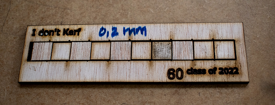
Determining KERF
Every time a laser passes along a given material it “burns” part of it. We need to take this into consideration when designing anything we want to cut because if we, let’s say, want a piece with 5mmx5mm area, if we draw as it is at the end we’ll have a smaller piece than we wanted. The amount of material the machine will burn for a 3mm plywood is the purpose of this test. Once again, do this every time you need to change your machine, material or thickness
How did we do it?
- Design a simple file with 10 squares with 10mm each placed in a row forming a shape like this (add photo)
- Assign a color for the vertical lines inside the rectangle and another one to the outside rectangle, and the last one will be for the boundary of the entire piece (so we can extract our work from the rest of the plywood)
- Load the file to power cut and apply 20 speed and 40 of power to all layers
- Put the vertical lines layer first, and the rectangle containing them after and the boundary rectangle last
- Start cutting
- Remove the material from the machine, also the little squares fallen
- Place all the squares inside the empty rectangle
- Measure the little empty part inside the rectangle using a calibrator
- Divide this by 11
- You’ll have your KERF!!
Warnings!
- Ensure your file has not overlapping lines before sending it to power cut software
- The machine just “reads” vectors
- All “text” should be converted to “curves”
Results: The calibrator showed 2,2mm. Dividing by 11 the result was: 0,2. KERF=0.2 for a 3mm plywood
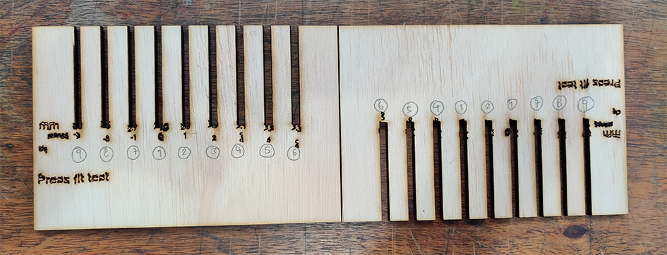
Press fit test
We do this to know the “clearance” of a given material when pieces of it join each other. The level of strength or smoothness between each piece will depend on the function they’ll have on our design (for instance, it could be a strong structural fit or a loose one to have a hinge). We call this “clearance” and it also varies with the machine, thickness and material. So do this test every time you change any of them.
How did we do it?
- Design 1 simple shape like this below we call it a “hair comb”
- Each empty long rectangle needs to have a different width starting with 0 in the center.
- Then add 0.1 mm each to the right and subtract 0.1 each to the left. 3 to the left and 5 to the right would be enough
- Add labels showing the width of each empty rectangle in mm and also name each with a number
- Copy and paste the shape so you have 2 identical
- Cut
- try combining each number among themselves and feel how easy or difficult it is to join them. Write your results in a table like this
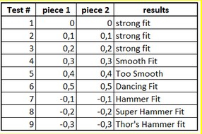
Results: