13. Networking and Communications
This week we learned about different ways to communicate between devices, including:
- Wired communication: Asynchronous, SPI, I2C
- Wireless communication: Bluetooth, WiFi.
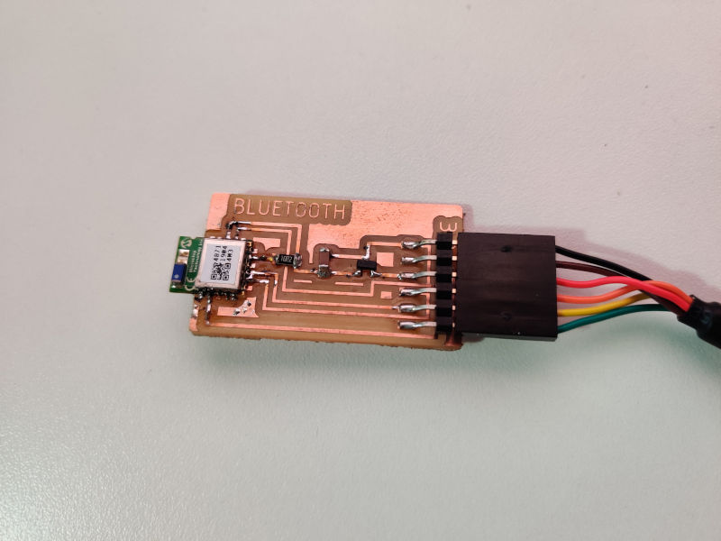
Bluetooth board
I decided to experiment with the Bluetooth module I found in our lab during this week, so I started with the examples Neil showed us on the global lecture.
Design considerations:
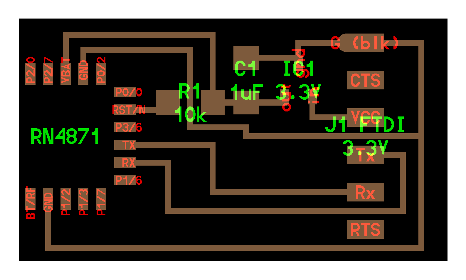
- I noticed that the example for RN4871 doesn’t have a microcontroller on it, so I decided to modify the board to add an attiny44 microcontroller and a RGB led to control over bluetooth.
- Also, the example board uses an 3.3V FTDI Cable, unlike the other boards I made in previous weeks. I decided to add voltage dividers in order to keep using a 5V FTDI cable to power the microcontroller and to power the bluetooth module using 3.3V at the same time.
- I also decided to connect the Bluetooth module’s TX/RX pins to the microcontroller to transmit/receive data from there.
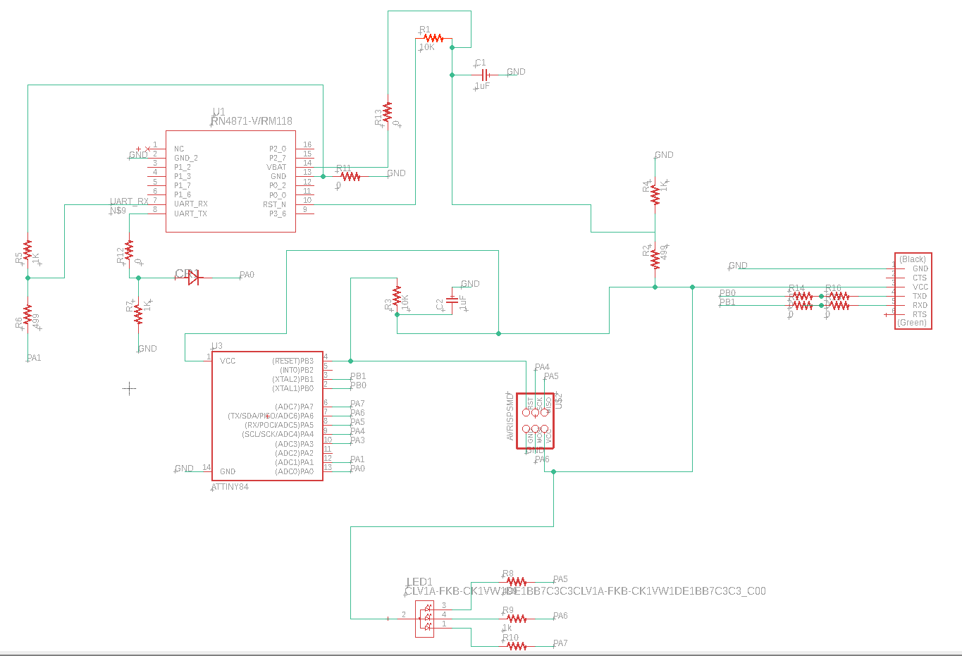
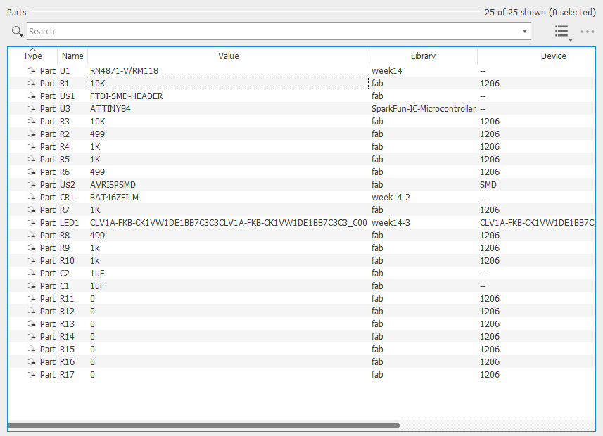
Unfortunately, I had to use 7 0Ohm resistors to join incomunicated board sections. There’s probably a better way to do it but for time’s sake I decided to use those resistors.
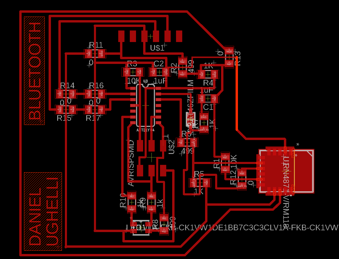
Fabrication
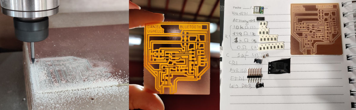
Then I proceeded to mill the board and solder the components. The bluetooth module seemed tricky to solder because of its size, but I soldered it relatively quickly.
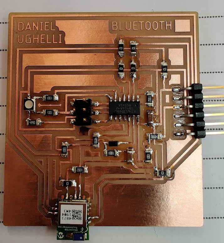
Testing the board
After soldering all the components, I proceeded to connect the board to the 5V FTDI cable and to my programmer and loaded teh following code to control the Rgb Led:
int red_light_pin= PA7;
int green_light_pin = PA6;
int blue_light_pin = PA5;
void setup() {
  pinMode(red_light_pin, OUTPUT);
  pinMode(green_light_pin, OUTPUT);
  pinMode(blue_light_pin, OUTPUT);
}
void loop() {
  RGB_color(255, 0, 0); // Red
  delay(1000);
  RGB_color(0, 255, 0); // Green
  delay(1000);
  RGB_color(0, 0, 255); // Blue
  delay(1000);
  RGB_color(255, 255, 125); // Raspberry
  delay(1000);
  RGB_color(0, 255, 255); // Cyan
  delay(1000);
  RGB_color(255, 0, 255); // Magenta
  delay(1000);
  RGB_color(255, 255, 0); // Yellow
  delay(1000);
  RGB_color(255, 255, 255); // White
  delay(1000);
}
void RGB_color(int red_light_value, int green_light_value, int blue_light_value)
 {
  analogWrite(red_light_pin, red_light_value);
  analogWrite(green_light_pin, green_light_value);
  analogWrite(blue_light_pin, blue_light_value);
}
Then, I tried to pair the bluetooth module with my smartphone but I couldn’t find it. Then I reviewed Neil’s video and noticed that I needed to send the following commands to the Bluetooth Module to configure it:
ECHO ON
SS,C0
R,1
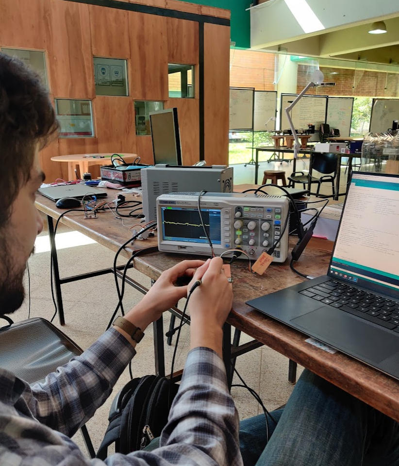
I tried to do that by using the SoftwareSerial library on my code but I didn’t managed to make it work. I used 2 softwareserial instances… one for the FTDI connector and another one for bluetooth. It turns out that only one instance can listen to events at the same time. You need to call the .listen() method explicitly to receive data from a specific instance. Although I managed to make the serial comunication through FTDI work, the bluetooth never responded my messages. I even monitored the bluetooth connections using the oscilloscope, but it seemed that no signals were emitted from the blutooth module.
Since I spent too much time with no results I decided to build a simpler board, so I used Neil’s example.
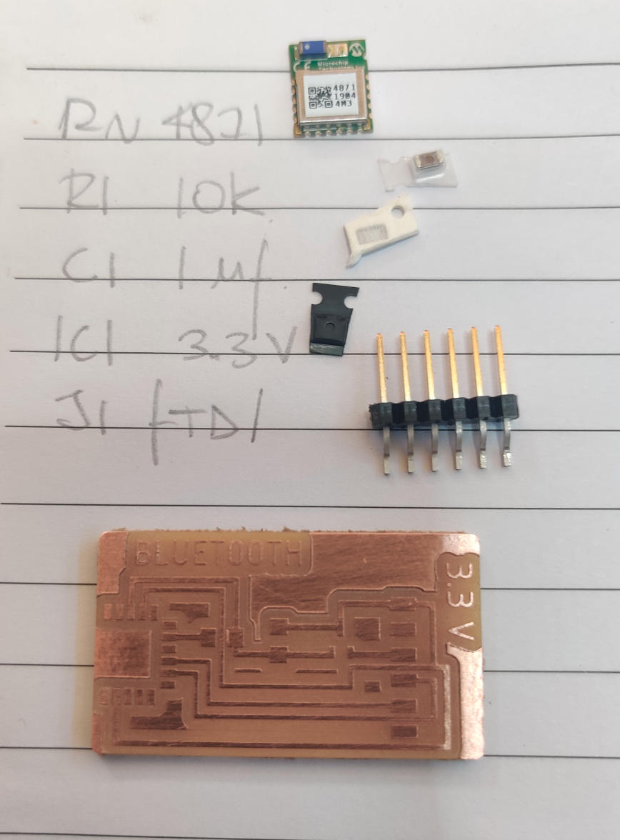
After soldering all the components I connected the board to my computer using the 3.3V FTDI cable. My smartphone detected a new bluetooth device almost immediately. This time I succeeded in configuring and comunicating with the bluetooth module. I used miniterm to connect to the board from my terminal: python3 -m serial.tools.miniterm -e /dev/ttyUSB0 115200. I also used a program called scrcpy to cast my smartphone screen to my laptop. The following video shows the steps I followed to communicate with the bluetooth board: