5. Electronics Production
During this week we learned how to operate a milling machine to produce PCB boards and solder SMD components on them. First, we had to characterize the design rules for out in-house PCB production process as a group assignment (more details on our group assignment’s page). Then, the individual assignment consisted in making an in-circuit programmer that includes a microcontroller.
Checklist:
- Link to the group assignment page.
- Document how you made the board.
- Document that your board is functional.
- Explain any problems and how you fixed them.
- Include a ‘hero shot’ fo your board.
Using FlatCAM
Abdón - our local instructor - recorded a series of videos (in spanish) on how to use Flatcam. These videos are available on his Youtube channel:
- How to download and install FlatCAM
- How to import files on FlatCAM
- How to generate nc files on FlatCAM
We used the following PNG file for characterizing the design rules of PCB production:
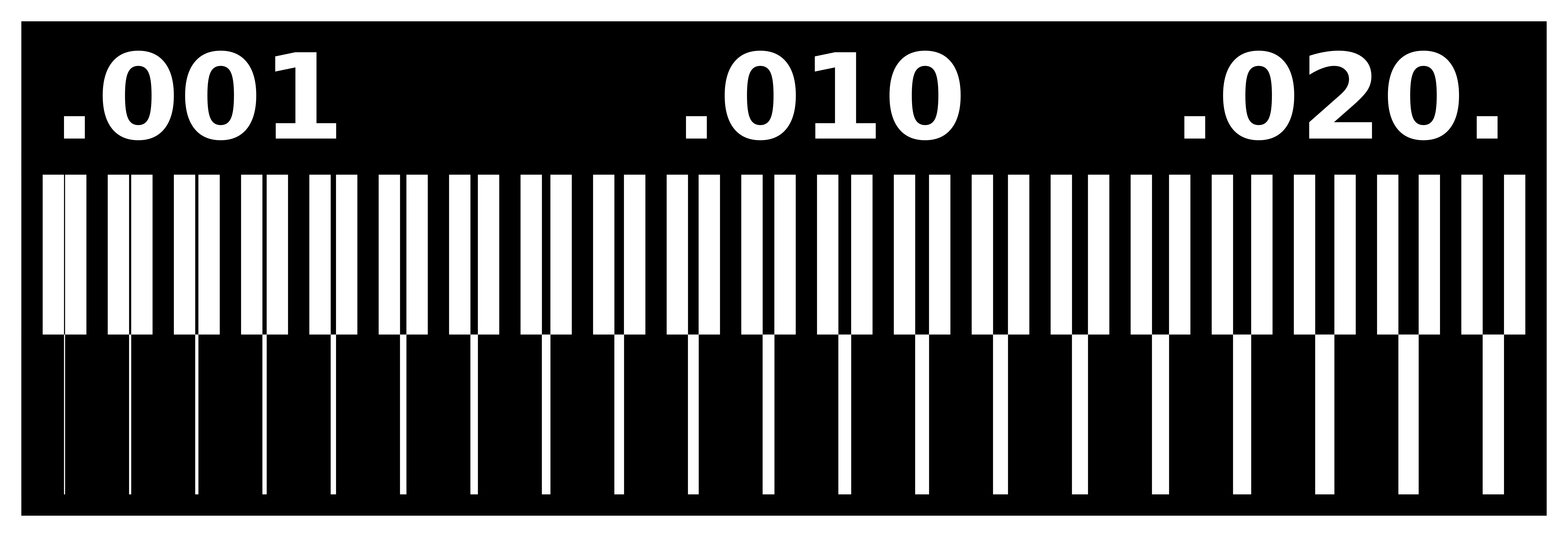
The milling machine needs a set of intructions to follow for cutting this design. We used FlatCAM to load this design, set some parameters and generate the .nc files for milling the traces and cutouts. Some things to take into account:
- Dark traces usually represent copper and the light traces represent the absence of it, so we had to invert the image before importing using GIMP (It is also possible to invert the image in FlatCAM using the invert tool)
- The tool type used in our tests is
C1. - The tool diameters should be expressed in decimals so:
1/32 inch = 0.79375 mmand1/64 inch = 0.396875 mm - Do not forget to set the spindle speed otherwise it won’t start rotating.
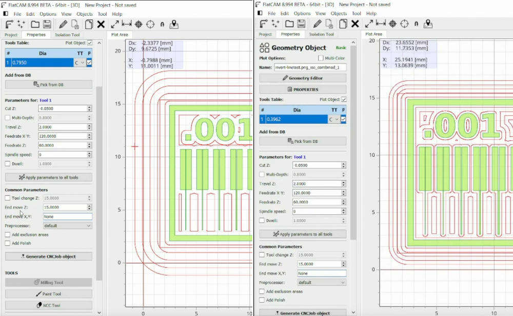
We generated .nc files for traces using 1/32 and 1/64 end mills in order to compare results.
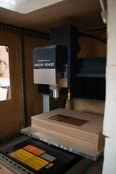
Equipment usage
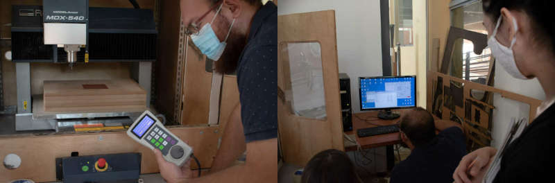
The equipment used for milling PCB boards on our lab is the Roland MODELA PRO II MDX-540 Milling Machine, which is installed in another isolated room alongside other noisy machines.
- Cuttable material: Plastic resin and light metal
- XYZ-axis travels: X x Y x Z: 500 x 400 x 155 mm
- Distance from spindle nose to table: Maximum 254 mm
- Table size: Width x depth: 550 x 420 mm
- Loadable workpiece weight: At acceleration of 0.2 G: maximum 12 kg, 0.1 G: 20 kg, 0.05 G: 20 kg
- XYZ-axis drive system: AC servo motor, 60 W
- Operating speed: Maximum 7.5 m/min
- Acceleration: 0.2 G, 0.1 G, 0.05 G
- Spindle motor: DC brushless motor, maximum 400 W
- Spindle speed: 400 to 12,000 rpm; 400 to 3,000 rpm for positioning and centering
- Tool chuck Collet method, maximum diameter of the tool: 10 mm
- Control command sets: RML-1 and NC codes
- Dimensions Width x depth x height: 745 x 955 x 858 mm
- Weight: 102 kg
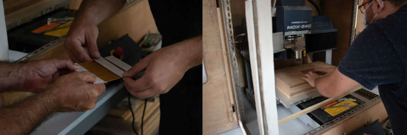
We used a 0.3 mm copper plate for our PCB board. In order to prevent movement when the machine is running, we put and removed some double sided tape on the bottom face of the plate before placing it on the sacrificial layer of the milling machine.
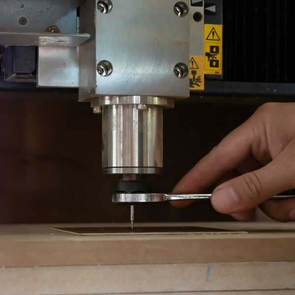
Then we followed these steps to install tools (1/32 and 1/64 end mills) on the milling machine:
- Open the spindle cover
- Fit the collet into the nut.
- Lightly tighten the nut and insert the tool.
- Support the tool with your fingers to keep it from falling as you tighten the nut (using a 24mm wrench on the top and a nut wrench on the bottom).
Then we set the coordinates of the origin on the plate using the handy panel:
- Press the COORD. SYSTEM key.
- Select the axis you want to move (X, Y, Z)
- Turn the hand wheel to start moving the tool on the selected axis.
- Hold down the ORIGIN key until an audible beep is sounded.
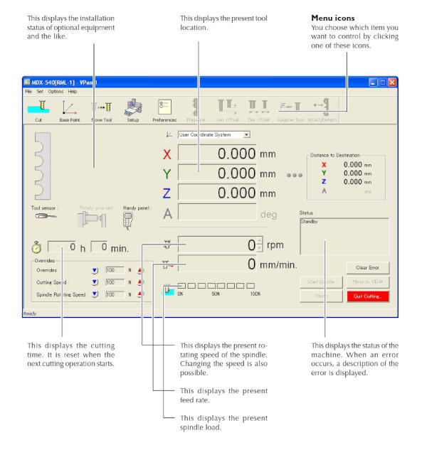
There is a computer next to the milling machine which has a dedicated program for controlling it. In order to do that, we openned VPanel, loaded our nc files and started the process:
For our tests, we cutted our internal traces using 1/32 and 1/64 mills. However we used the 1/32 end mill for the cutout in both cases.
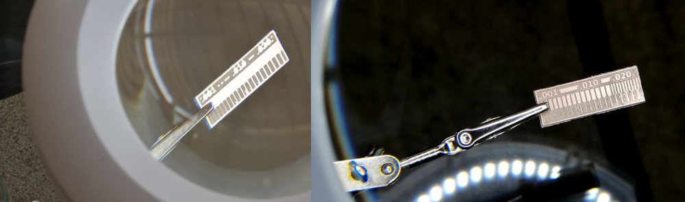
The above image shows the difference in milling resolution of 1/32 and 1/64 end mills. 1/64 end mill is better for milling traces and the 1/32 for cutting and drilling.
In-circuit Programmer
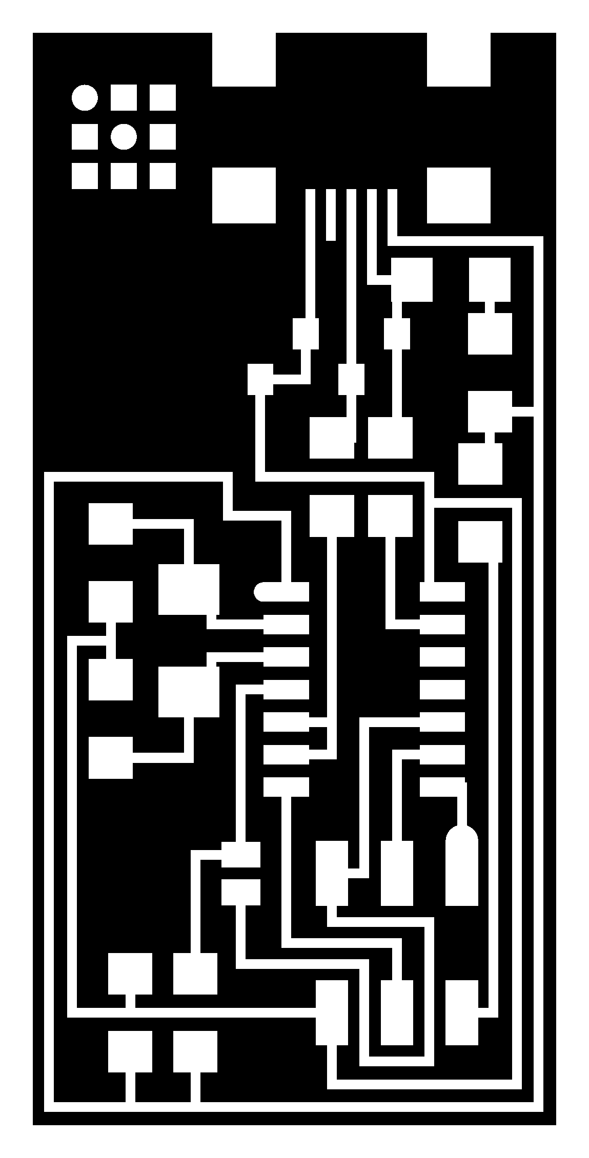
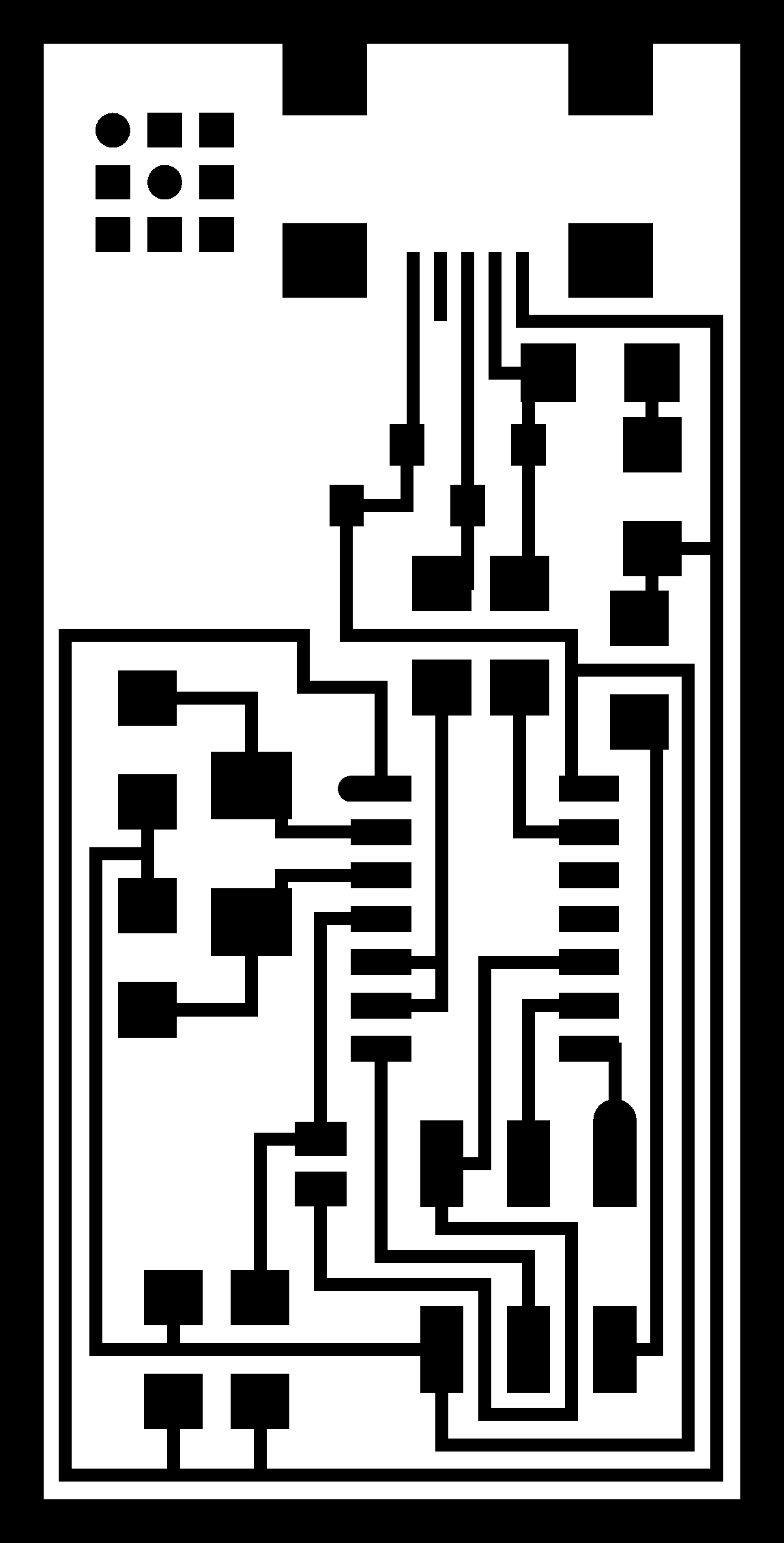
For our individual assignment, we had to make an in-circuit programmer that includes a microcontroller. Considering the components available in our lab, our instructors told us to work on ISP (original AVR) boards. So we ended up using the ISP designs available on the assignment page:

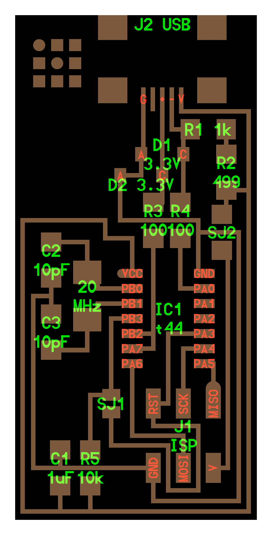
I loaded this design on FlatCAM, set the parameters we found on our group assignment and generated the .nc files for internal traces and cutout. Actually, I almost forgot to invert the image before importing it on FlatCAM (First mistake)… Fortunately Katrina noticed that and told me to fix that. Then I installed the 1/64 inch end mill on the Milling Machine, loaded the .nc file for internal traces in VPanel and started the process:
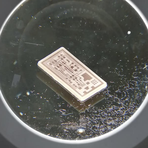
Then I removed the 1/64 end mill, installed the 1/32 end mill, loaded the cutout .nc file and started the cutting process. However, at some point during the cutting process the machine ignored the instructions on the .nc file and started to move all the axes in unexpected ways. Silvia and Abdón - our local instructors - reviewed my .nc code and there were no errors on it. Then, after trying different things we realized that the milling machine couldn’t cut the plate correctly because the 1/32 mill was inserted too deeply into the spindle so the spindle have to go beyond its limits to actually cut the plate (Second mistake). After adjusting the 1/32 end mill the board cutting process finished successfully and I removed the PCB from the plate and cleaned it a bit.
I followed these steps to clean the PCB:
- Remove the excess of copper using a a exploratory probe.
- Apply some Contact Cleaner and wait for it to dry.
- Clean the copper with steel wool until it’s bright.
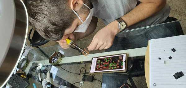
Having cleaned the PCB, I applied some flux on it and started to solder the SMD components following the designs.
During the process of soldering my components I made the following mistakes:
- Lost a small resistor. It probably went off the table or have blowed away.
- I accidentaly tore a copper trace from my PCB board when using the solder sucker. Fortunately Edgar helped me to replace the missing trace with solder and copper.
- After soldering the J2 USB component legs I realized that the internal pins were misaligned, so… when I tried to desolder this component another copper trace were torn from my PCB board.
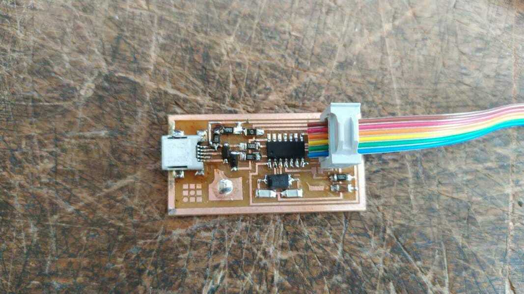
Finally, after soldering all the components shown in the designs we connected the board to an Atmel ICE and a two lights turned on.
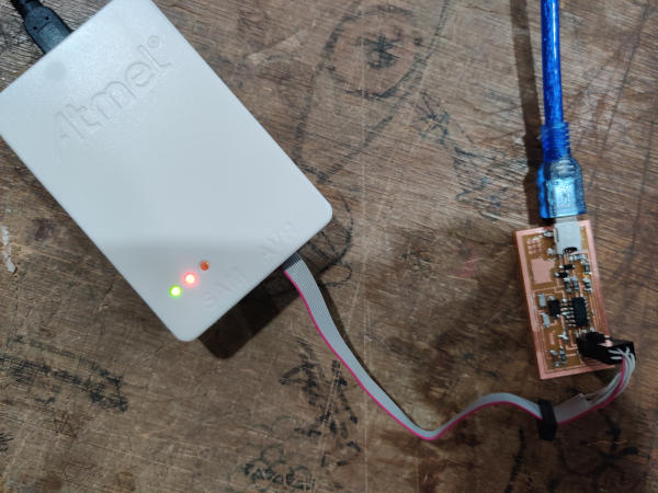
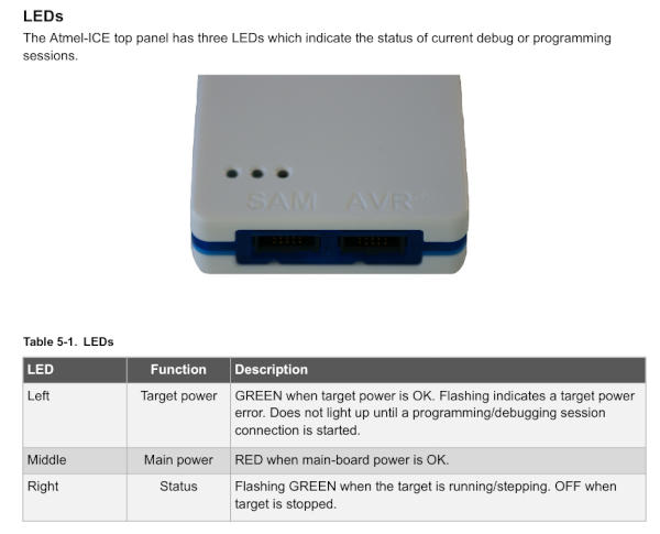
According to the ATMEL-ice user manual, the lights that turned on (left/middle) indicate that both the target and main board power is OK.
Programming the board
I used my linux partition to test the board and program it. In order to do that, first I run the following commands to setup my local environment:
sudo apt-get install flex byacc bison gcc libusb-dev avrdude
sudo apt-get install gcc-avr
sudo apt-get install avr-libc
sudo apt-get install libc6-dev
Then I downloaded the FabISP firmware and extracted it in my assignment’s folder. Then I opened the Makefile file and modified the following line:
AVRDUDE = avrdude -c atmelice_isp -P usb -p $(DEVICE) # edit this line for your programmer
Then I opened this folder in my terminal and ran the commands shown below to program the board:
make clean
make hex
make fuse
make program
All the commands shown above executed succesfully. So theoretically, the programmer should work. However, when I ran lsusb the board was not listed.
After adjusting some resistors and connectors without favorable results, Abdón recommended I mill a new board and stuff new components on it. So after redoing the board and running the programming process described above, the board was finally listed when running lsusb