Computer-Controlled Machine: Characterization
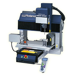
Machine factory specifications:
 |
|
|---|
Process
Software:Flatcam
One of our local instructors(Abdón Troche) recorded a series of videos(in spanish) on how to use FlatCAM. These videos are available on his Youtube channel:
- How to download and install FlatCAM
- How to import files on FlatCAM
- How to generate nc files on FlatCAM
We used the following PNG file for characterizing the design rules of PCB production:
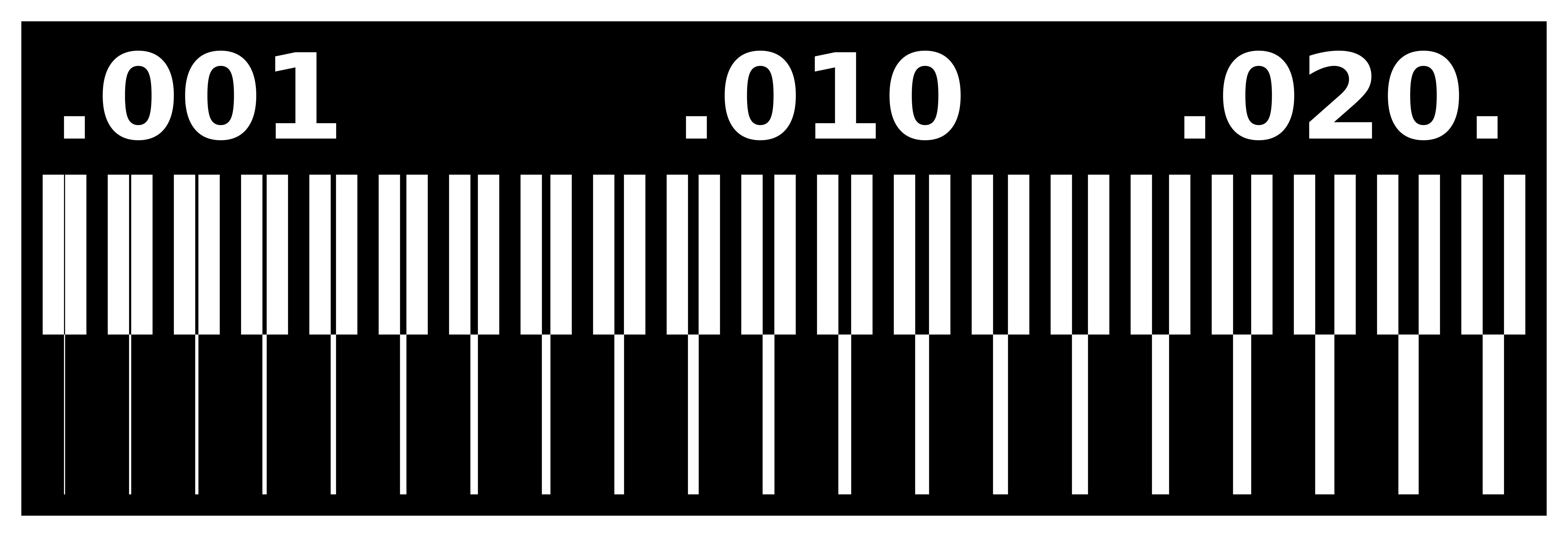
The milling machine needs a set of intructions to follow for cutting this design. We used FlatCAM to load this design, set some parameters and generate the .nc files for milling the traces and cutouts. Some things to take into account:
- Dark traces usually represent copper and the light traces represent the absence of it, so we had to invert the image before importing using GIMP (It is also possible to invert the image in FlatCAM using the invert tool)
- The tool type used in our tests is C1.
- The tool diameters should be expressed in decimals so: 1/32 inch = 0.79375 mm and 1/64 inch = 0.396875 mm
- Do not forget to set the spindle speed otherwise it won’t start rotating.
We generated .nc files for traces using 1/32 and 1/64 end mills in order to compare results.
Set up
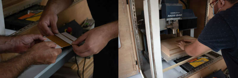
We used a 0.3 mm copper plate for our PCB board. In order to prevent movement when the machine is running, we put and removed some double sided tape on the bottom face of the plate before placing it on the sacrificial layer of the milling machine.
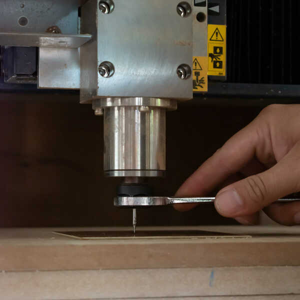
Then we followed these steps to install tools (1/32 and 1/64 end mills) on the milling machine:
- Open the spindle cover
- Fit the collet into the nut.
- Lightly tighten the nut and insert the tool.
- Support the tool with your fingers to keep it from falling as you tighten the nut (using a 24mm wrench on the top and a nut wrench on the bottom).
Then we set the coordinates of the origin on the plate using the handy panel:
- Press the COORD. SYSTEM key.
- Select the axis you want to move (X, Y, Z)
- Turn the hand wheel to start moving the tool on the selected axis.
- Hold down the ORIGIN key until an audible beep is sounded.
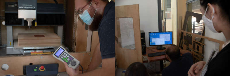
There is a computer next to the milling machine which has a dedicated program for controlling it. In order to do that, we openned VPanel, loaded our nc files and started the process:
Results
For our tests, we cutted our internal traces using 1/32 and 1/64 mills. However we used the 1/32 end mill for the cutout in both cases.
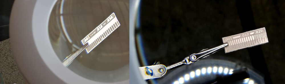
The above image shows the difference in milling resolution of 1/32 and 1/64 end mills. 1/64 end mill is better for milling traces and the 1/32 for cutting and drilling.
