8. Computer-controlled machining
Checklist:
- Link to the group assignment page
- Document how you designed your object (something BIG)
- Document how you made your CAM-toolpath
- Document how you made something BIG (setting up the machine, using fixings, testing joints, adjusting feeds and speeds, depth of cut, etc)
- Describe problems and how you fixed them.
- Include your design files and ‘hero shot’ photos of final object.
Equipment
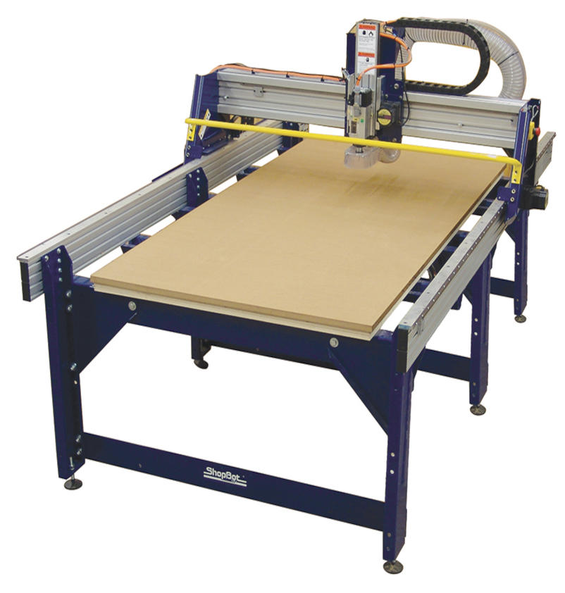
Our fablab is equiped with a Shopbot PRSalpha which is installed alongside the Roland MODELA PRO II MDX-540 milling machine used for milling our PCBs in previous weeks. Both machines are noisy, so they are installed in a isolated room. However, the Shopbot is way bigger - and noisier - than the Roland MODELA PRO II, it occupies almost the entire room. Due to its size, this machine is more suitable for fabricating really BIG things.
Safety recommendations
Ok, It’s time to get serious. I don’t want to frighten you, but we are dealing with a ~4 horsepower motor, it cannot tell the difference between wood and human body parts… It can hurt you… and it can hurt you quick. This machine is sharp, powerful and fast. So here are some safety considerations to take into account:

-
Preparation:
-
Wear safety glasses.
- Spindle is less noisy than regular router motors but pick up some hearing protection if you are cutting for a long period of time.
- Tuck in any loose clothing you have on (jewelry, hoodie strings)
- Long hair has to be tied back

Wearing safety equipment
-
When using the machine:
-
Be mentally focussed.
- You need to know where the Emergency shutoff switch is.
- Know your tool path before you start the machine.
- Know how to load and unload cutting tools.
- Stay away from the work area until the router bit comes to a complete stop. You cannot anticipate where it’s going to move.
- Make sure someone can watch the machine until the project finishes.
On this latter point, remaining with your CNC is the safest way to use it. But, if you have to leave the room for a moment:
- Place a camera pointing the cnc router. Activate sounds to identify problems immediately.
- Install remote control programs to stop the cnc job faster.
- Install smoke detectors.
Usage
In order to start using this machine you should follow these steps:
- Place your material on top of the sacrificial booard. It should be aligned with the machine origin.
- Make sure material is properly clamped.
- Turn on the compressor.
- Install the tool/endmill you want to use.
- Go to the computer used to control the machine and start Shopbot3.
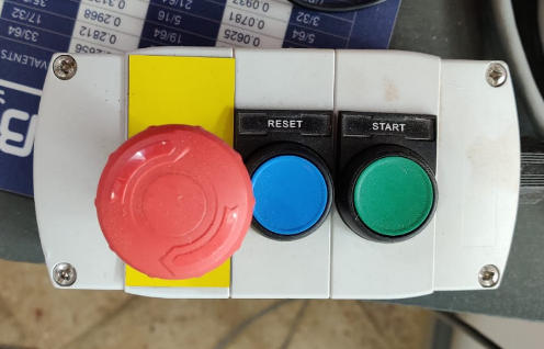
- Press the reset physical button (blue). You should hear a sound after that.
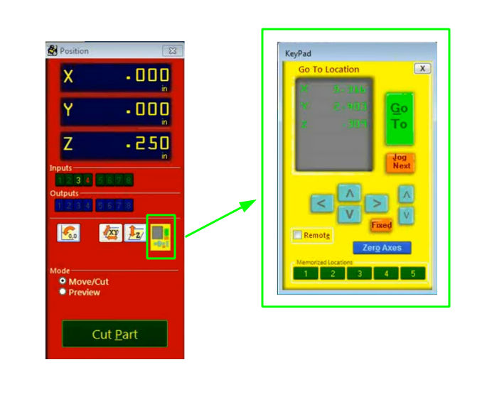
- Set origins using shopbot controls. X,Y can be moved using the arrows in the keypad (yellow window). To set origin press the Zero axes button and seled X and Y.
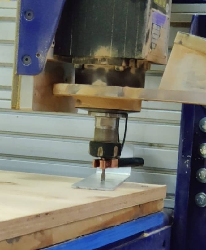
- Set Z axis using the auxiliary aluminum plate. In order to do that press the Z axis button in the Position window (red window).
- To start cutting press the Cut Part button in the red window and select a valid gcode file.
- Press Start button (Green) to start the drill and then press enter in the keyboard.
- Once the machine stops, remove the pieces using gloves.
- Clean the working area using a vaccum cleaner.
Group Assignment
Feeds vs Speeds
-
Feedrate: The distance the spindle moves relative to the time it takes to move along the workpiece. Units are distance / time, usually in/min or mm/min.
-
Spindle Speed: The rotational speed of the spindle. Units are revolutions per minute or RPM.
On one hand, if the feedrate is fast and the spindle speed is too slow, the end mill will break under the lateral pressure.
On the other hand, if the feedrate is slow and the spindle speed is faster than it needs to be, there will be little risk of breaking the end mill, but the job will take longer than it needs to
Direction
It refers to the direction of the spindle’s travel in relation to the rotation of the end mill. Spindle rotates clockwise.
-
Conventional milling: End mill contacts the stock on the left side of the tool. This means that the chip size effectively starts at zero and increases towards the end of the rotation. This generally yields the best results in terms of finish quality and accuracy.
-
Climb milling: End mill contacts the stock on the opposite side, meaning the chip size starts at the maximum and tapers to zero at the end of the rotation. This puts more strain on the tool and can decrease accuracy if the stock deflects.
Cut Direction
- Downcut: The cutting edge pushes the material down as it cuts. This end mill results in a very clean top surface. But since the chip are pushed downs down, they tend to get compressed, which can result in burning and sticking when cutting plywood.
- Upcut: The cutting edge of the flute is oriented up against the material so the chips are ejected, preventing burning. When cutting all the way through, it results in a clean cut on the bottom of the material, but also has a tendency to lift the material up.
After some tests, we found that the following values are suitable for working on a 18mm plywood sheet:
- SPEED: 6.000 mm/min
- RPM: 10.000
- End mill: 1/4 (6.721 mm) with 2 flutes
- Trajectory: conventional, down cut
- Offset: depending on your design
Individual Assignment
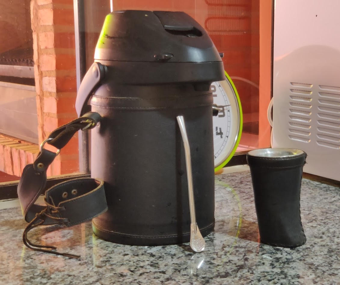
For my individual assignment I wanted to build a table for my tereré set. But first, let me explain what that means. Tereré is a traditional cold beverage in Paraguay, which is made from the yerba mate plant. You probably know Mate, which is a similar “hot water” version of this beverage and is commonly drunk in Argentina and Uruguay. Coming back to tereré… the yerba mate is poured into a cup called Guampa, then cold water is added - usually stored in a thermos - and it is drunk through a metal straw called a bombilla. So, a typical tereré set consists in a Guampa, a bombilla and a Thermos. If you visit Paraguay you’ll be amazed to see every type of Paraguayan carrying their terere set during all times.
Drinking tereré is one of the most important social customs of Paraguay, and it is really common to participate from a round of tereré with friends or family. Before COVID-19, you’d share the same guampa with all members of the tereré round but for obvious reasons this changed.

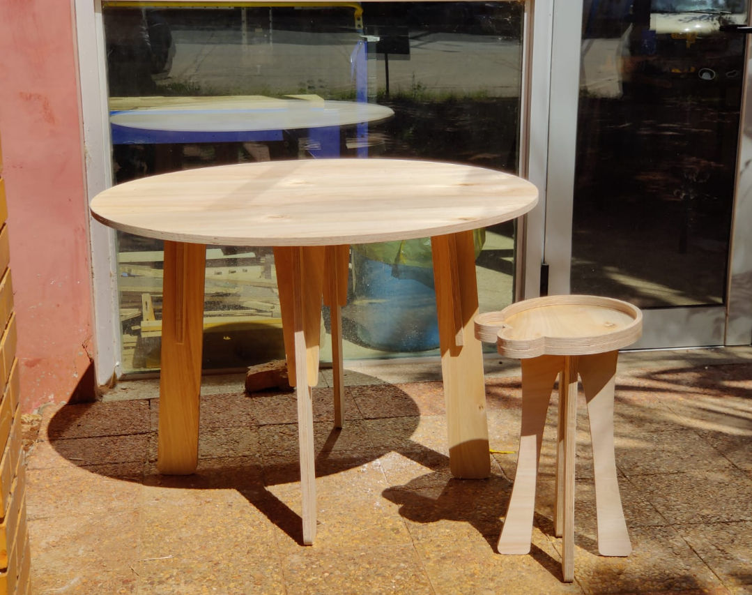
For this reason, I wanted to build a terere table with space for at least 2 guampas in order to “safely” drink tereré with your best friends.
Designing something BIG
I had never designed/fabricated furniture before and I didn’t know how to start. Fortunately I found this 3 part guide for designing and preparing a BIG table for CNC machining.
Something to take into account is that tereré tables aren’t too tall (~50 centimeters), and the diameter is similar to the diameter of a thermos (~ 30 centimeters). I’m not sure if this table alone qualifies for this assignment so I decided to make both the Tereré table and the Table that I prepared while following the guide.
We all decided to use sheets of Plywood in our assignments. The sheets available had the following dimentions:
- Height: 2440 mm
- Width: 1220 mm
- Thickness: ~18 mm
In both cases, I used parametric design to be able to easily adapt my models in case the tickness of the material wasn’t accurate enough.
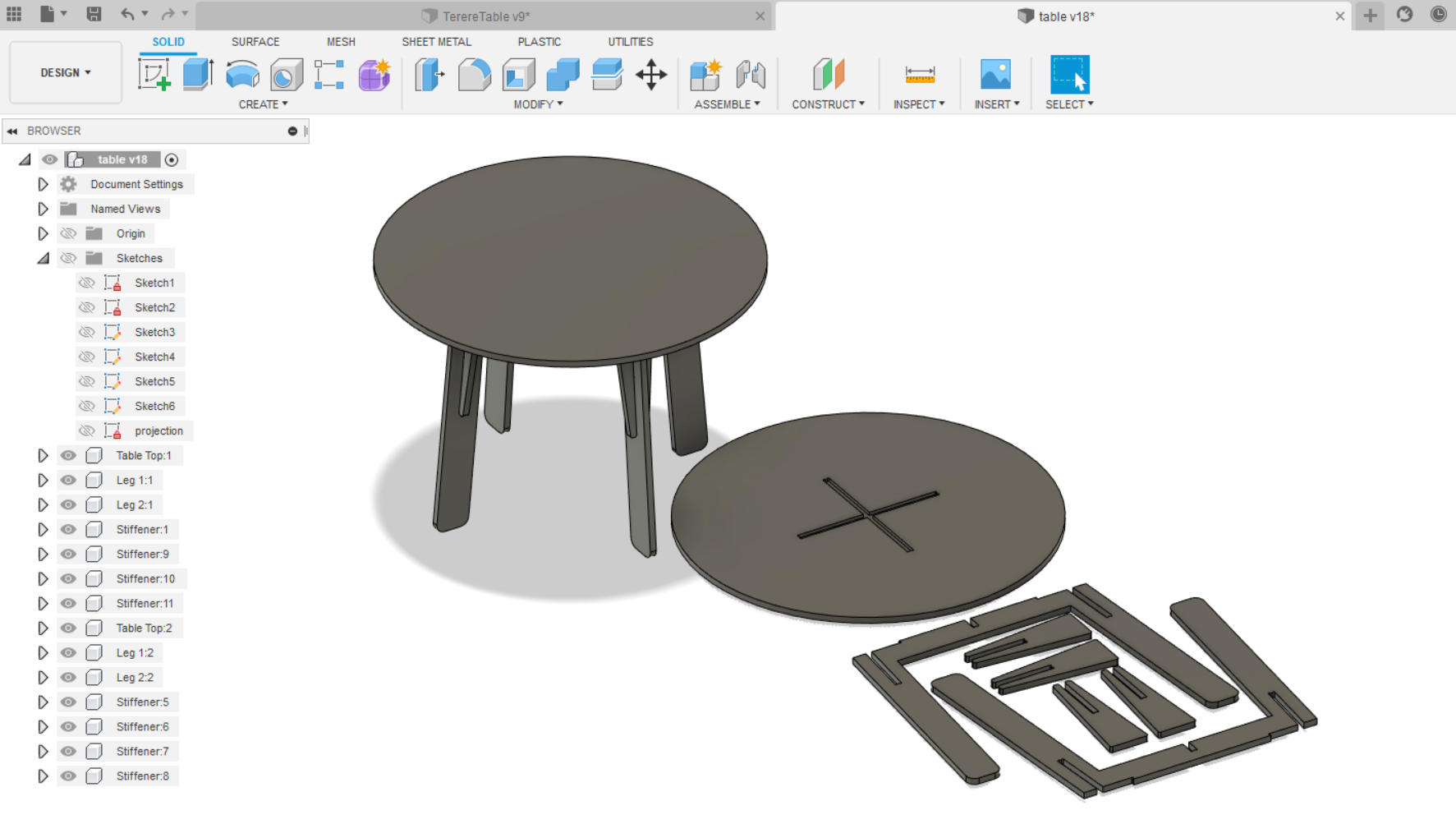
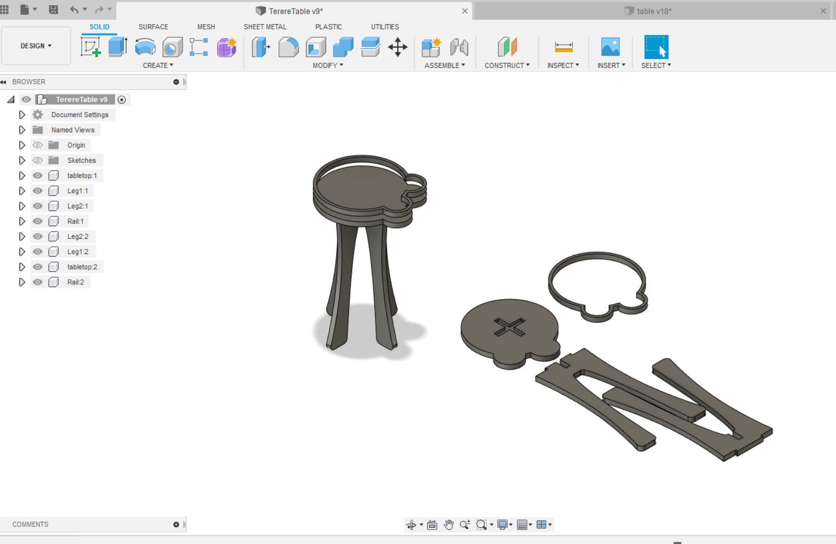
Once I finished the base designs for both objects, I proceeded to create the parts layout. In order to do that I:
- Created copies of each components in the designs.
- Sketched a rectangle using the same dimentions of the plywood sheet
- Aligned/moved the bottom faces of the components to that sketch.
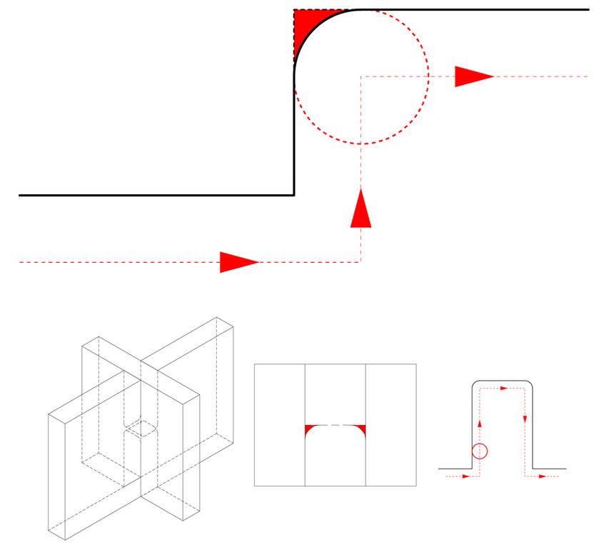
While following the guide I came across a design consideration that must be taken into account before exporting the parts: Corner treatment. Outside corners can be sharp, inside corners must be rounded. Since a round end mill is doing the cutting, the radius of any inside corner will always match the radius of the end mill (there’s no way to get sharp inside corners with an end mill on a 3-Axis CNC). For this reason, you cannot leave rectangular geometry as-is after designing a flat pack object and fit the parts together as desired.
Here are some alternatives:
- OUTSIDE FILLETS: The end mill travels outside the corner by a distance that’s equal to the radius of the bit, allowing the end of each cut to sit flush against the other (the fillet is visible after the parts are assembled).
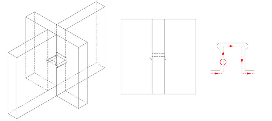
- INSIDE FILLETS: The difference with OUTSIDE FILLETS is that the fillet is cut into the short end of the cut. This kind of joint works well structurally speaking and is invisible once the parts are assembled (bad idea if the material is too thin as compared to the end mill).
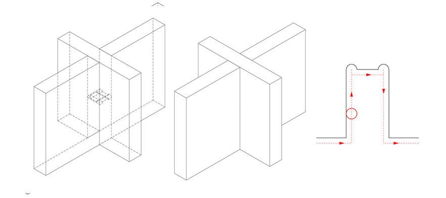
- DOGBONE FILLETS: The end mill travels outside the corner at an angle so that the cut is made equally on each leg of the cutout (Less material is cut and it can be done automatically using a script).
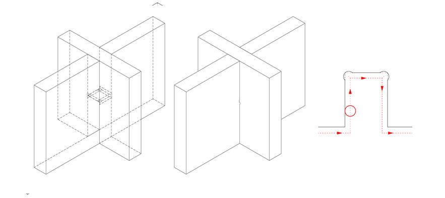
Inside fillets are ok for both designs since I plan to use the 1/4 inch end mill. To add the inside fillets I went to sketch mode in Fusion 360 and added 2 point circles to the rectangular ends using the diameter of the 1/4 inch mill.
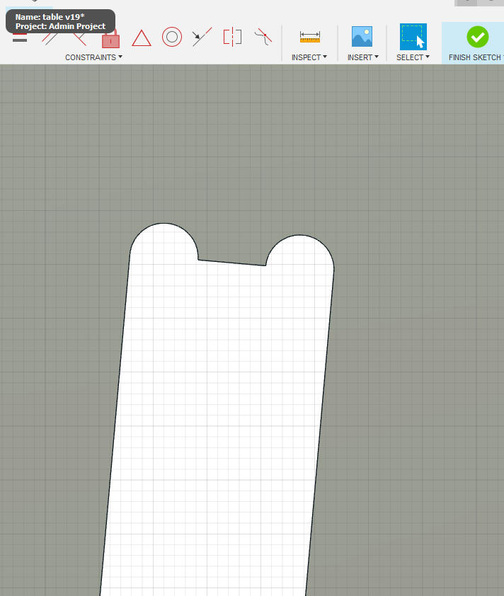
Then I created a new sketch in both designs and created a projection of the top faces of each components into the plywood sheet sketch. Finally I exported these sketches to two DXF files.
Preparing the CAM-toolpath
I used VCarve Pro to translate the design I made into instructions that the CNC router can use.
First, I created a new document and set up the main properties (Including the dimensions of the plywood sheet).
Before importing the DXF files into VCarve Pro I had to update my materialThickness variable on both designs to add an additional millimeter, because the actual thickness of the plywood sheet varied between 18 and 19 millimeters. I had to regenerate my DXF files after changing the value of this variable.
Then, I imported both DXF files and re arranged the different parts in the plywood. In some cases, I found open vectors (that is, some parts/components were fragmented in separated groups of lines). I used the join vector tool to fix the open vectors.
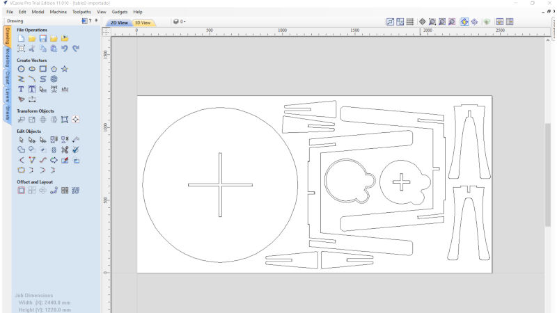
Then I proceeded to prepare the toolpaths. As a result, I created 4 different toolpaths:
- Pockets: The pockets on the underside of both tables. In this case I used a cut depth of 9 mm.
- Profile 1: Tool path to cut out the profiles of all the table pieces. This time I cutted a depth of 18 mm and performed cuts outside of the line. Tabs were used.
- Profile 2: Tool path to cut out the inner side of the terere table rail. Used a cut depth of 18 mm and performed cuts inside of the line.
- Profile 3: Tool path to cut out the outer side of the terere table rail. Used a cut depth of 18 mm and performed cuts outside of the line. Tabs were used.
As I mentioned before, in all cases I used a 1/4 inch end mill. Additionally, the number of passes used in all cases was 3.
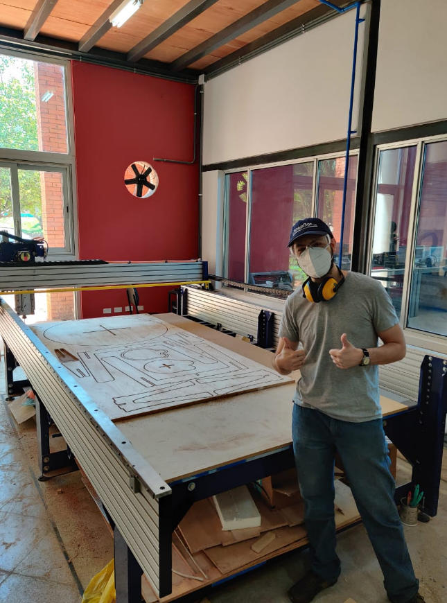
Fabrication
To start cutting the toolpaths I followed the same steps described in the Usage section and let the shopbot run for a while. According to the logs generated after wach toolpath execution this is the elapsed time:
- Pockets: 00:03:26
- Profile 1: 00:23:07
- Profile 2: 00:01:59
- Profile 3: 00:02:18
It took around 30 minutes in total to cut these toolpaths.
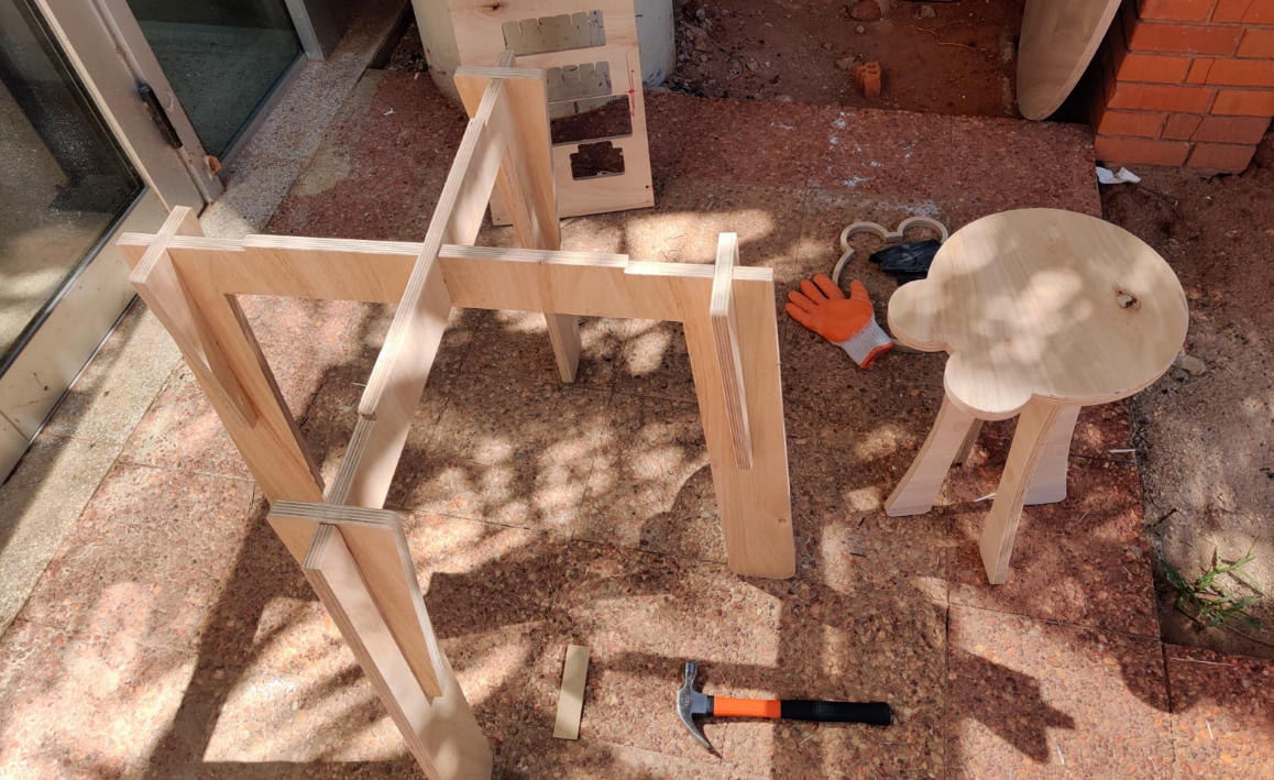
Finally, I put some gloves and followed these steps:
- Removed the parts from the plywood sheet.
- Sanded the edges of all parts.
- Assembled all parts with the help of a hammer.
- HERO SHOT!