14. Networking and Communications
Plan this week is to add a couple of peripheral boards to my Echo board from Electronic Design week.
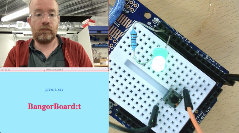
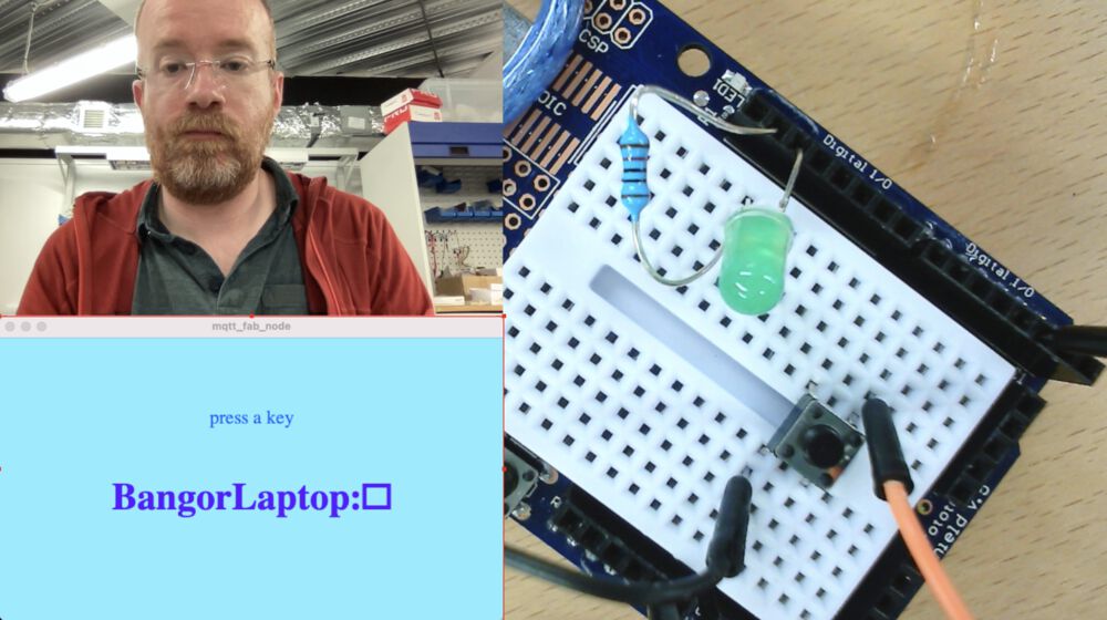
For Group Work I have coded a demonstration of MQTT using Arduino, Processing and an open public MQTT server.
Group Work
Using these sketches you can toggle an LED from anywhere in the world. Just press ‘t’, for toggle.
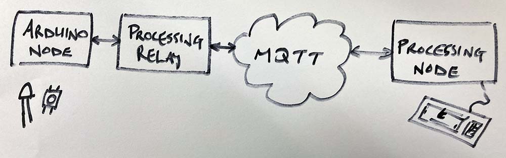
Arduino Peripheral Sketch Processing relay for Arduino Processing Node
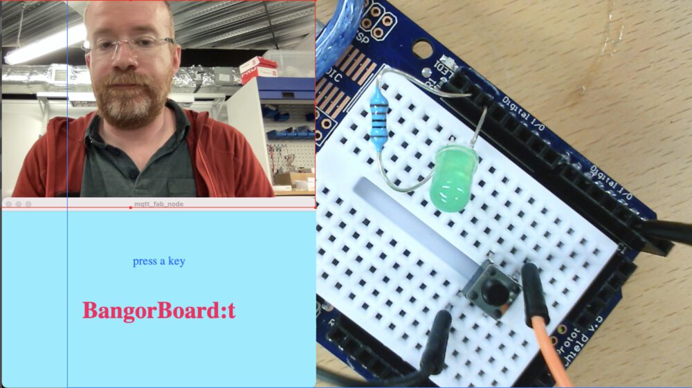
Images here show me playing with it on my laptop, pinging messages to the off site MQTT server.
Global Demo
This simple application of MQTT was picked up by Neil and used as a live demo during the following weeks lecture. Lecture video at timestamp 17:50. It was quite fun seeing it actually work with successful toggles from South Korea and more from the US.
In the screen shot you can see my little face, the LED lit up, and the indication that the keypress that lit up the LED came from Seoul, South Korea. The key press kindly provided by Miriam

We learned that with very cheap bits of kit you can make global machines.
README
As everyone’s echo board is different, I’ve written the example node in portable Arduino code. All that needs to be changed is the pin reference for an LED and a Button. Upload the Arduino sketch to your board.
Warning: You will not be able to program your Arduino if you are running the Relay at the same time.
The Processing code was written using version 4.0b7, it should run on earlier versions. There are two processing sketches, the first acts as a relay for your Arduino code, passing messages to and from the internet. The second is a node that send and receives messages, use this to toggle any connected LED by typing ‘t’ on your keyboard.
To get the processing sketches to run you will need to Install the MQTT library:
In Processing menus: Sketch > Import Library… > Add Library… Search for MQTT and hit Install.
You may need to pay attention to the Relay console output and make sure that the Serial connection is picking out the right serial port to talk to your Arduino or similar board. On my Mac it was third in the list:
/dev/cu.Bluetooth-Incoming-Port /dev/cu.debug-console /dev/cu.usbmodem12401
so the relevant line looks like:
  /*** Set this so it picks up your board ***/
  myPort = new Serial(this, Serial.list()[2], 9600);
  /*****/
Note on naming
In correct networking terminology Relay may be a bit of a misnomer. As the ‘relay’ sketch is passing messages, directly translating between networks, it should possibly be called a proxy.
Individual Work
A simple serial network.
Hardware
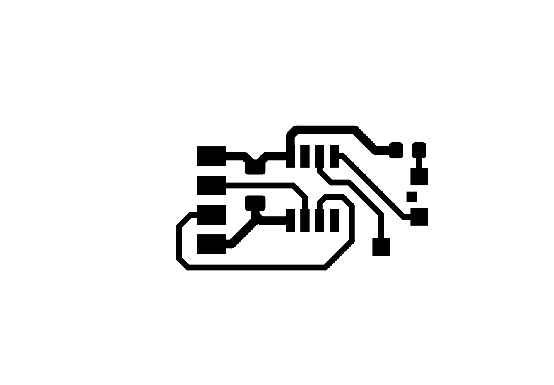
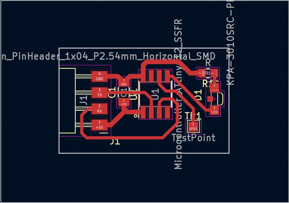
For this work we’ll make use of our Echo board as the Controller. This has a button and an LED.
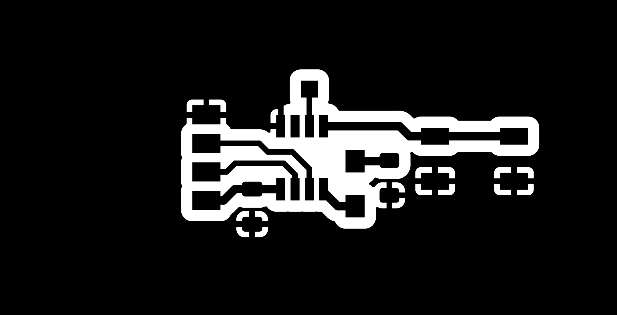

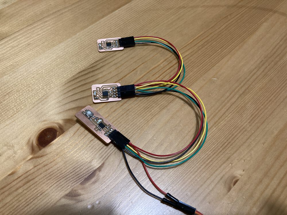
For the two peripheral nodes we’ll make some boards with just an LED and an ATTINY412:

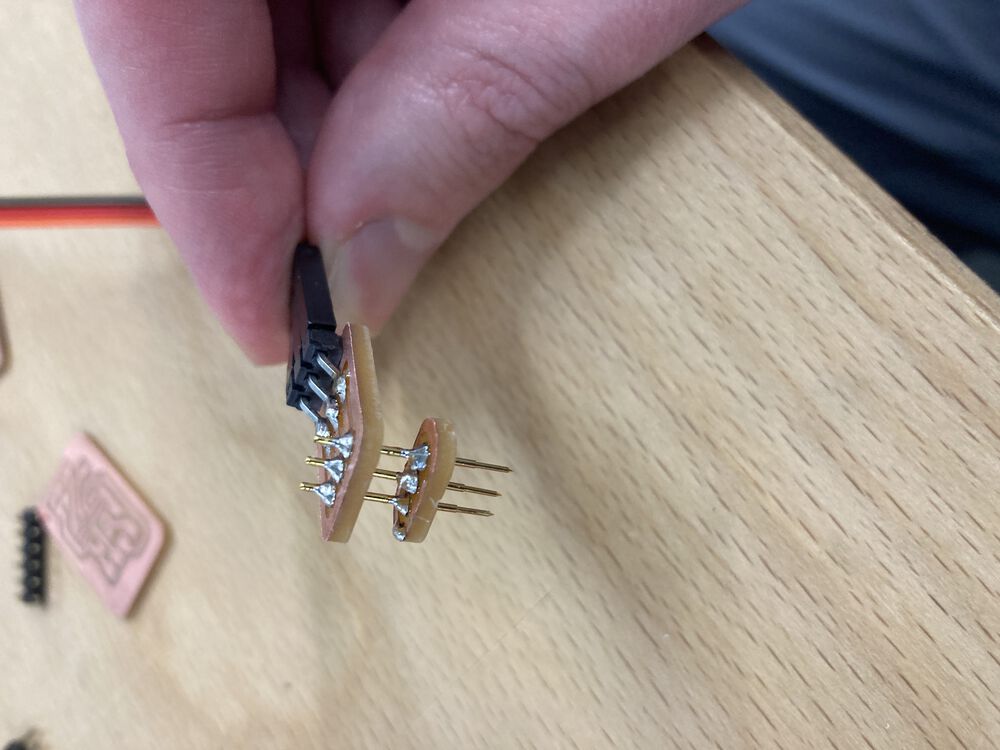
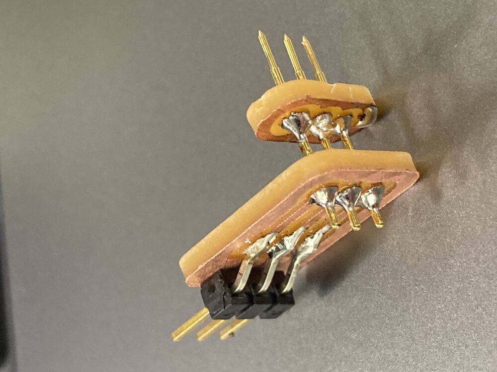
To save on connectors over time, I’ve decided to make up a little pogo pin adapter, see the assembly below:

The boards are put onto a four wire bus: 5V, GND, Controller Tx, Controller Rx.
Software Principle
We are wiring together straight serial ports as a bus. This is usually not recommended, the Transmit hardware may not be protected against this.
One transmitter to many receivers holds few risks to the hardware directly, however all recipients need to be aware and able to handle the fact that they may be receiving messages not destined for them. That is, a raw bit of hardware expecting to have a serial connection to itself may interpret the received bytes and do damage to itself. On the many transmitters to one receiver side, we have more of an issue. To make it work we need all transmitters to set themselves electrically as inputs or tristate/floating. The Tx line of the peripheral is only set to output for the explicit transmission, hopefully where the protocol leaves no scope for a clash on the bus, then returns to a passive state.
You can see in Neil’s example the atomic nature of transmission where writing to the serial pin is bracketed by direction setting, output then input:
output(serial_direction, serial_pin_out);
 ... writing stuff out ...
input(serial_direction, serial_pin_out);
Where the following macros are used to set and unset a bit in the Data Direction Register:
#define output(directions,pin) (directions |= pin) // set port direction for output
#define input(directions,pin) (directions &= (~pin)) // set port direction for input
With more time we would investigate the Multi-processor Communication mode. (See Attiny412 datasheet section 24.3.2.10)
For now we’ll try manipulating the Tx pin data direction to do similar to the code above.
Software Implementation
For a first attempt we used the native hardware serial to see what would happen. Attempting to set the Tx line to be input. It was a failed attempt. Further reading in the Attiny412 data sheet, section: 24.3.2.3 Data Transmission - USART Transmitter, tells us that the UART takes over the normal operation of the port. So regular writes to DDR are basically ignored. To enable us to tristate the Tx line we’d need to disable the UART defeating the overall object of the code.
The code above works if there is a single peripheral node, not if there are more than one on the bus. To make this work, as everyone assured me, you need to use the Software Serial Library, now I know why.
The resulting code base is made up of two Arduino Sketches:
The control node will talk to two nodes at address ‘0’ and address ‘1’. This would need to be updated for a larger network.
A long press of the button will change the node that is being addressed, you’ll also get a double flash of the LED.
A short press will toggle the LED on the addressed peripheral node, a single flash denotes an Ack received from the peripheral node.
Beside looking for short or long presses the control node code also debounces the input.
The Peripheral node will toggle the state of it’s LED in response to seeing it’s address on the bus and send an Ack, ‘a’, to the control node. The transmission will be an atomic style action changing the data direction to output for the duration of the transmission only.
Manufacturing Practice
A board a day keeps the Doctor at bay? Practice is improving both design and reliability of the milling.
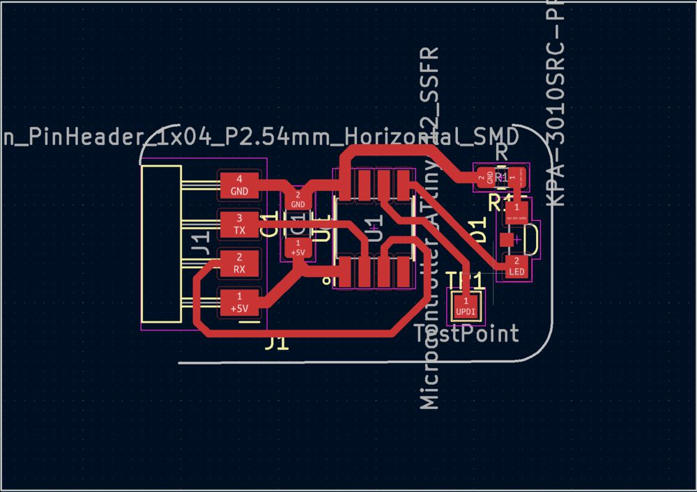
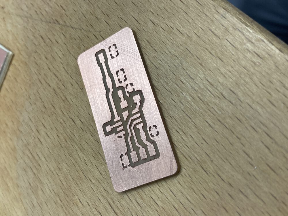
Outlines with curves Issue
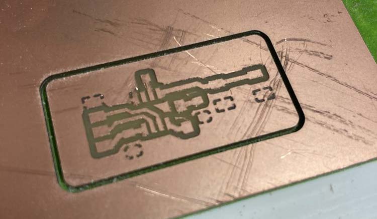
I decided that square was so last week and that rounded corners is where it’s at. My first attempt was to use curves and lines in KiCAD. However the paths that were exported could not be joined and filled by Inkscape. A round trip to Illustrator seemed to do the trick on merging the paths, but the file size seemed to get messed up. Without noticing this fact the first trial created a miss-match in traces and outline when milled:
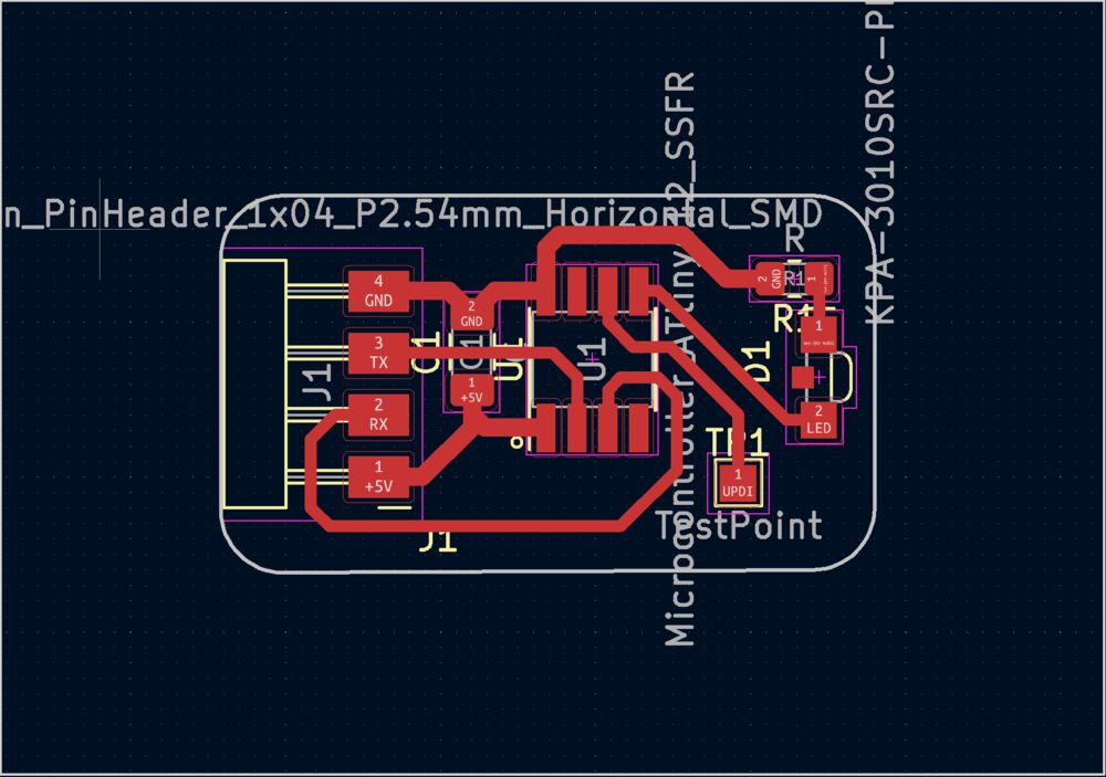
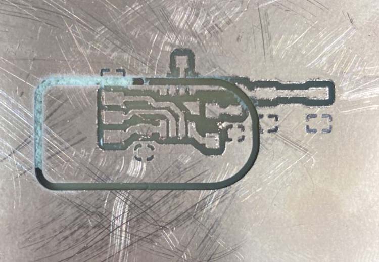
The work around is to export a reference rectangle from KiCAD and use that to draw a nice outline in Inkscape.
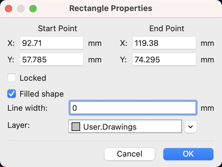
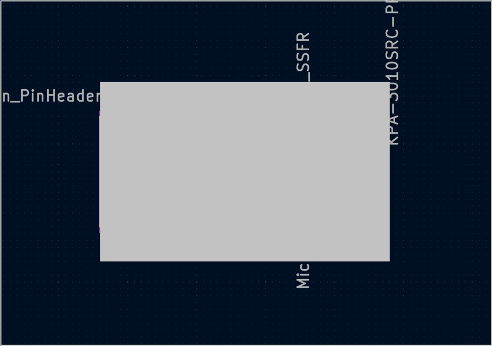
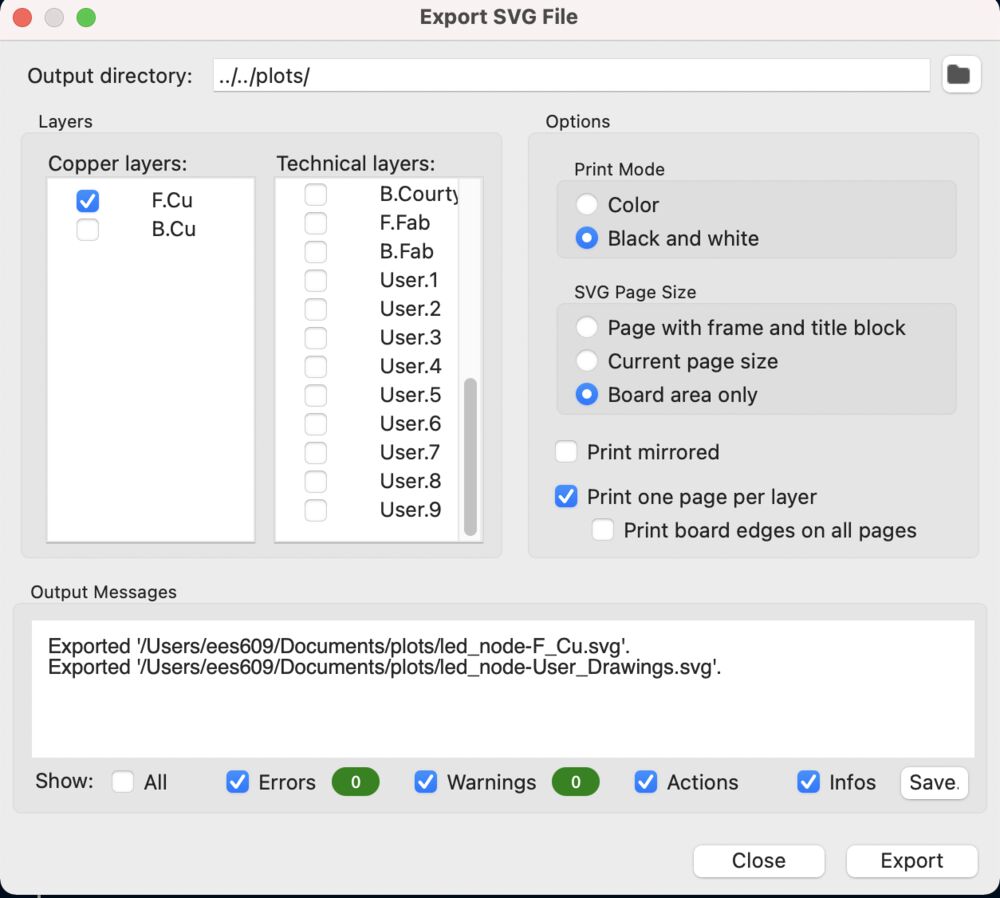
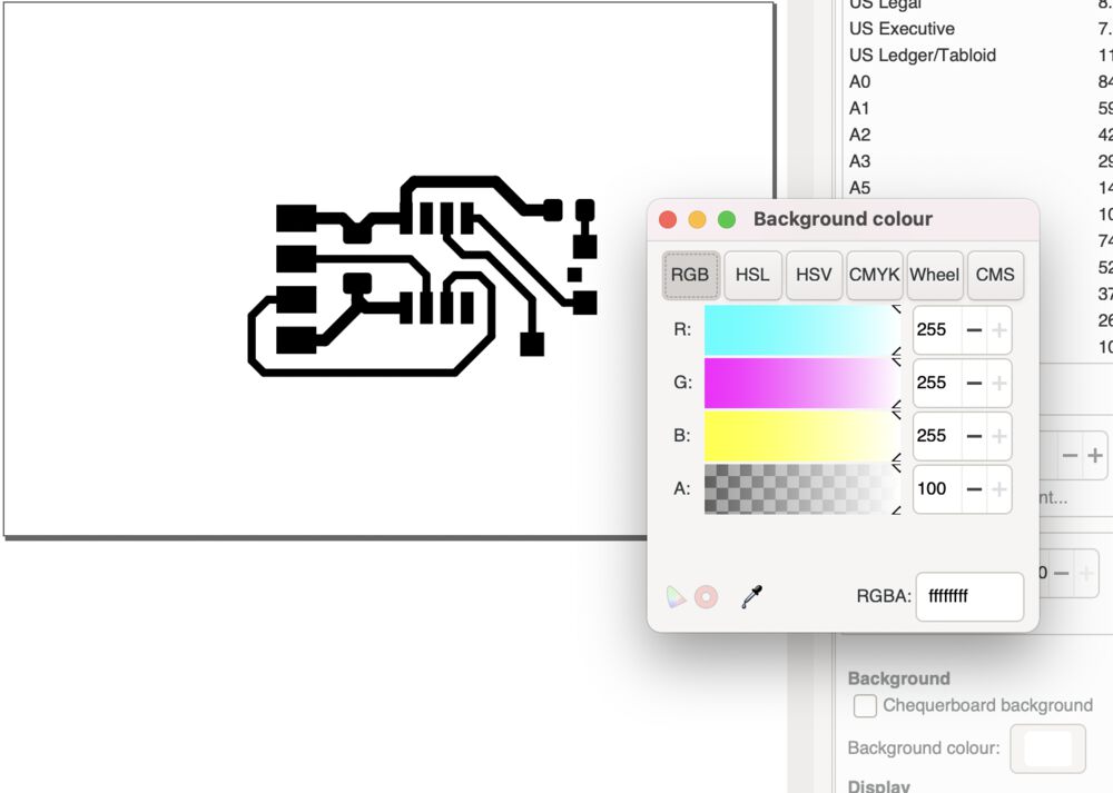
Remembering that we need to set the background to white so that we don’t have issues in modsproject with transparencies. Before drawing the nice outlines, a rectangle with the corners dragged round using the node tool.


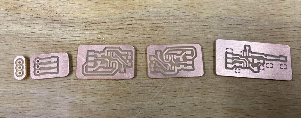
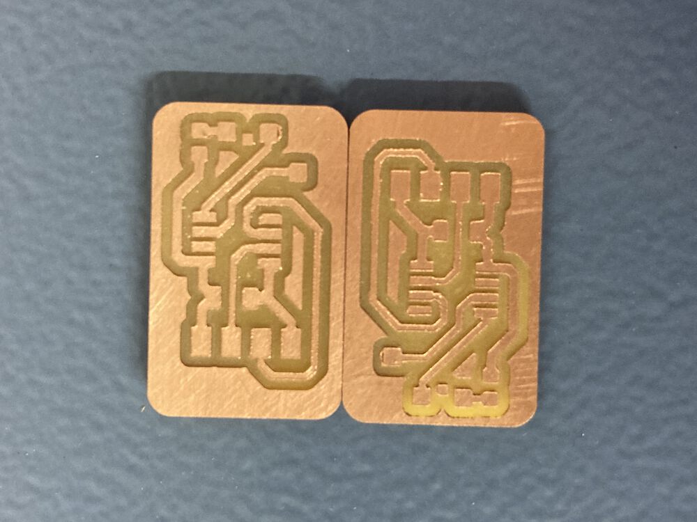
We now get matching images and a nice board with rounded corners. Scuff marks are from de-burring the board with a knife.
Some shots of our boards for this week, cleaned up ready for soldering.
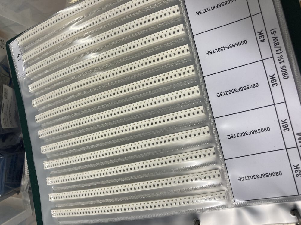
Note that we use 0805 for the LED current limiter as we have a resistor kit in the lab, this allows us to pick out almost any value.

our finished network again:
Hero Video
Here we can see the LEDs on the peripheral nodes being toggled by button presses on the controller.
Pogo Adapter
I don’t like having extra connectors on the board for flashing code, but holding standard jumper wires against pads is not all that convenient, so I produced this little pogo adapter. At most we’ll need Power, GND and UPDI. I can wire up the UPDI connector in any order. In many situations the board is already powered and I just need UPDI through this adapter.