16. Wildcard Week
This week the plan is do to a composite for the final project.
The steps this week are:
- to mock-up the final project enclosure.
- Design and mill the mold required for a bag press.
- Layup a wood veneer laminate.
Mock-up
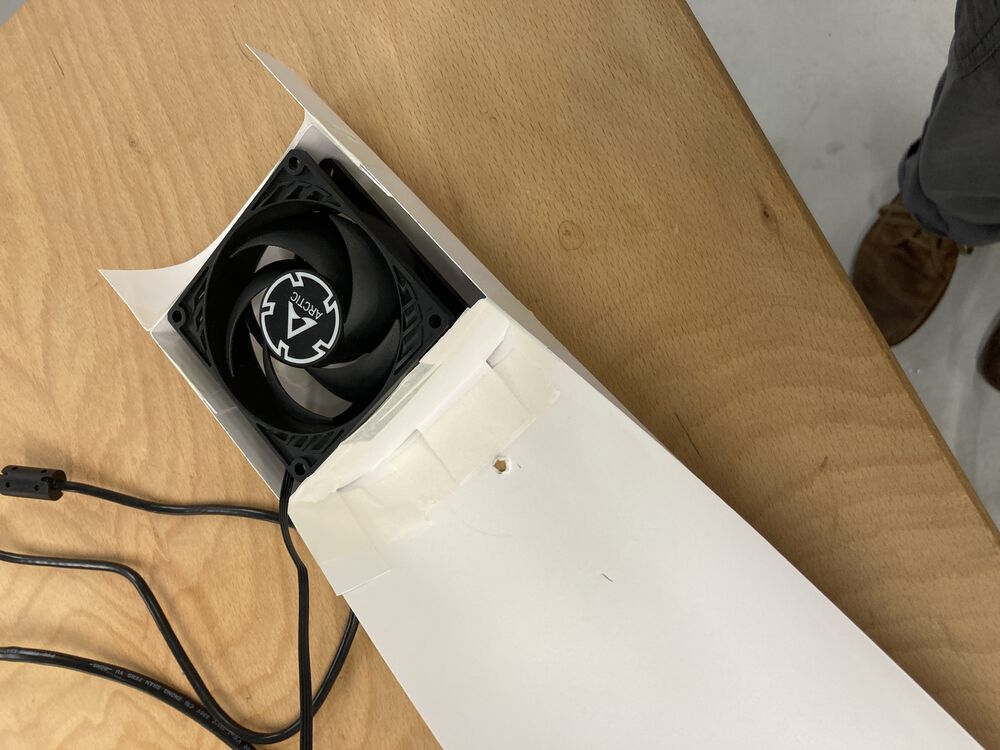
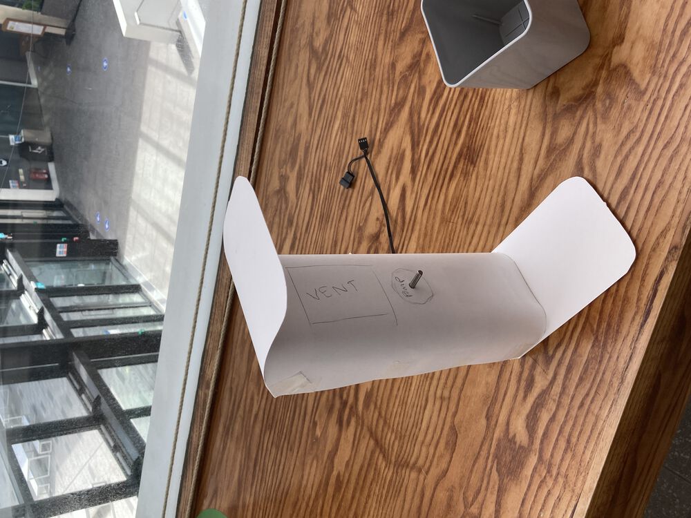
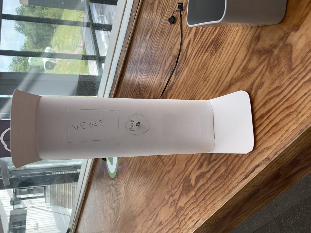
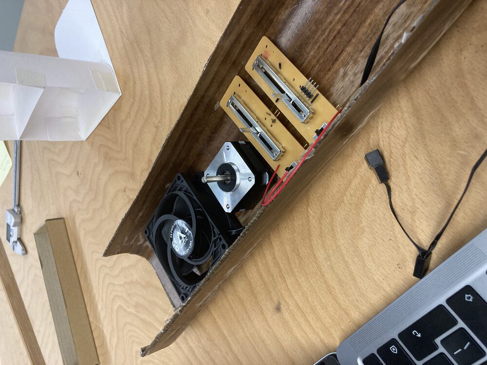
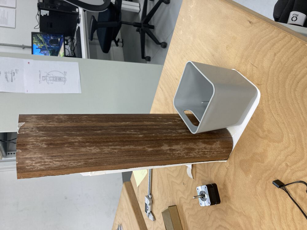
We had some idea of the final form from our initial sketch. Refining the form was done in the real world with some card, taking the components that we had and the dimensions of the raw material as hard constraints.

Taking the real guts and some card:
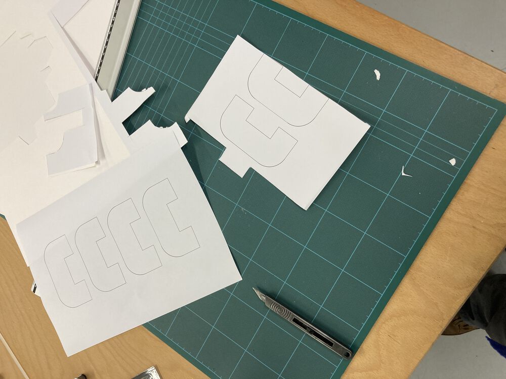
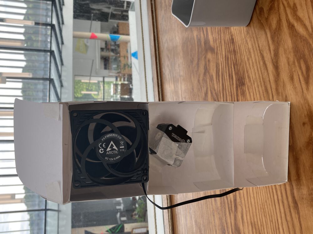
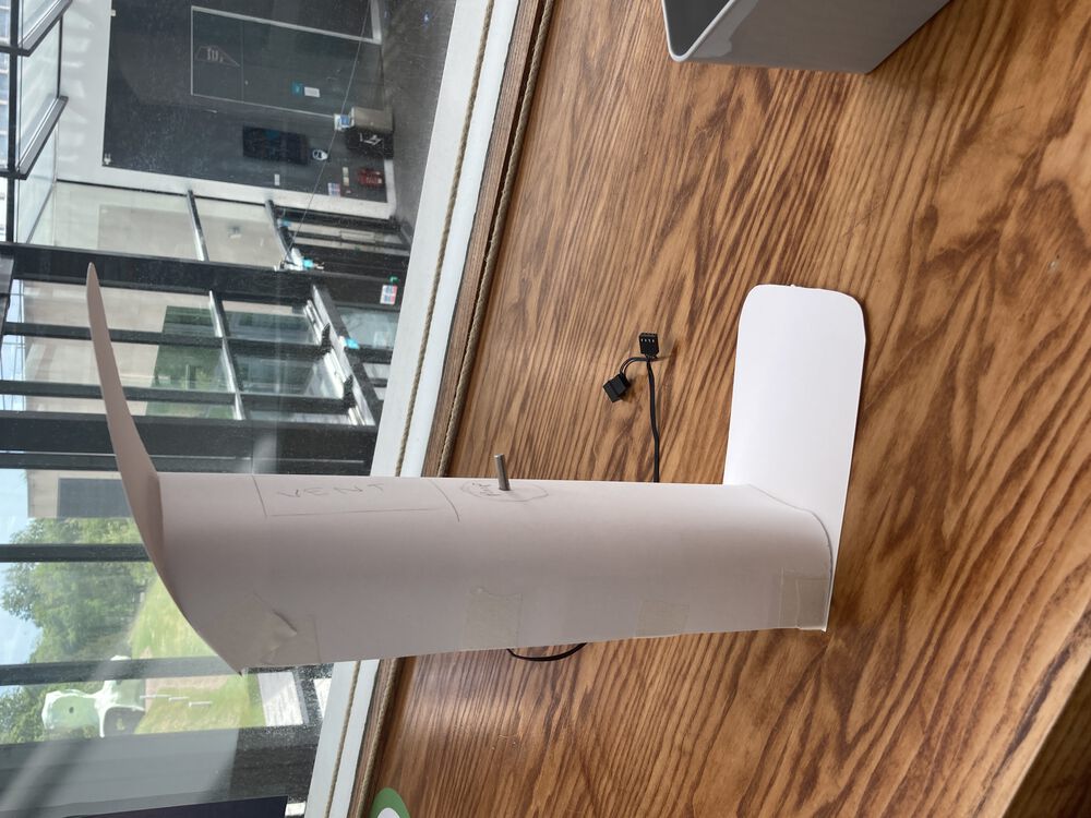
At this point we were already considering how to make it and started to include defined profiles to hold the curve, that were printed onto paper and glued to card. The curves were defined according to the constraints we were discovering during the mocking-up process and capturing in Fusion 360.

Test Coupon
We dived straight in with project parts, so there was no preliminary test piece. However there was some excess resin in our first mix so we did make an extra piece, and we also have offcuts.
Looking closely at a sawn and sanded edge we can see that we have a good fill of resin in the flax core. The wood veneers look very thin in profile:

We have offcuts with and across the grain of the veneer, we can see that it’s a bit more flexible across the veneer as you might expect, tested with a carefully calibrated grip…


And a test piece just taped to a card tube to form it, shows the dynamic properties of the finished material:
Design parts for the mold
Developing the mock-up was a mixed process of craft and CAD. So I already had the curve for the form available in Fusion 360. Rather than try and 3D mill the form, it was sliced up so that a simple profile machining operation could be used. To align the parts they all had a cut out in the bottom face that would mate with a ‘key’. If there were fewer layers we might have considered a dowel, but it would have been difficult to drive through so many layers and get a good fit. The images here show the CAD output, a single curved piece, the ‘key’, where you can see the slot in the bottom of the curved piece that mates with the simple key, and the assembly used to manufacture the curved sections. Where in Fusion you start a new empty design and in the file tree right click and ‘Insert into Current Design’.


Files
Files that were used to manufacture forms for the composite parts detailed in this weeks assignment.
Curved Part - Fusion file Key - Fusion file Curved Part - stl Key - stl
Milling the parts
Starting to get familiar with the router, still making a few mistakes, see below. Result is a tight push fit. I don’t think I’ll need to glue the thing together in use.
See Computer-Controlled Machining for details of how to use the machine.

Above you can see the simulation that was run before final prep for milling.


Remembered to make the depth of the key material thickness, but forgot to make the length a multiple of material thickness.
Milling, new lessons learned.
It’s very easy to pick the wrong Fanuc post processor. Make sure it’s the vanilla one. It was apparent that I’d picked the wrong post processor when the machine did something that was not the expected output. The correct post is the one that Fusion lists under the Fanuc vendor with a simple ‘Fanuc’ in the description column. With this post selected the machine produced the expected output.
If you’re tidying away the touch off device, coil the cable well away from the light curtain! With the job running I started to tidy up, part of that involves coiling up a cable to put it back in the toolbox. I did this too close to the machine, and managed to wave my hand through the safety light curtain.
When the light curtain stops the job, it kills the x,y,z motor drives, it does not stop the controller, it does not stop the spindle. The result will be having to restart the job from setting origins onwards. It will not allow you to ‘un-pause’ the job.
Take steps to stop the spindle with the pendant, or the stop button. Start again from the top.
Vacuum Bagging a Simple laminate
Two of the parts of my final project are laminate parts. This week we detail the method of production of a wood and cloth lamination in a bio resin.
Safety
After speaking with Jani about the risks presented by resins I decided to do a bit of extra research and also ask advice from more experienced technicians.
The main compound to be cautious of is BPA or Bisphenol A. It’s the component of the resin that hardens the plastic. The science on BPA does not seem to be definitive at this point, but it is something that has been removed from food related plastic products, eg: you may find your water bottle marketed as BPA free.
The hazard presented is that it can act in the body like a hormone, mimicking the effects of estrogen. See wikipedia article
I asked a senior tech here at Bangor to take a closer look at the SDS for the LB2 resin that we’re using for this project. He responded:
Hi John

Having read through the SD for the LB2 Epoxy Laminating Bio Resin, here are my recommendations:

- Avoid breathing fume: I recommend use of LEV, similar to extraction unit used for 3D printing. If fumes are not sufficiently controlled, respirator is required. I will source appropriate mask and provide face fitting.
- First Aid: Be aware of section 4 of the safety data sheet
- Fire Fighting measures: Section 5
- Accidental Release measures: Section 6
- Handling and Storage: Section 7
- PPE: Section 8.2 - Wear safety goggles with protective sides accordance with standard EN166/gloves/protective clothing
- Disposal Considerations: Section 13

Hope this helps
Alan
my setup to handle the laminating process takes this advice into consideration.
Once I had my setup prepared and documented I checked it with the head of health and safety in the college:
Hi John

Looks good to me

john
Closer look at SDS and TDS
There are two documents that you need to look at before handling a new chemical. The Safety Data Sheet and the Technical data sheet.
The material: LB2 resin SDS TDS
The technical data sheet gives you the instructions on how to use the resin, timings and mixing ratios. It also details the finished mechanical properties etc.

The safety data sheet tells you about the chemical contents and the hazards that they present to you.


We can see that it would be a bad idea to get any on your skin or to breathe the fumes. To handle this we have the PPE that’s appropriate and we use extraction to remove the fumes from the work area, more on the setup below.
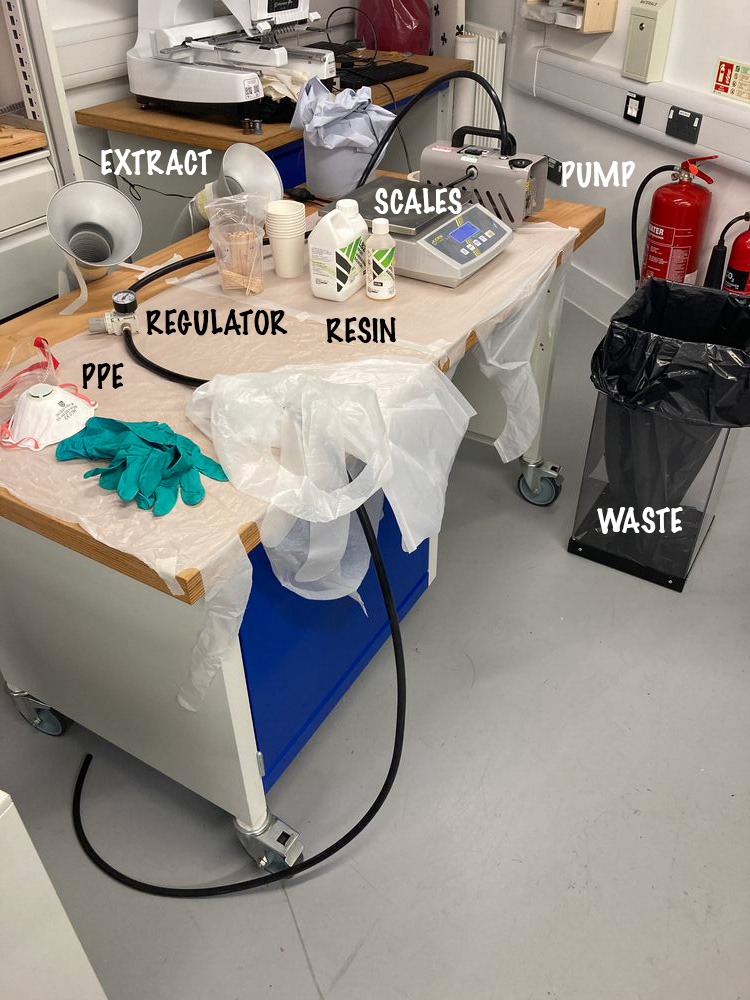
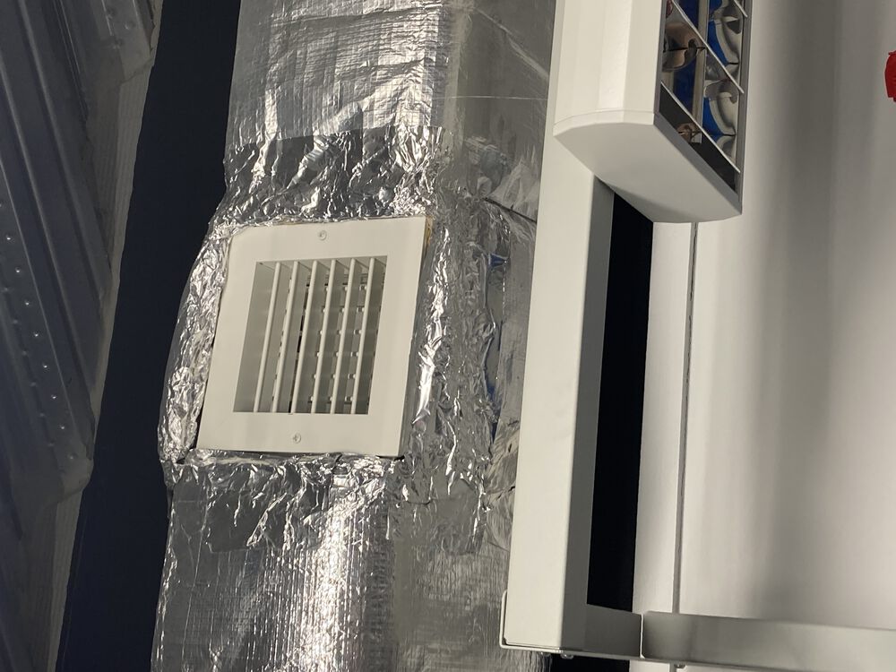
Setup
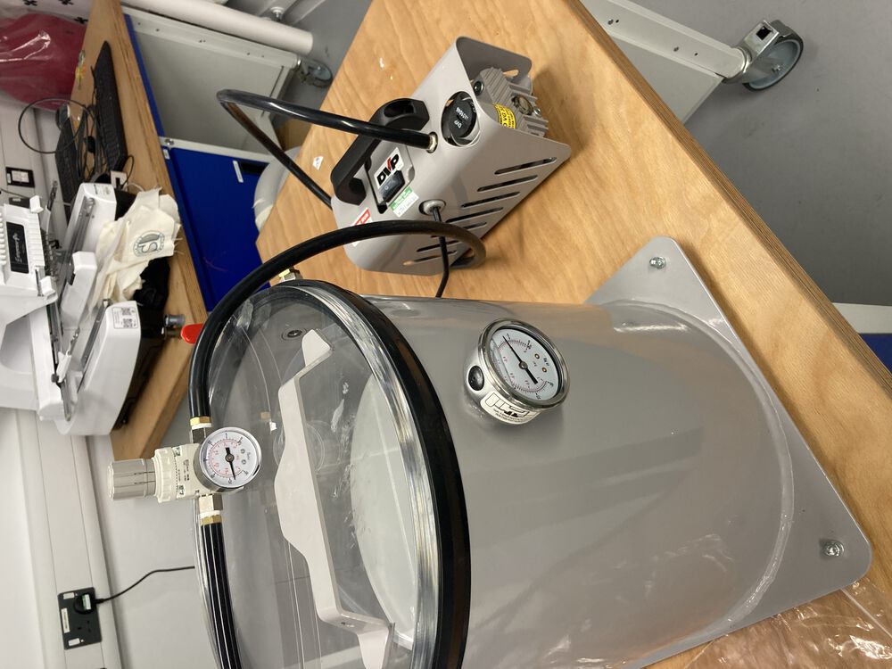
The setup is illustrated below. We have a bench covered with disposable plastic sheeting. Behind the bench and visible at the back of the workspace we have an extractor with charcoal filter. Next to the bench we have a waste-bin. The whole setup is in a room with good air exchange.
On the bench we have our vac pump that is connected to our bag though a vacuum regulator. Scales and mixing cups and implements.
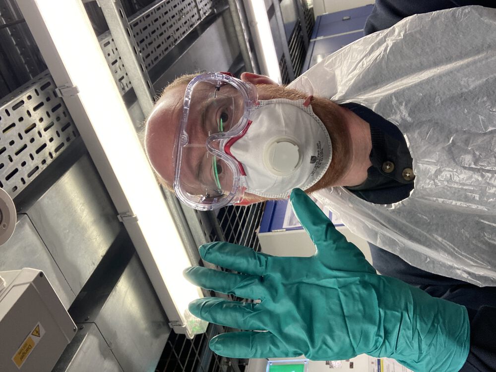
For PPE we have goggles and facemask to keep splashes out of eyes and off skin. We wear a workshop jacked/lab coat and long chemical resistant gloves. To make mess go away easily we also cover up with a disposable apron.
Mixing Siri-ously
The Resin comes in two parts. A ase material and a hardener. These need to be mixed in the ratio of 100:27. Not visible in the images, as it’s taking the images, is my mobile phone. A key part of the method. To mix up a batch of resin, we put a cup on the scales and zero out. Then add the main resin component, this is a stiff viscous fluid and hard to control the pour. Once that is portioned out we ask (for example): ‘Hey Siri, what is 72.6 times 0.27’. Siri will answer, we zero the scales and add the right amount of hardener. We can pre-define the weight of both components and get errors in weighing out both or we can calculate on the fly, hands free, and make errors in the hardener only, which is less viscous and easier to pour out accurately. Overall I think this gives us a good ratio. Did find that the scales are quite slow to update, you need to pour out slowly in small parts.
A mixed resin was poured into a second cup and mixed again before use.

Times for the resin doing things are as follows:
Initial Cure Time: 13.5 Hrs Pot Life (Typical): 20 mins Gel Time (Typical): 4.5 hrs Full Cure Time: 14 Days
Setting up the vacuum
The supplier of our vacuum bagging kit recommends that a 20% vacuum is pulled on the part. Having got good results out of this setup I concur. To set the correct fraction of vacuum we put out regulator in line and test it with the only vacuum gauge we have, in our degassing bucket.
Making a bag
A bag is made with a nylon film, sealant tape and a through-bag connector.

I marked the crease line of the bag before opening it up and applying the tape. Be careful that the tape and film are smooth. Leave tape cover on at the entrance to the bag, I came around the corner and had a tail hanging free ready to pull out and seal the bag. Getting it wrong the first time and improving it the second, put the through-bag connector at back of the bag, not near the opening.


Bag a bit creased after use, notice I kept the white tape handy to re-cover the sticky seal for bag re-use.

Layers
Before it goes in the bag here we see and example set of layers. The MDF form is wrapped in a release film. (It could also be waxed), then we have our laminate layup of wood veneer, a single layer of flax cloth and wood veneer (Just three layers of material in the layup). There’s another layer of release film on standby and a breather cloth.

The release film stops anything from gluing itself to the form or the breather. The breather layer is there to make sure that the bag doesn’t ‘seal’ itself near the through bag connector, before evacuating all the air.
Layup
Had my hands full, so no images of the active process of getting the material resin coated and in the bag.
- First, with small fragments of masking tape I attached a layer of wood to the form.
- Next, brush a thin layer of mixed resin onto the wood with a disposable foam brush.
- Add the cloth to the sticky wood
- Paint the bulk of the resin into the cloth
- On the bench paint the second layer of wood with a thin layer of resin, add to the laminate
- Tape over a release film.
- Put from into bag with breather over the top
- Seal bag and apply vacuum.
- Around the edges of the part, make sure that the bag doesn’t get trapped between the laminate and the form. If required, release the vacuum and go again.
The seal on the bag seemed to be pretty good and I turned the valve on the through-bag connector and turned off the pump.
In the bag
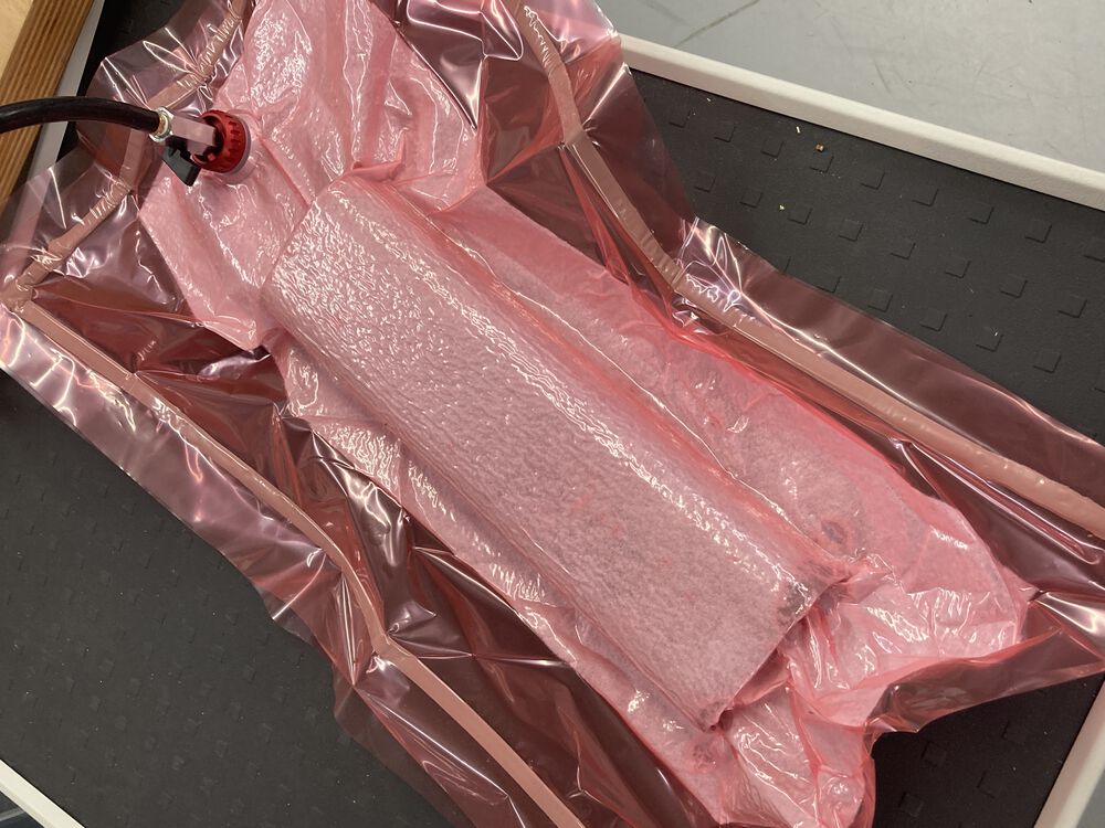
Out of the bag
Waiting a recommended 24hrs before releasing the part from the bag.
The release film seemed to do it’s job, I did use a tool just to lever the tight part of the form.
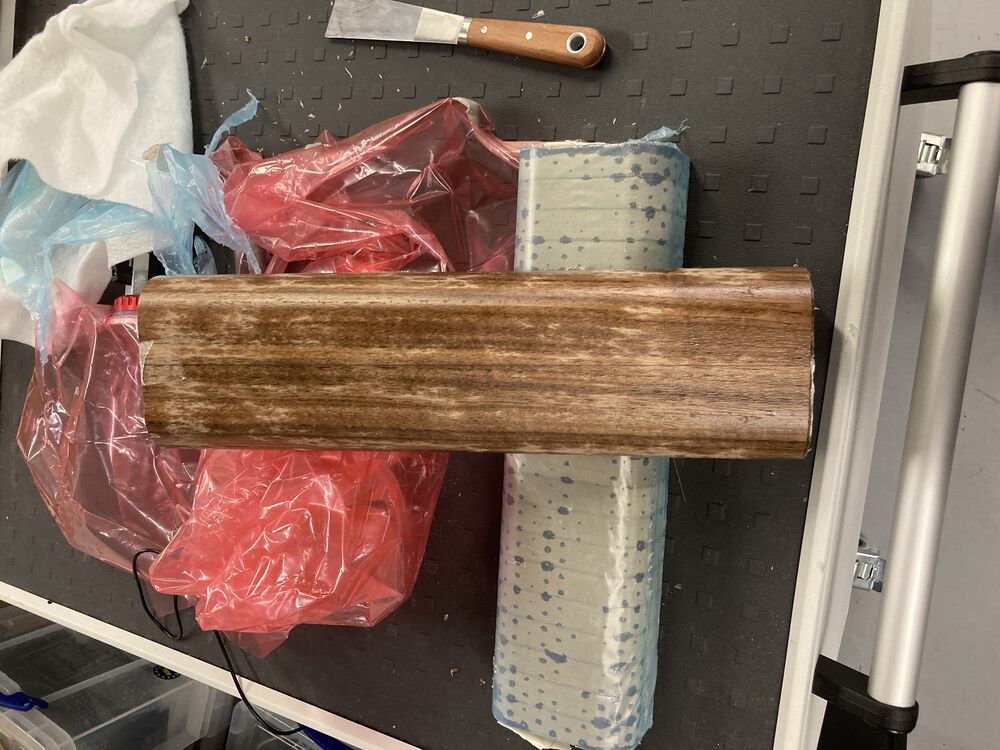
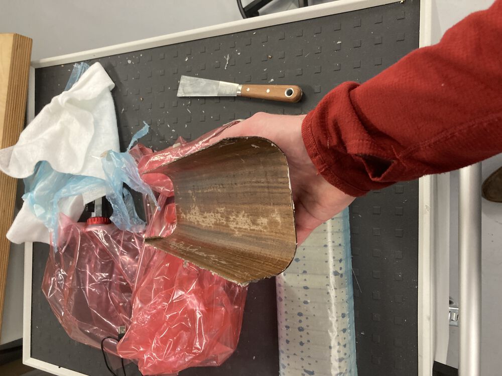
Parts seem to fit…
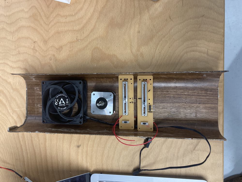
This component is part of the final project. It gets milled and shaped to mate with the second laminated part.
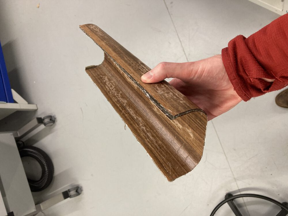
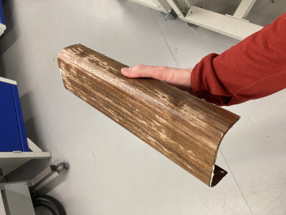
Part Deux
A second part was made with the same method. Design inspiration for the curves came from nature. At the base of the device a curve like the flare to the root at the base of a tree, and at the top something like the sweep of a branch.


Design files
Main Part - Fusion file Tenon - Fusion file Main Part - stl Tenon - stl
The form was designed to be in two parts with a floating tenon used to join them. Dowels were used to align the layers for glue-up.


The two part form was necessary to allow us to run a wire through the lamination:


Came out of the bag easily, and off the form. Notice that there is very little, if any, spring back. The finished composite mates with a 3D printed part derived from the same CAD.


Simple veneer
For some of the pump parts we also veneered some birch ply. Simple wood glue and some weight. Before laser cutting and assembly.


Tidy up
Waste materials went straight into the bin at the workstation. Gloves, apron, bench covering, disposable brush, mixing cups and sticks. This material was double bagged for disposal.
The resin components are stored in one of our chemical cupboards.