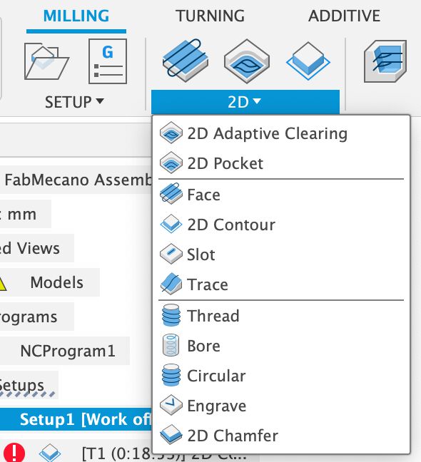
8. Computer-Controlled Machining
Summary
This week bringing a back burner to life, and developing a design for a mobile fab station with storage.
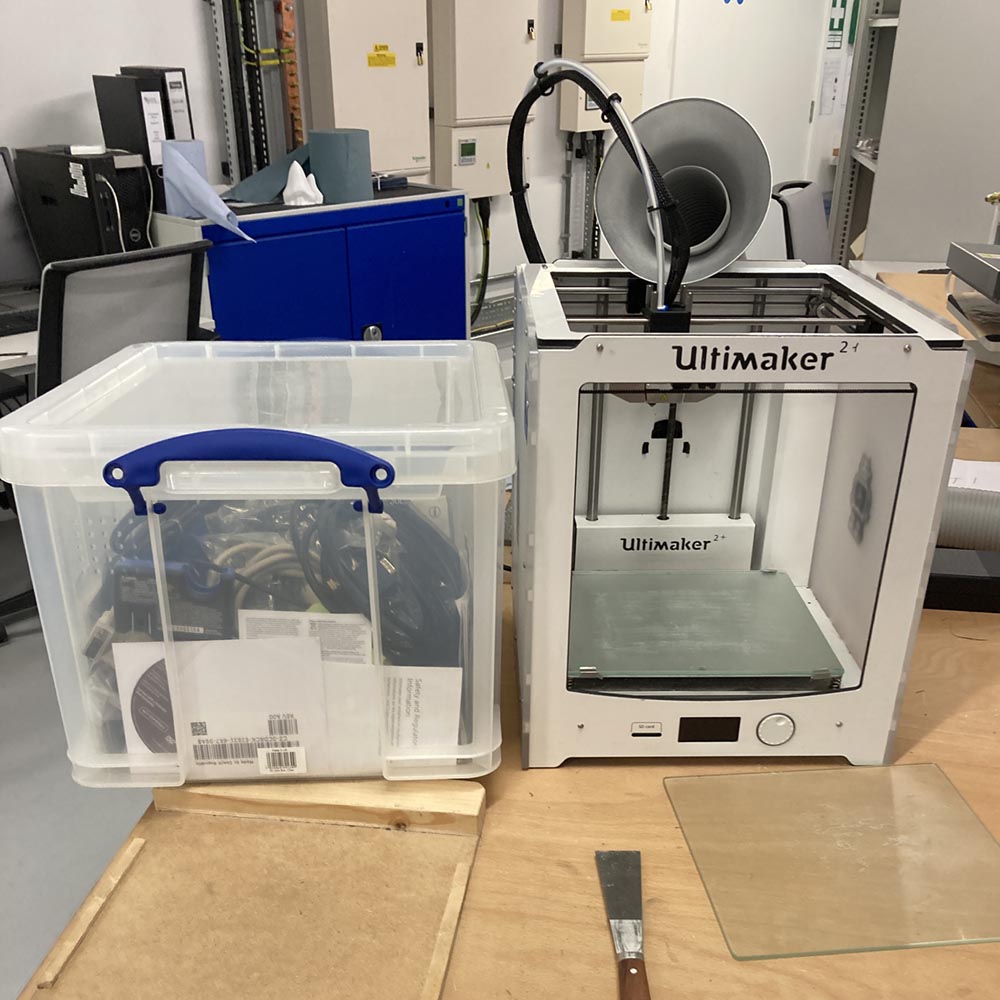
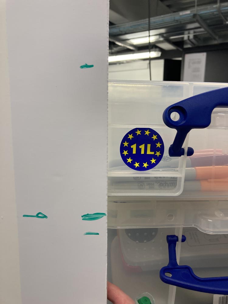
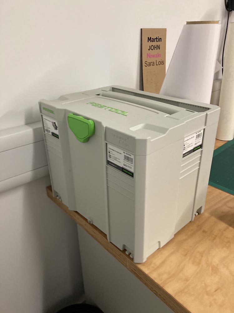
We make use of Really Useful Boxes extensively for storage here. Predominately the 35 and 18 litre version with an occasional 11 litre for smaller parts.
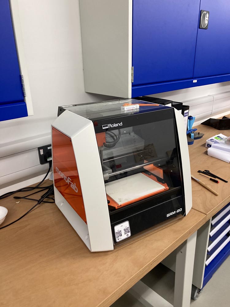
In the past I’ve noted that these boxes share a scale with many of our desktop machines, machines that I would like to make mobile.
For this project I have decided to design an assembly kit for producing mobile fab station that will accommodate a desktop fabrication machine on top at bench height, with storage underneath and the potential for ancillary equipment ducting and wiring.
Tools and Software
FreeCAD CorelDRAW - (used to drive our lasers, compile the final tiled construction set)
Trotec Speedy - Pontio fablab laser resources RouterCAM 1224
Files
FreeCAD version:
Fusion 360 version:
Link to Group Work
Reflection
It’s a big scary machine. But once you get use to it you get to a certain level of comfort, but I hope to never take it for granted.
Our working practice and the work cell that the machine is in eliminate most risk accossiated with the machine.
Development
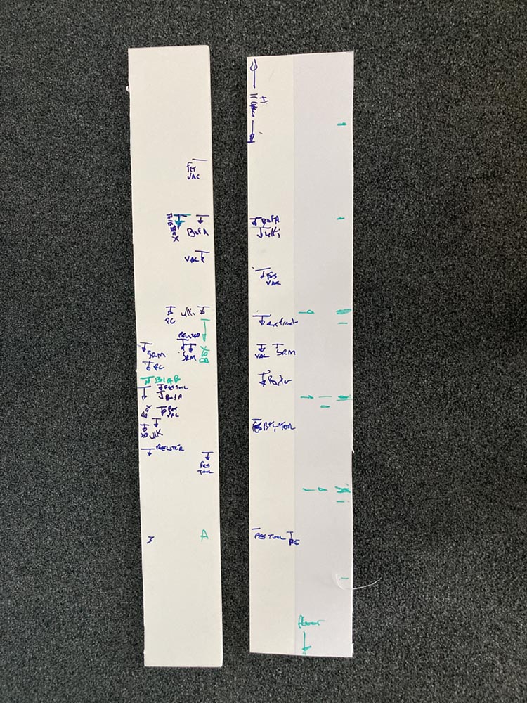
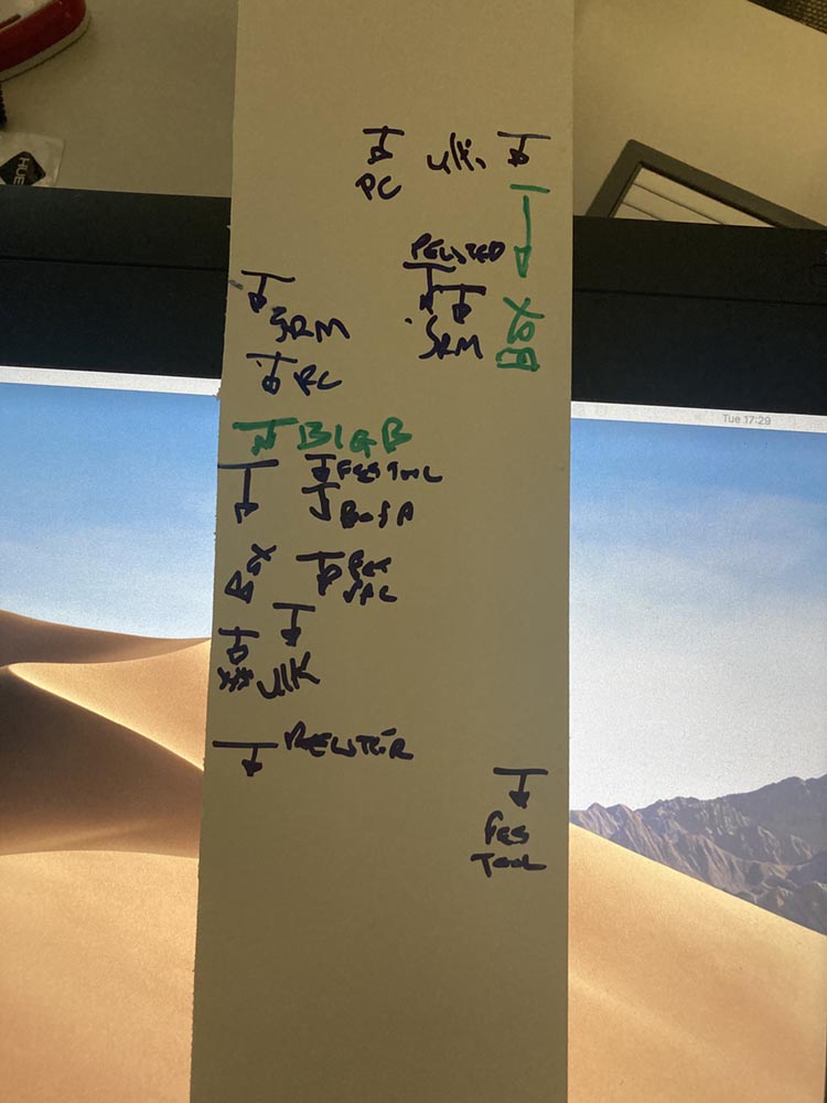
To start with play with some boxes.

 Concluding that two 35l stack well against three 18l. Adding a little space evens things up a little more, lets call 35l 3units and 18l 2units
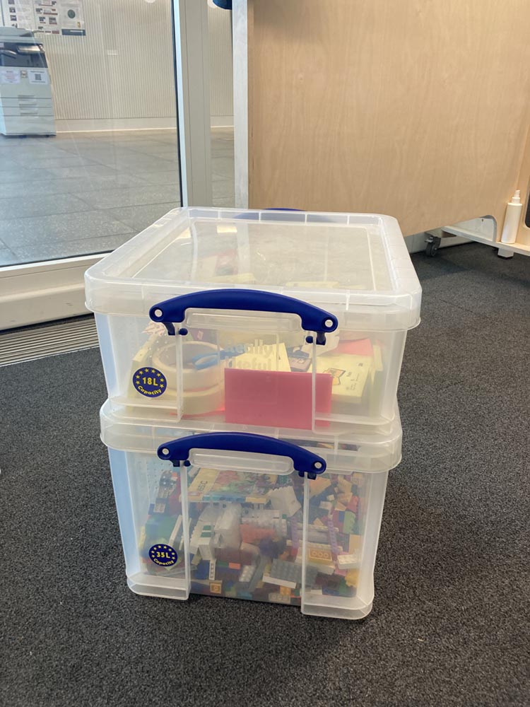
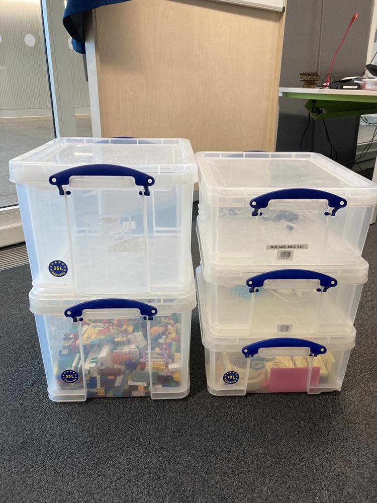
![]() and 11l is a handy 1unit
and 11l is a handy 1unit
 Exploring typical machines with a marker pen and a stick of foam board. A tight cluster emerges in width, slighly more spread out in depth, very spread out in height
 example bits of kit
Design
Move to freeCAD to get some parts designed. A flexible side that’s 6 units high. 1 box and one ducting compartment deep, a piece to stop racking, a Shelf and a top and bottom. Where possible parts are symmetrical.
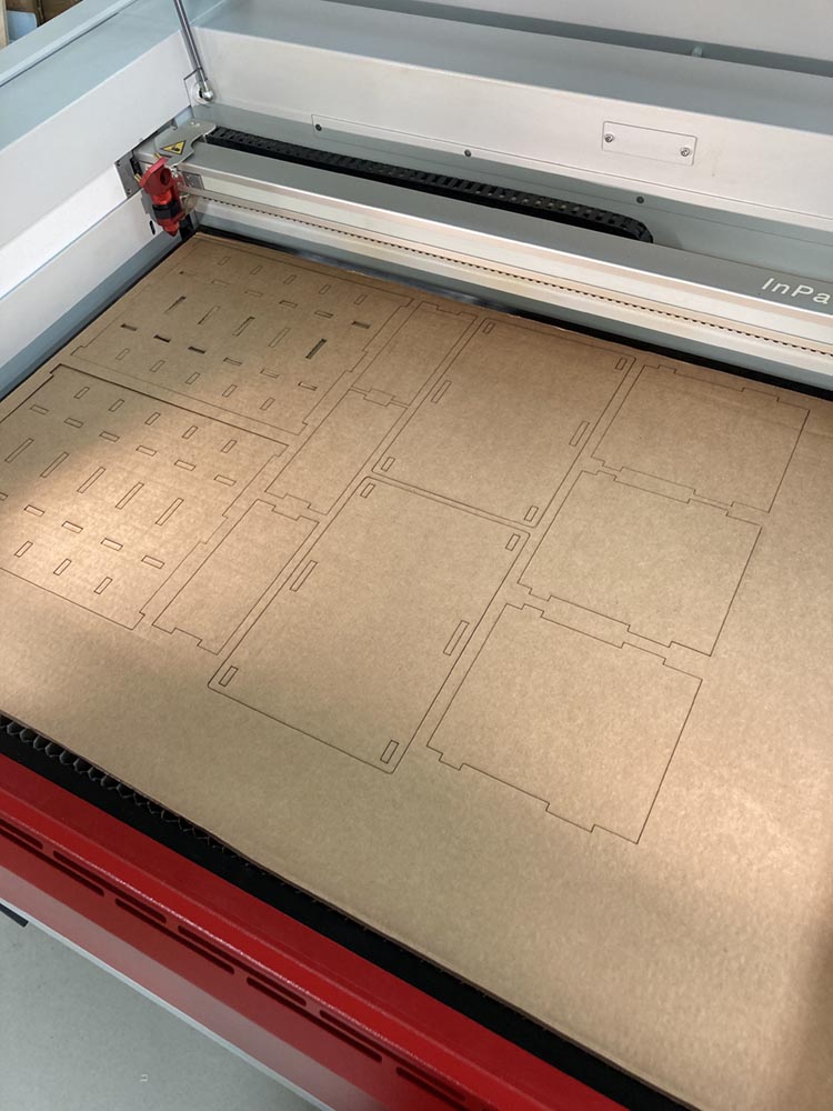
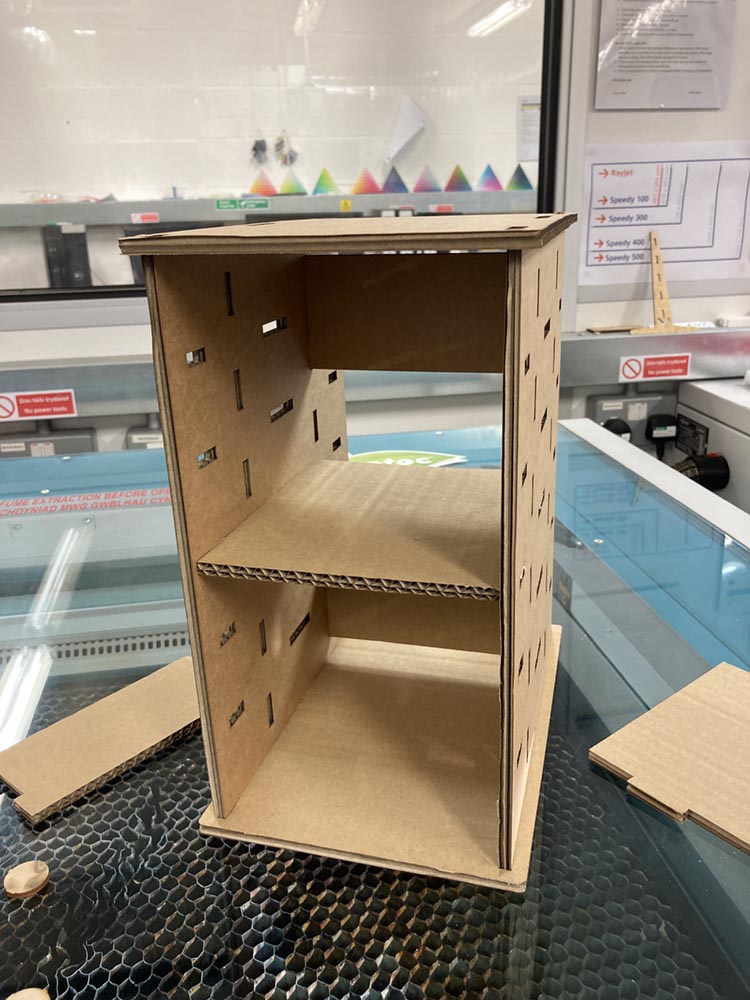
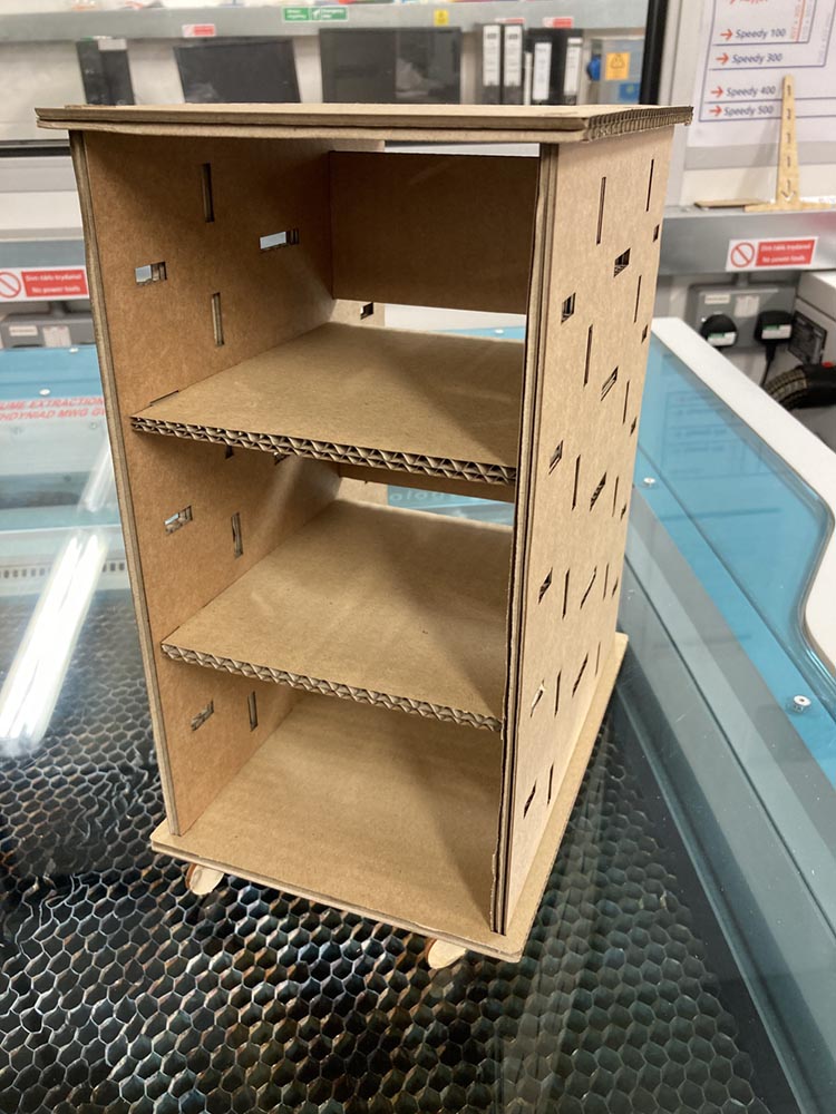
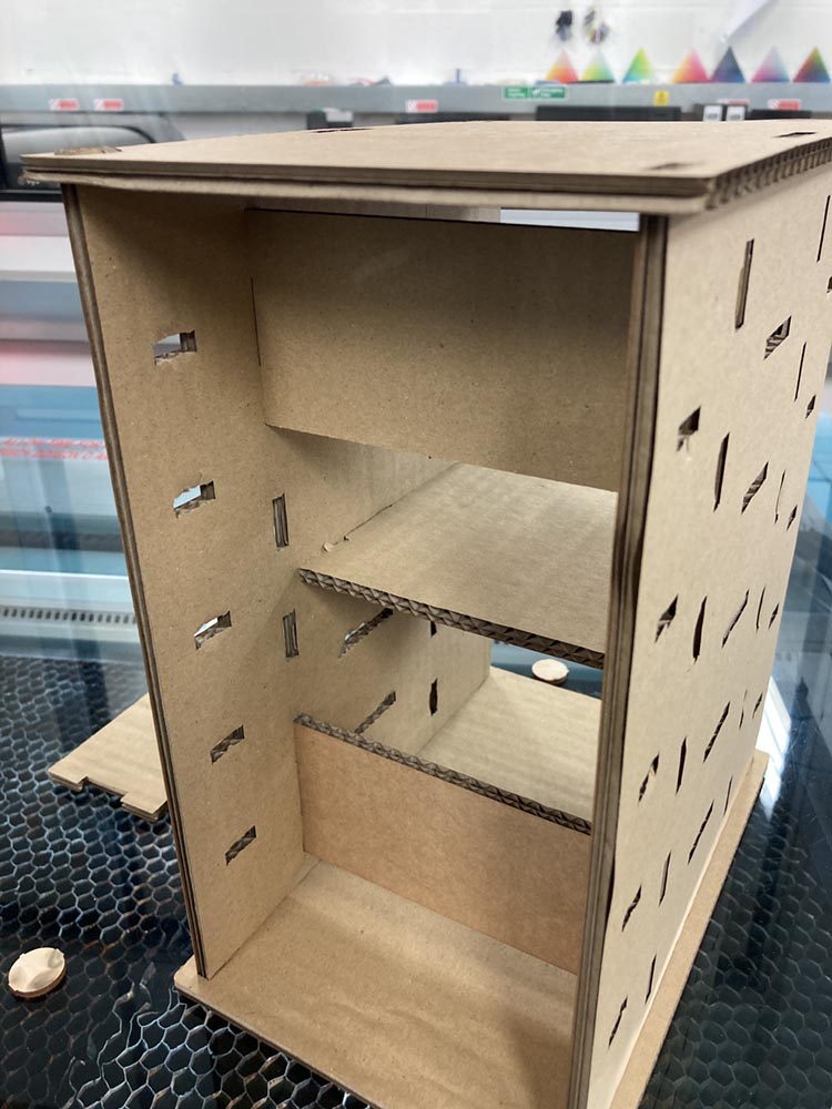
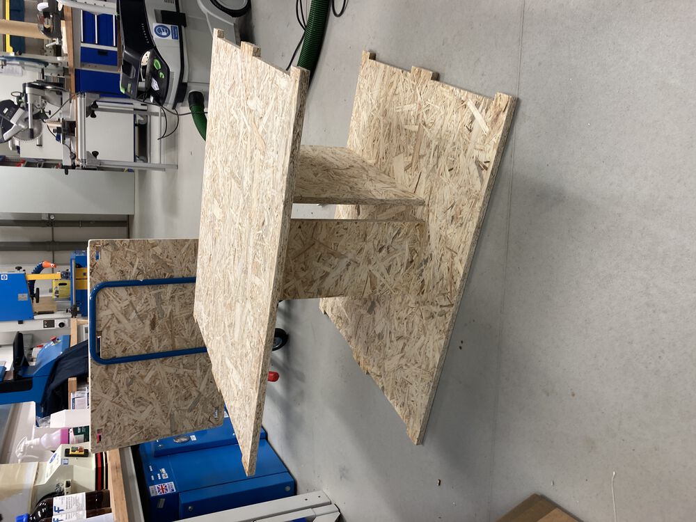
Scale Prototype
To test out the design we did a 1/3 scale model in card.
 Showing a couple of configurations
Manufacturing
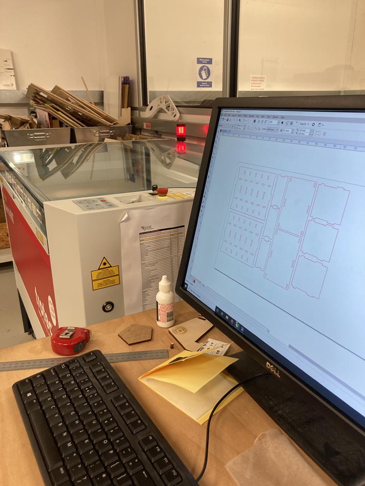
Having designed the big thing in FreeCAD I discovered that FreeCAD did not have a post processor for our big machine, which uses a Fanuc controller. So below is a second attempt at designing the something big
Hero shot
Let’s get the Hero shot out of the way…
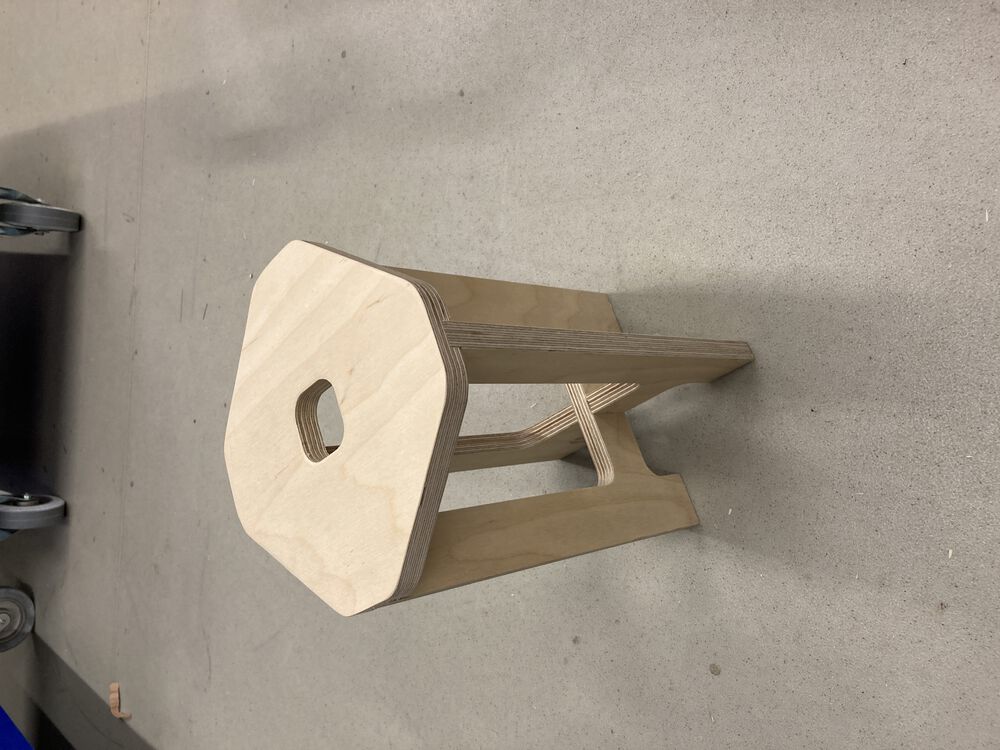
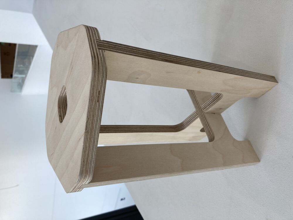
And a small stool that I used to test moving files from FreeCAD to Fusion for CAM, with .step files as my intermediary format, more details below.
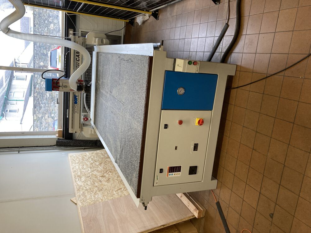
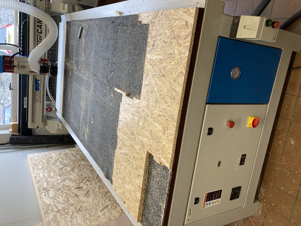
The real hero of our week… the big machine that does the work. (Excel CNC HD1224, re-badged and installed by Techsoft).
Small test piece
I decided to see if we could import something from FreeCAD into Fusion to do the CAM. Creating a simple stool and exporting the parts as .step files. The import to Fusion went ok. But my bright idea of using exposed pockets made creating tool paths a challenge. I also learned a…
Valuable lesson on Roughing vs Finishing operations
Creating the pockets with a pocketing operation defaults to being a roughing operation. So there is a default ‘Stock to Leave’ checkbox set. So if you plan to do pockets in a single operation be aware. I’ve gone into more detail on machining for the larger project below. Here we see the too small pockets. The leg parts were adjusted with hand tools to fit.
Remaking the model and CAM
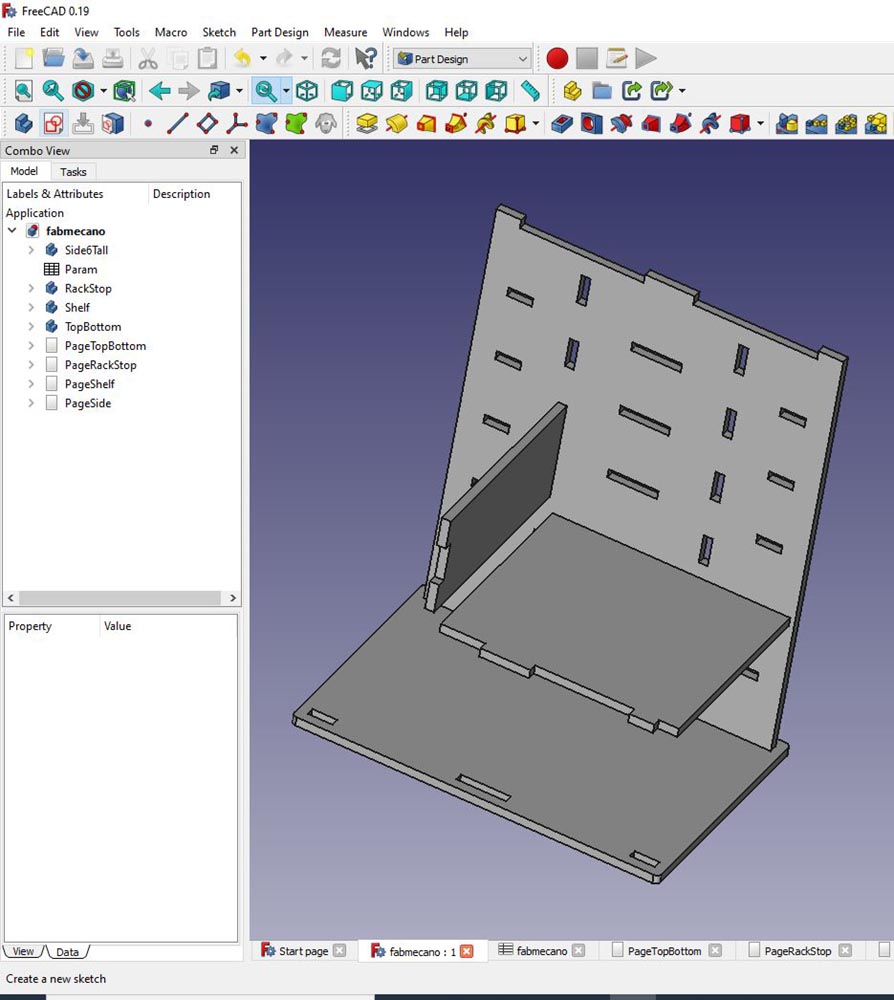
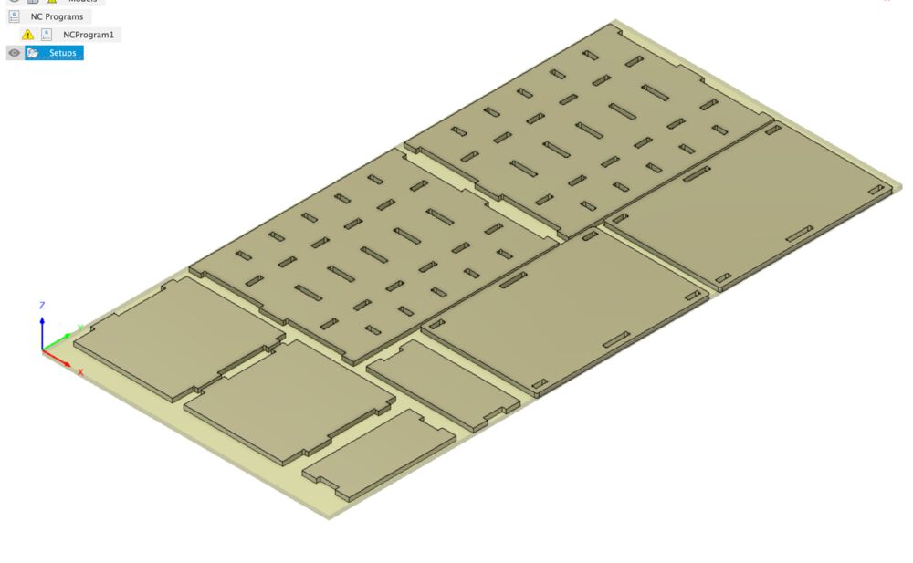
Back to the main event here we see an assembly of the parts for a piece of flexible Fab Furniture, as described in the design section a meccano for supporting the common small fab machines. A single piece uses one full sheet of material with little waste.
New bits of Fusion
I have done the very basics in Fusion, defined a sketch, given it thickness etc. but for the meccano I used a few techniques that were new to me in Fusion, having started my 3D journey in FreeCAD.
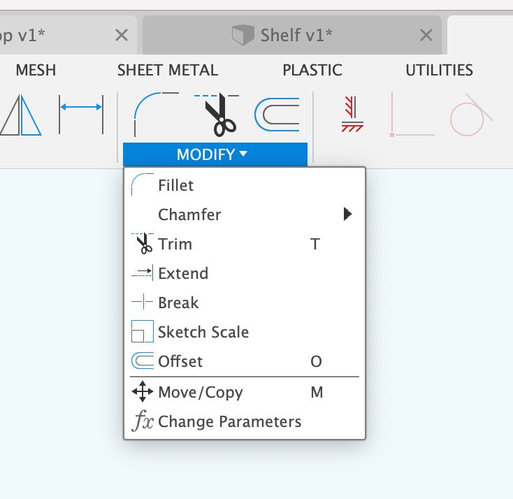
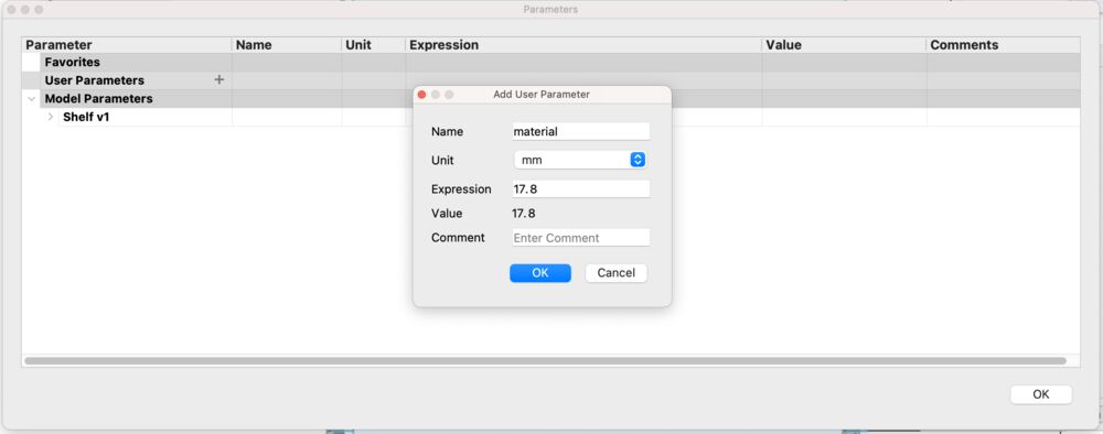
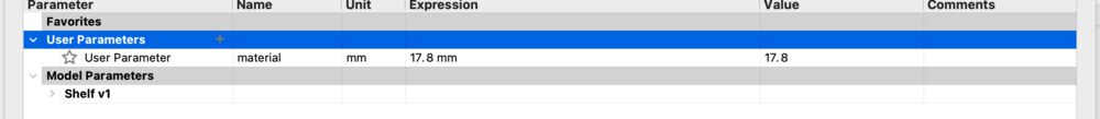
First, finding parametric design, under the ‘Modify’ menu dropdown find ‘Change Parameters’. There you have the option to add ‘User Parameters’. I designed all the parts individually before bringing them in to a single assembly file. The material thickness parameter had to be set up in them all separately.
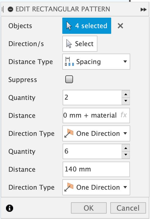
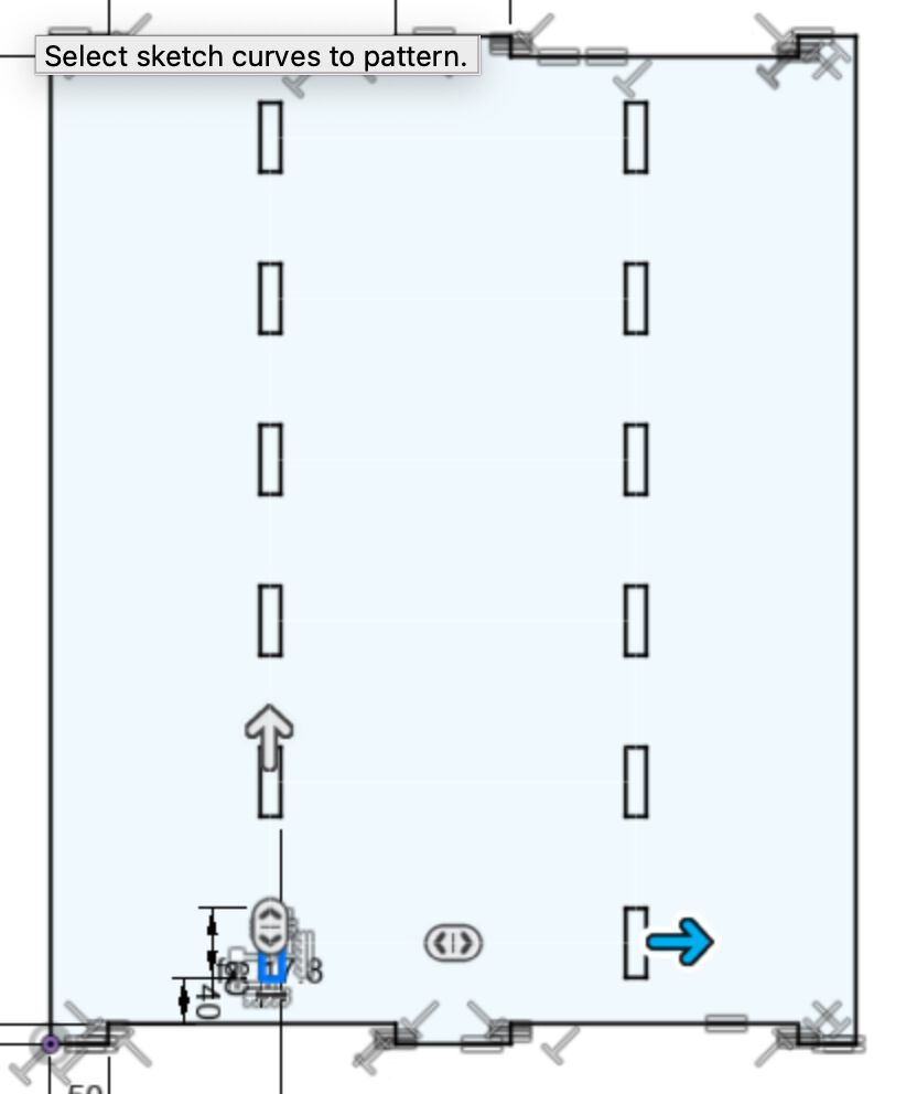
The next new thing to learn. In FreeCAD I’d laboriously defined the position of all slots in the large sides of the model. In Fusion I found and used the ‘Rectangular Pattern’ dialog under the ‘Create’ menu.
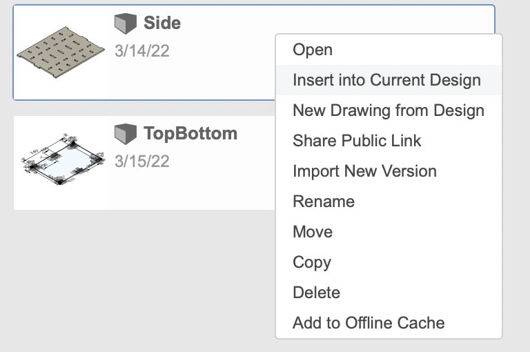
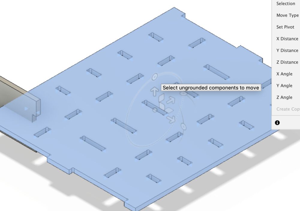
Assemblies are also new to me in Fusion 360. First step is to start a new empty file, then to right click on your source files in the data panel and ‘insert into the current design’. These items will be placed in their original orientation. for the example here we want to assemble the furniture to test fit all the parts. So we also need to rotate and place them in relationship to each other.
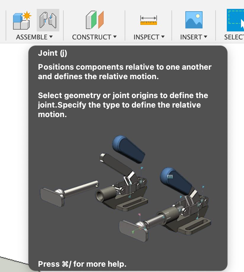
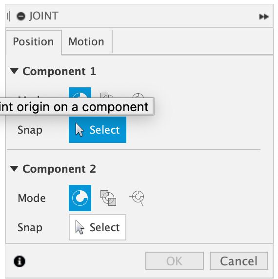
I found that the orientation of the individual parts stuck when we tried to mate them with a joint. The solution was to go into the original files and add a Joint Origin to the part.
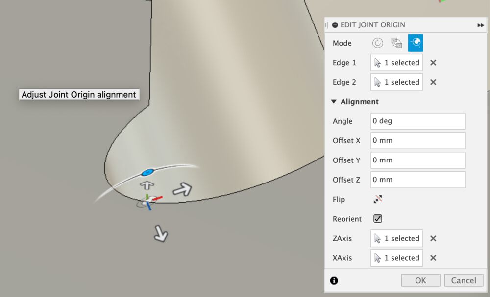
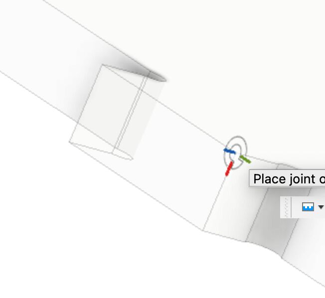

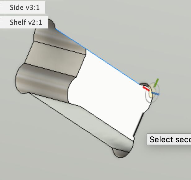
When both mating parts had a joint origin, going back the the assembly and making the joint using those markers worked fine.
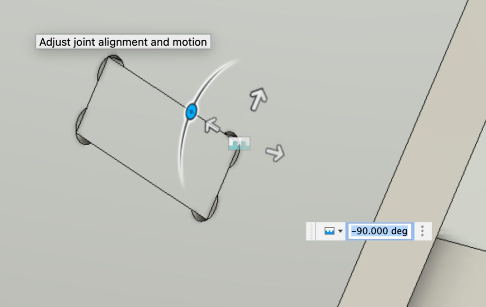
A finished assembly.
Dog Bone
I tried a free trial of the Nifty Dogbone addon for Fusion 360.
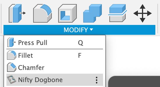
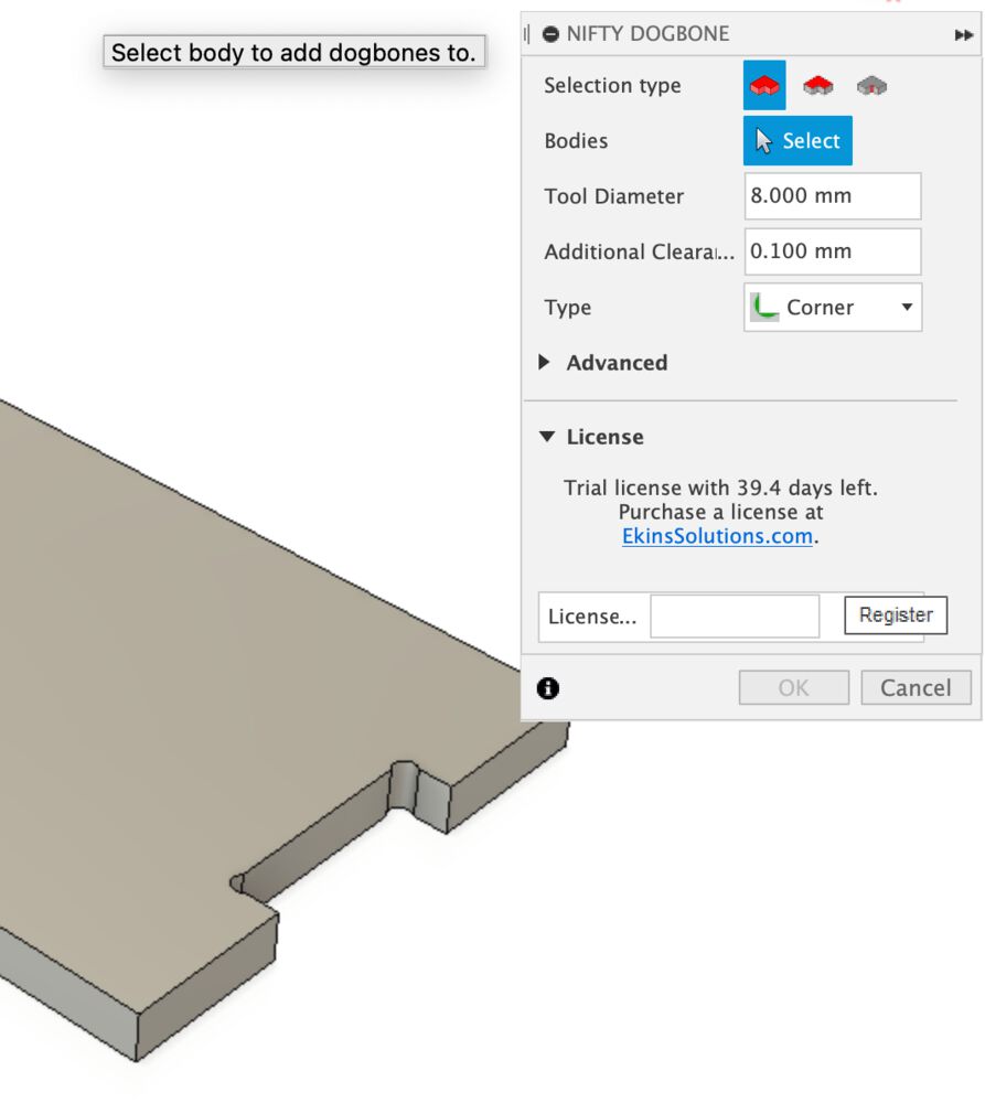
Once installed it appears under the ‘Modify’ menu. It could not be simpler to use. Point it at a body, tell it your tool diameter, give it a bit of leeway and away we go.
Tool paths and Post
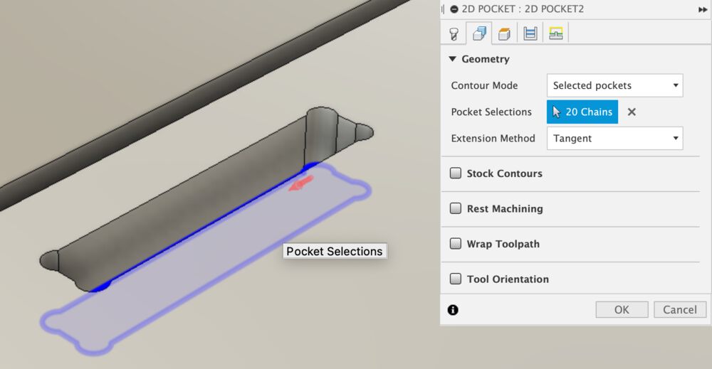
We need a couple of types of operations for these parts a contour for the outside, and pockets for the inside.
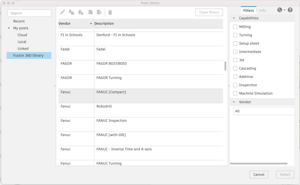
First page of a new operation asks you to setup the tool, we picked a 6mm End mill from the library
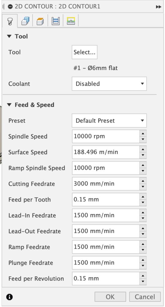
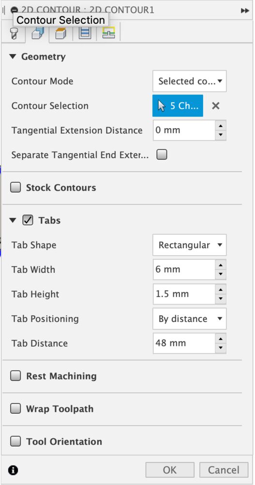
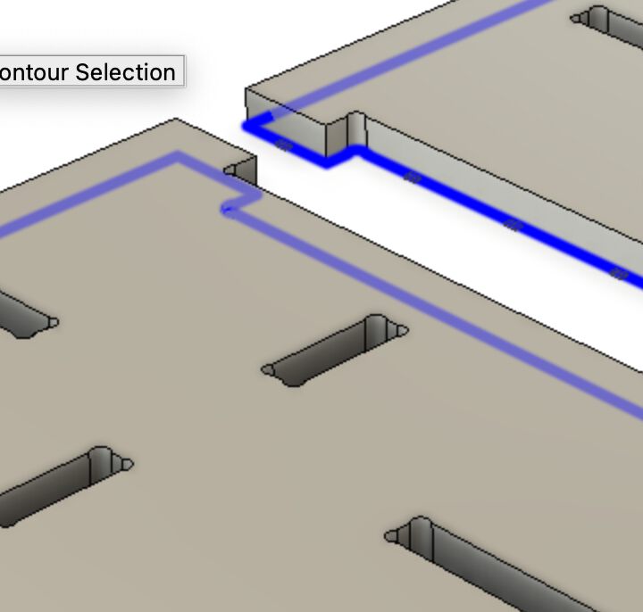
Contour selection tells the tool what you want to cut, notice that we selected the contour at the bottom of the cut, here we also set up our tabs
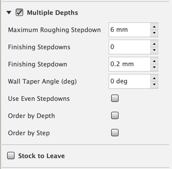
We control the depth of cut so that ‘Bottom Height’ is 0.3mm below the stock material, making sure that we cut through.
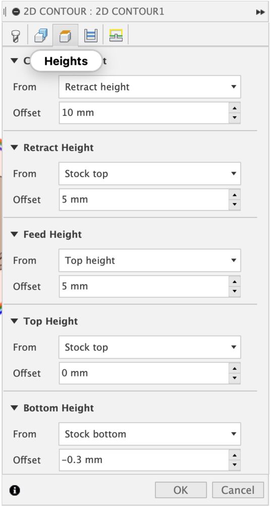
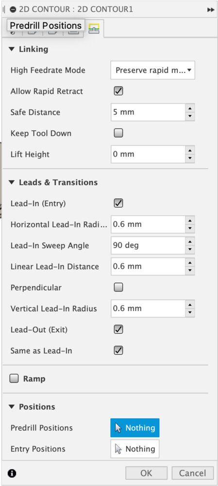
We want to use multiple passes with our 6mm tool into 18mm stock. As a rule of thumb don’t plunge deeper than the diameter of your tool. Here we also check on ‘Stock to Leave’ here switched off. On the last page of the dialog you’ll likely need to check on safe distance, making sure int interacts well with yur retract heights.
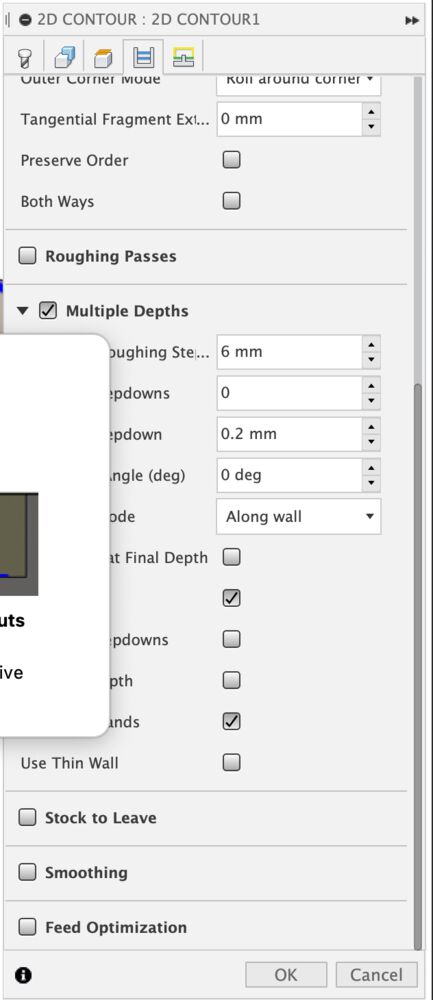
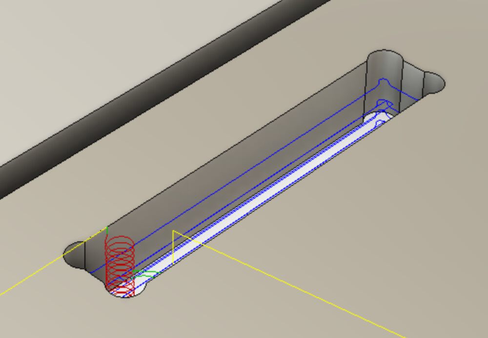
Setting up a pocket is much the same, again a bottom contour selected. Remembering here that it is a roughing process so Stock to Leave will default to on, we want to make these in a single operation so that’s been unchecked. The final path looks good, notice the ramping spiral down into the material.
A right click on out operations offers the ‘Simulate’ and ‘Post Process’ options.
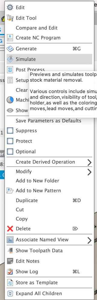
Always simulate before you go to generate code
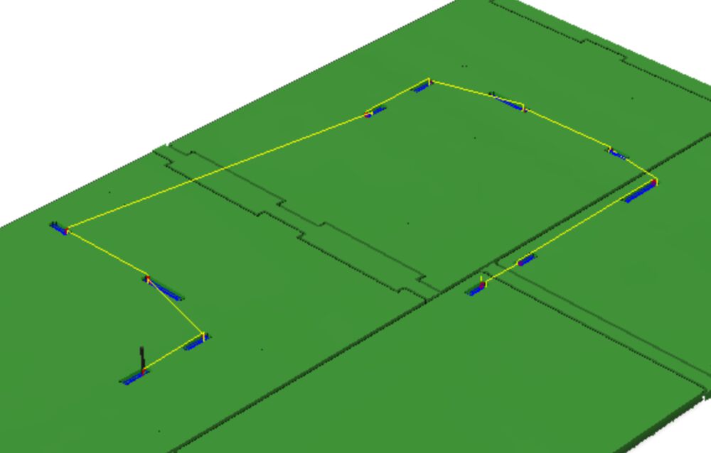
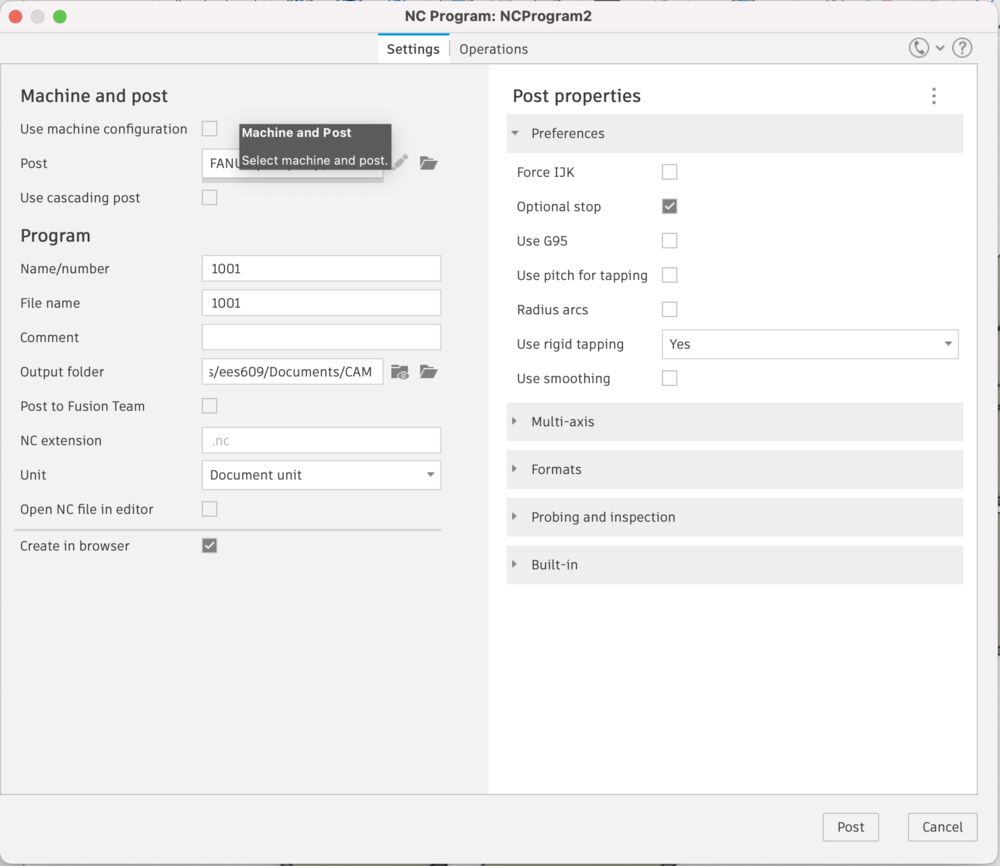
Start with selecting the right machine to produce g-code for
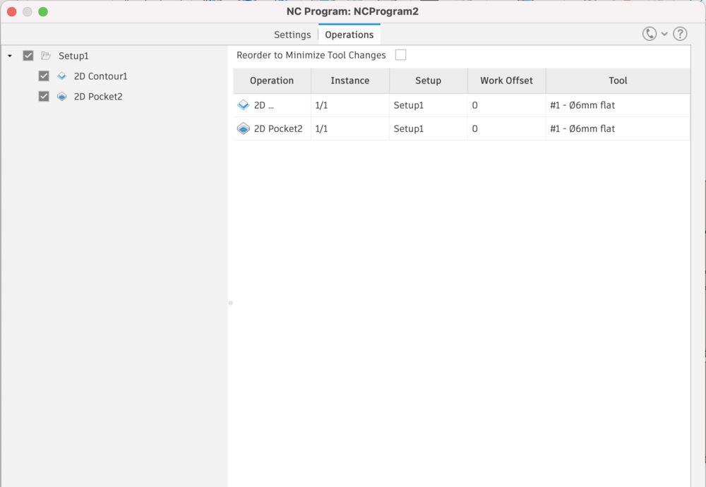
Make sure you have the operations you want to output in this piece of code. We have no tool changer, so if there were multiple tools used I might consider splitting out the operations to more files.
Make sure you know where your file is going to
With the g-code in hand we can go and do some manufacturing
Machining
For my solo equivalent of Group Work I thought I should document the safety features of our own machine.
Safety
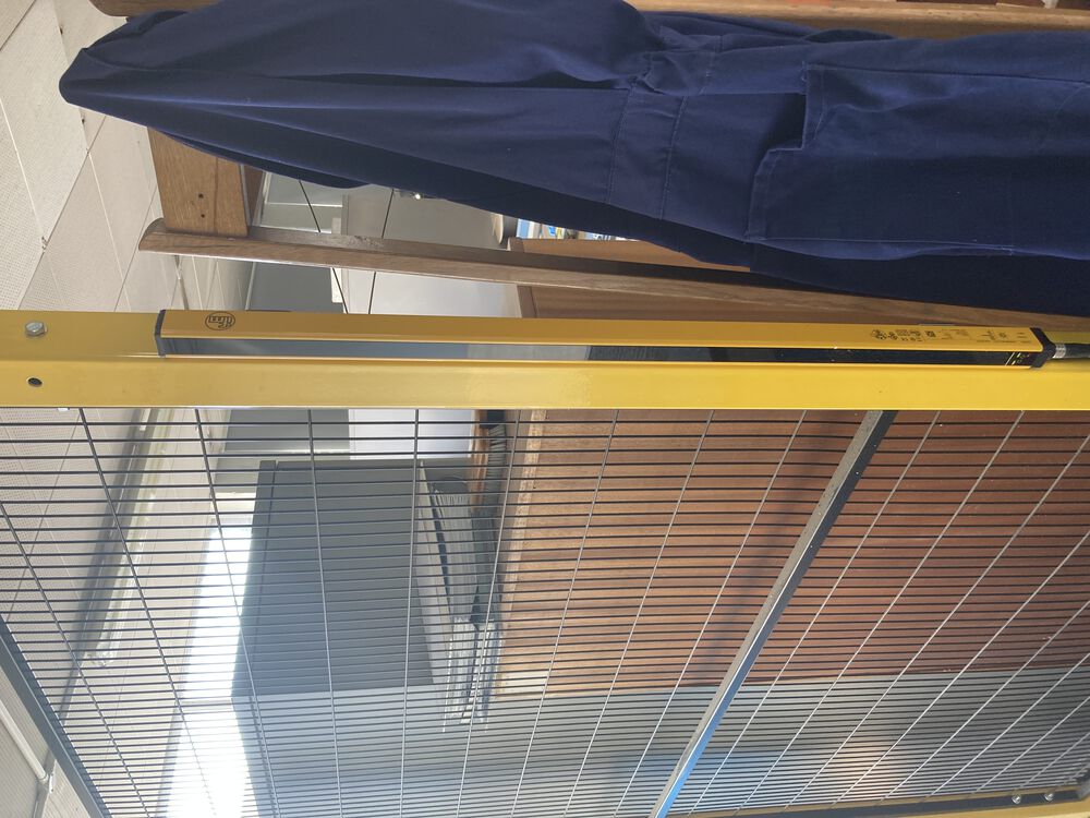
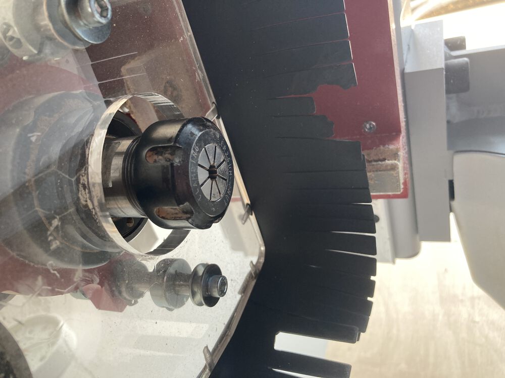
The Router sits in a caged work cell with a single open side protected by light curtain.
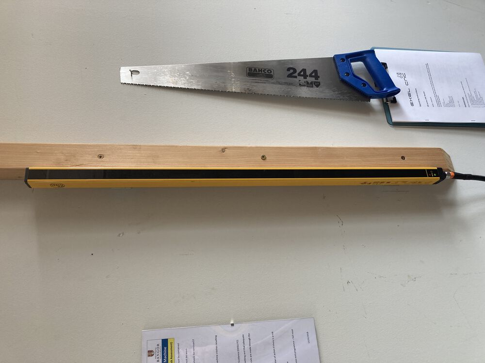
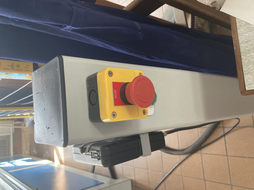
The control pendant in on the outside of the cell mounted to a pillar with an easy to get to stop. If the machine is being driven by a program anyone interrupting the light curtain will stop the machine. This usually happens when someone remembers that they didn’t turn on the vac bed which is the only regular control on the inside of the work cell. A stop like this is not recoverable, you need to reset Z0, and restart the milling job.

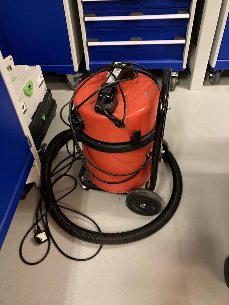
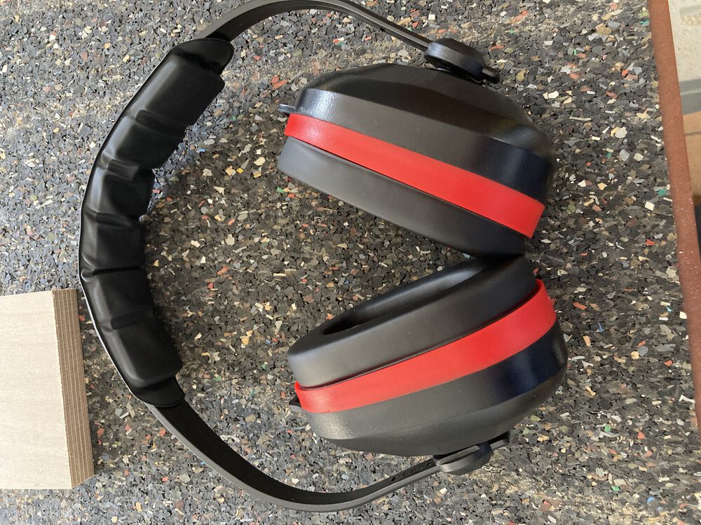
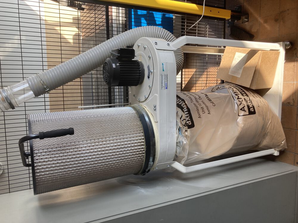
Ear defenders and eye protection are used and suitable extraction. We’ve upgraded the extractor since this image was taken, installing a similar machine with double the horsepower. A recent survey suggested that the old extract was borderline for the scale of the router.
Another safety principle here is regular review of safety, making sure we are up to date with best practice as it evolves.
Speeds feeds and runout.
We set speed and feeds according to material and tool. Generally a manufacturer of a tool will supply chip loading data that allows your CAM tools to calculate speeds according to number of flutes as a main factor.
As a rule of thumb in timber like products we’re running feeds at 4000mm/minute.
I didn’t have time to mill a specific test for run-outs, but would say that the design for my something big used a parametric thickness for stock material in all joints and the results were push fit. We assume that runout is negligible. The frame of the machine is made from 4” welded box section, it’s a very rigid machine, well set up, I assume that alignment is sufficient for most of the tasks that we’ll attempt on the machine.
Work holding
Our machine is fitted with a vacuum bed. A porous rubber material is laid on a gridded bed. The channels in the bed allow us to make a seal custom to the current work piece.
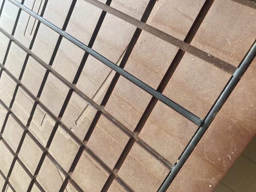
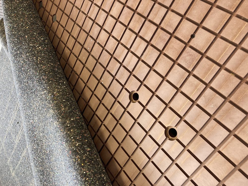
The grid has a number of ports plumbed into the vacuum pump. To prevent the pump from overheating it’s important that one or more of the ports outside your workpiece are open, allowing some air through the system.
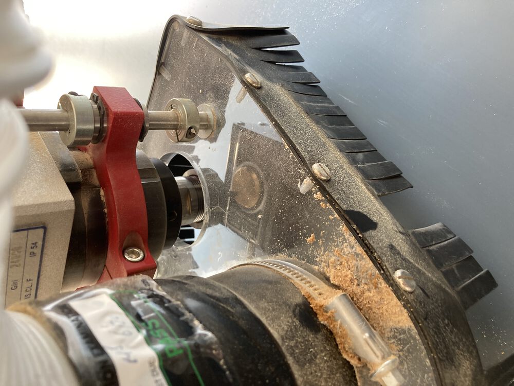
Tool changing and setting Z.
The correct spanners applied above and below the dust shoe allow us to change a tool.
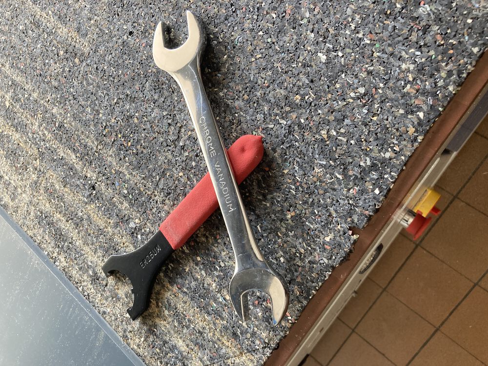
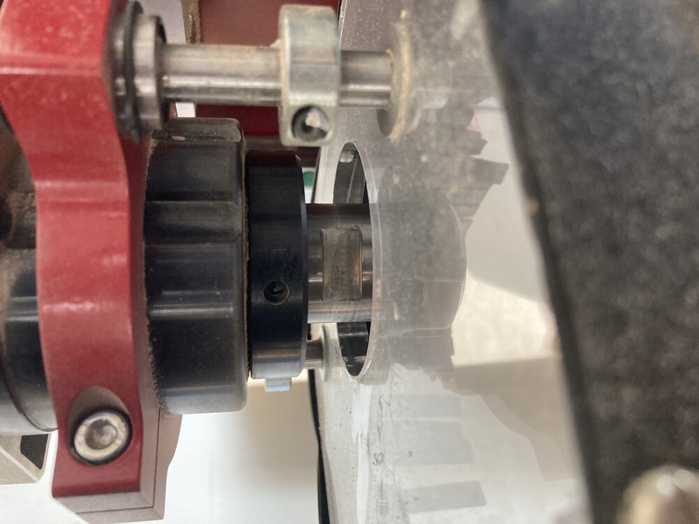
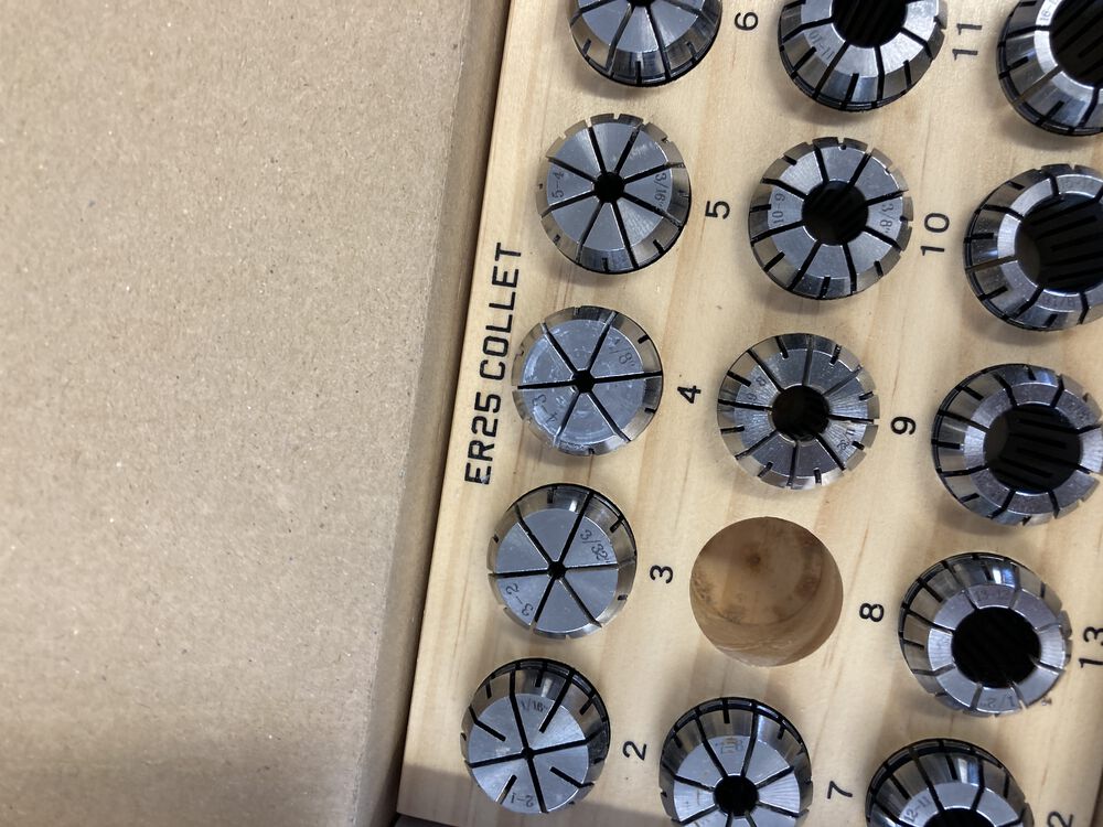
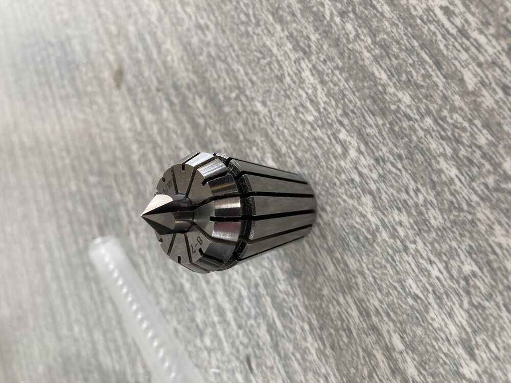
Note that one spanner is toothed to mate with the collet nut. We have a range of collets available to suit different tool shanks. Once the tool is in place the next step is to zero the Z axis.
With our setup it’s very important to make sure that the vac bed is switched on before setting the Z0. The vacuum is strong enough to pull down your work piece, depressing the rubber material. This can make a significant difference if you are milling accurate cuts in depth.
The Z0 is set with a sensing puck placed under the tool and the Zeroing routine set going using the pendant. The collet is electrically wired for this process so there is no additional crocodile clip for the tool.
For a compete rundown see the Week 8 Group Assignment
How it went…
One mistake was made but it went quite well overall.
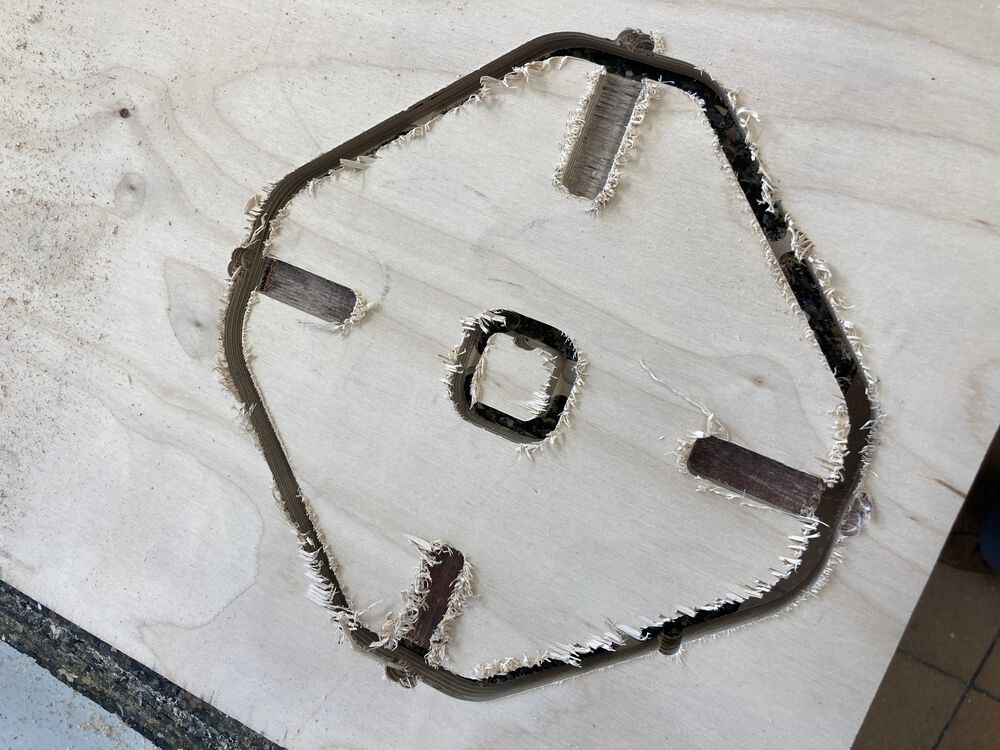
At the far end of the machine I didn’t spend enough time checking that my material was square on the bed. The job takes up the whole sheet with little margin for error across the material. With the misalignment that I had I lost about 4mm from one corner of one piece of furniture side. The connections in the carcass are sufficiently redundant that it didn’t impact the final piece beyond a cosmetic gap.
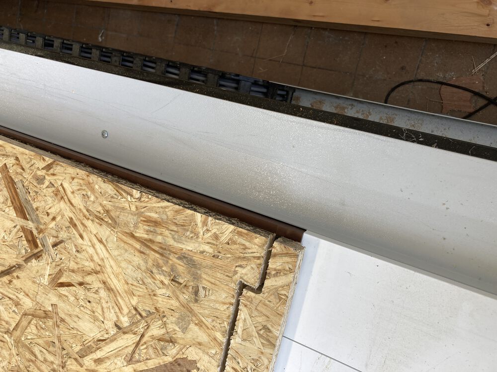
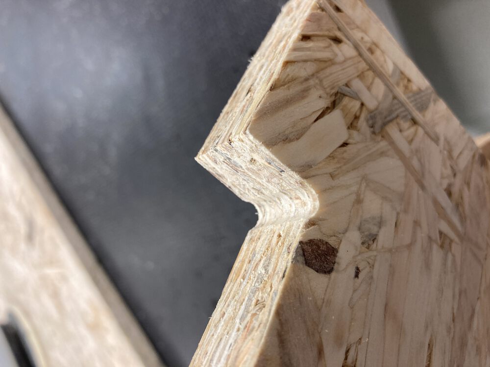
Using OSB I and a regular up cutting fluted tool I was expecting some tear-out, it sanded out fine:
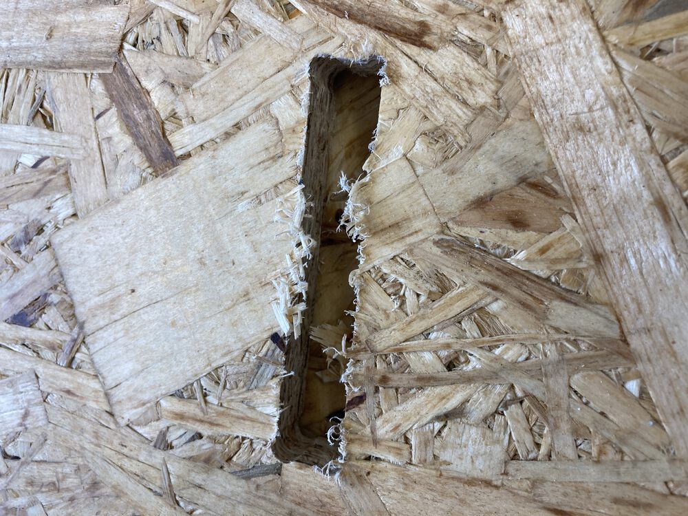
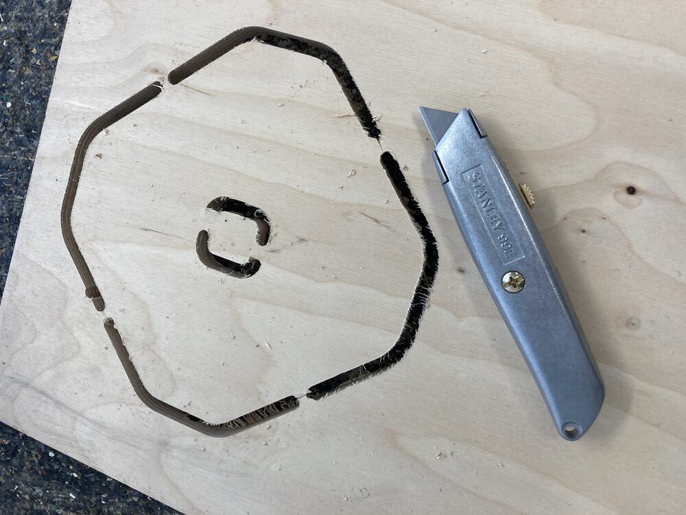
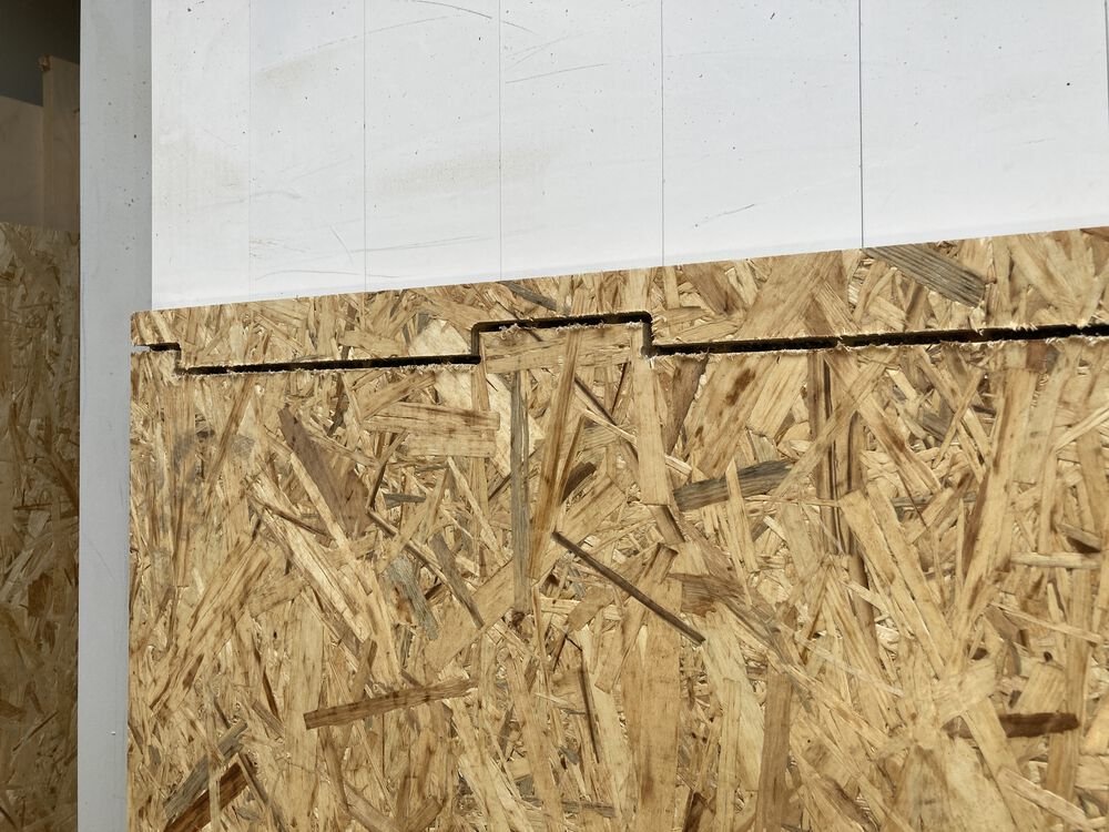
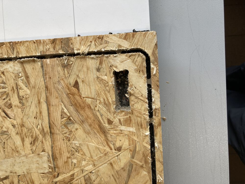
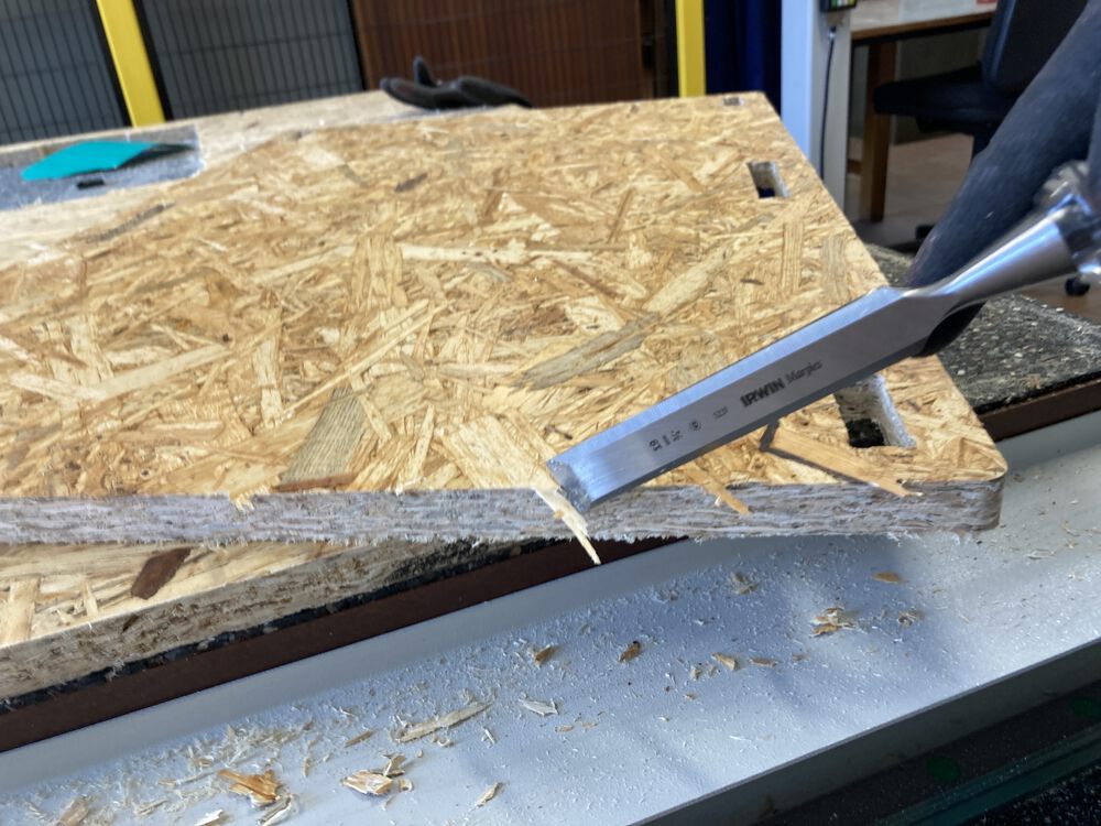
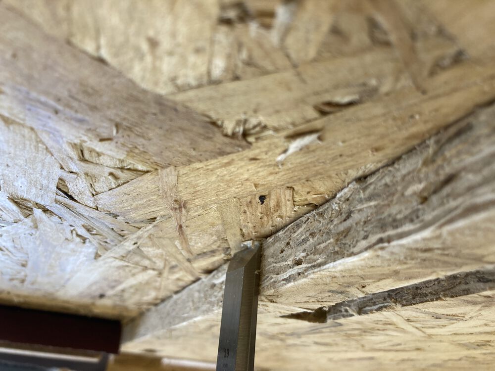
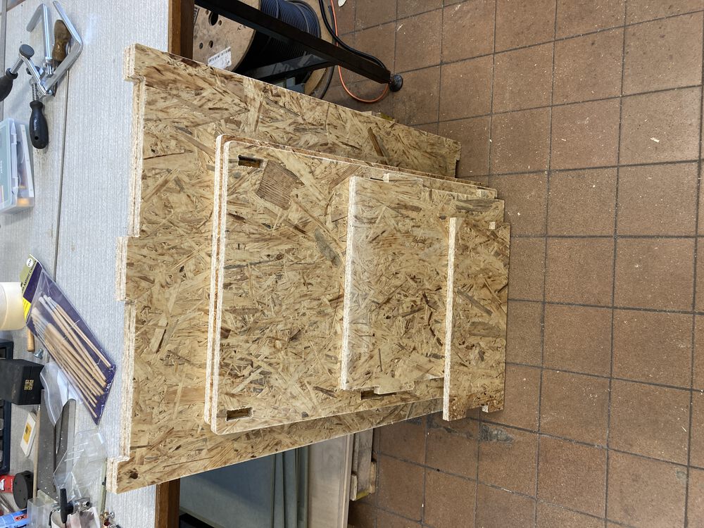
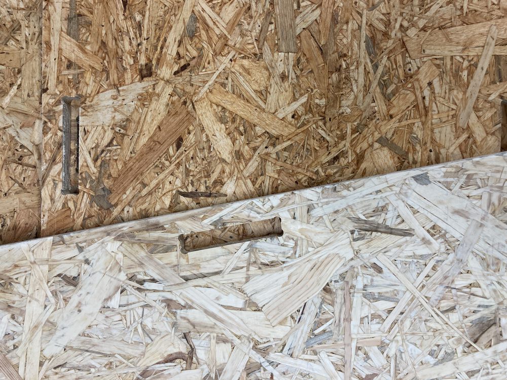
Removing the work from the machine we can see that the tabs held the material together sufficiently for holding down material. They snapped with enough pressure for removal. Clean-up was done with a sharp chisel. For most tabs a sharp push along the edge removed them. For some with a stiffer bit of material embedded the workpiece was put back down for a firm whack against a backing.
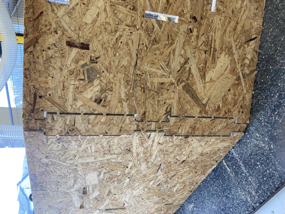
There was very little waste from this design. We did some of the machining in stages to gradually prove out our process.
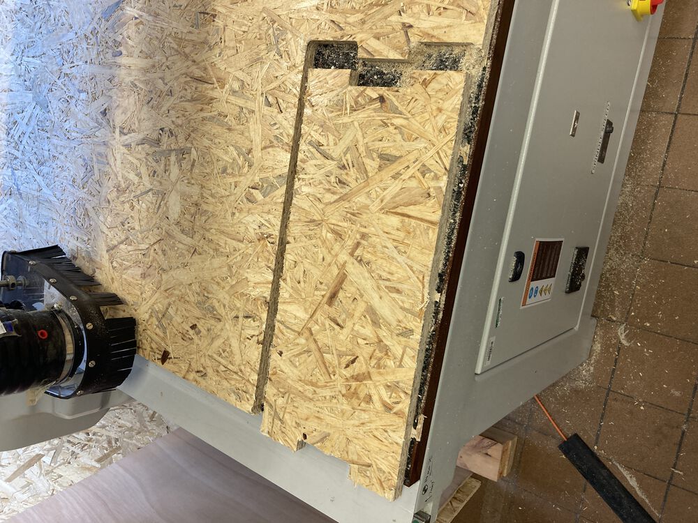
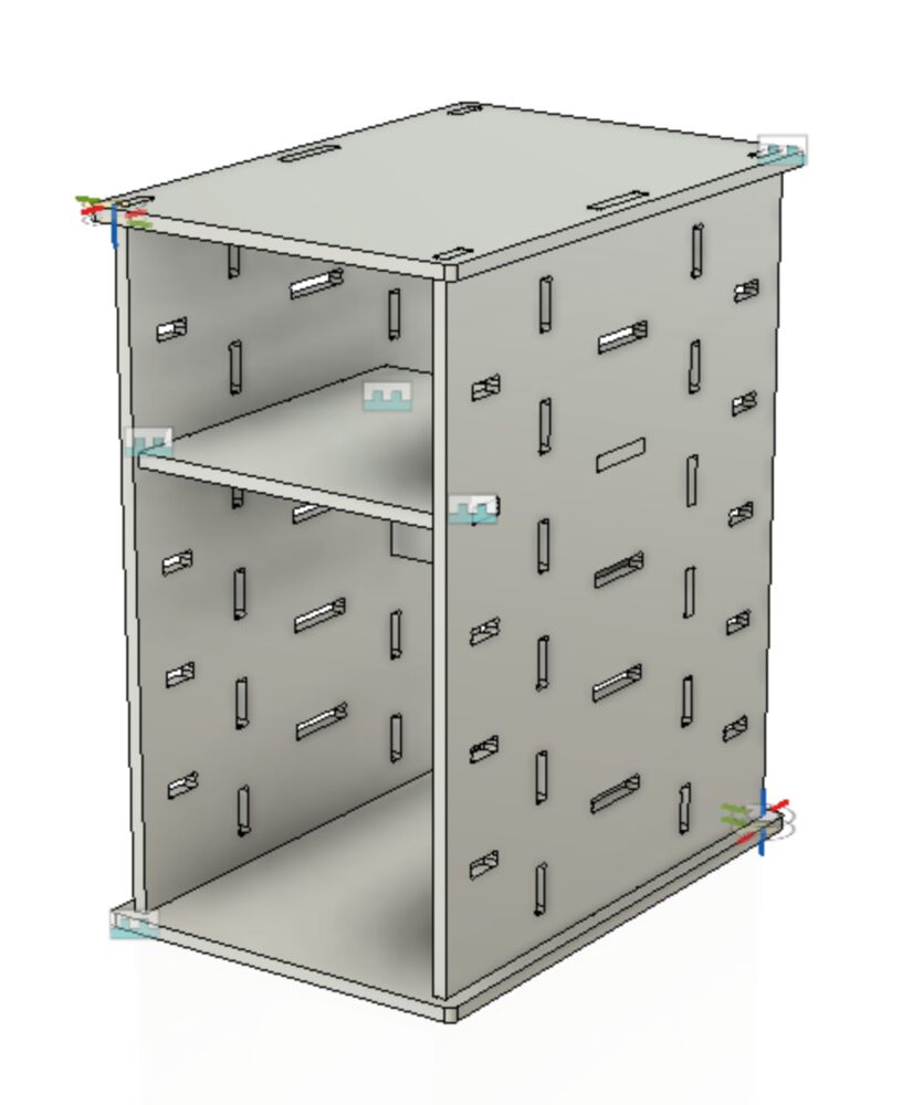
We ended up with sides, top and bottom, shelf and rack-stop (inside back).
Assembly
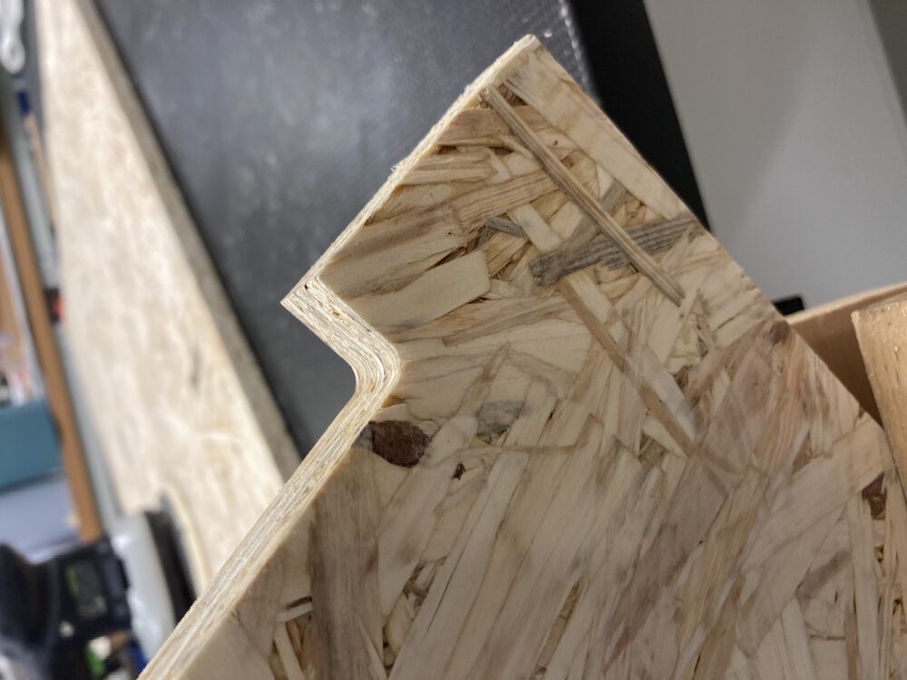
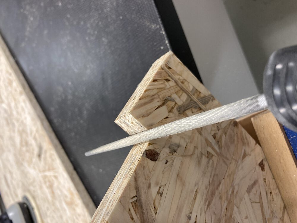
I did end up machining my first part without dog-bones by mistake, this was simply fixed. I think it’s important that you have some basic skills with hand tools if you are to make best use of any workshop.
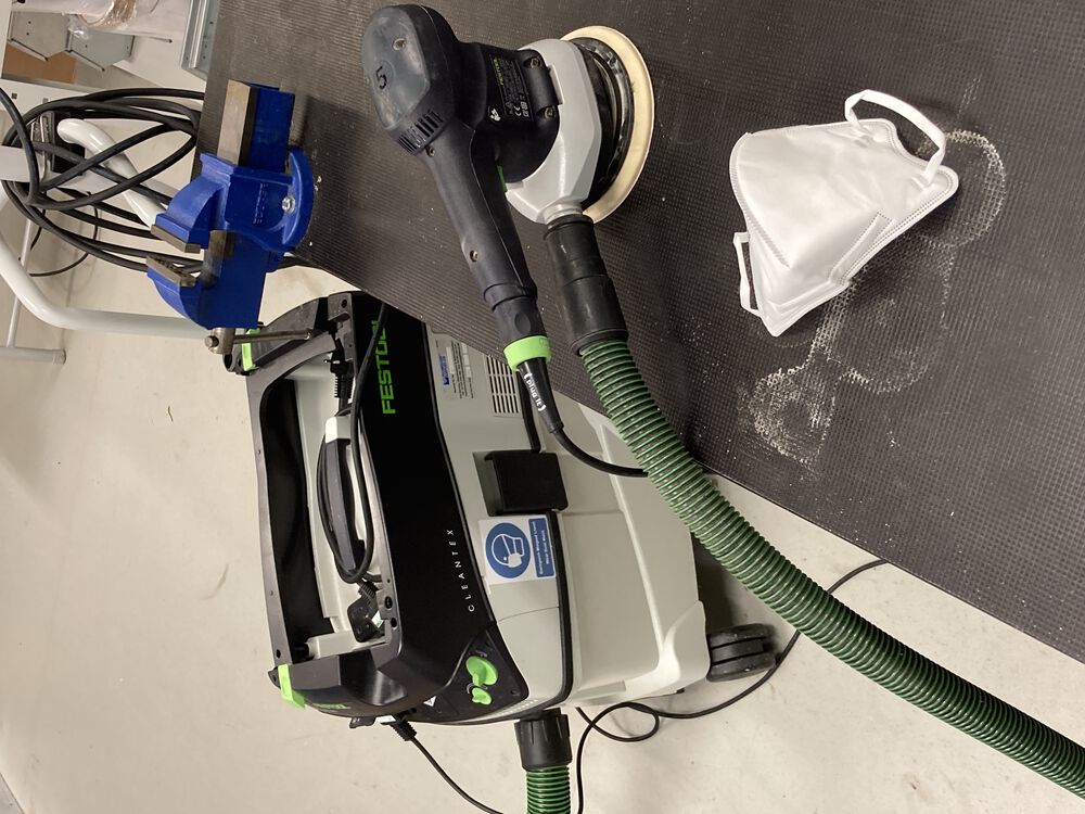
Basic finishing was done with an orbital sander, working from 80 to 320 grit. We use a vac system here for safety as well as a FFP2 mask for backup. Pushing the parts up against a bench dog stops them from skating around the bench.
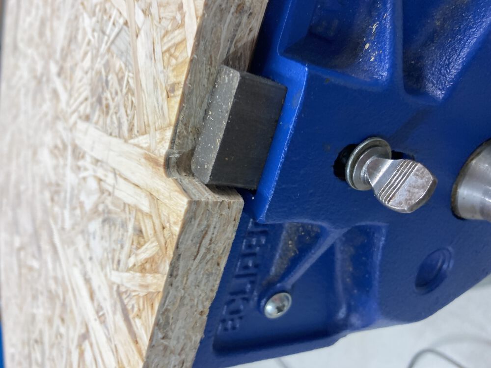
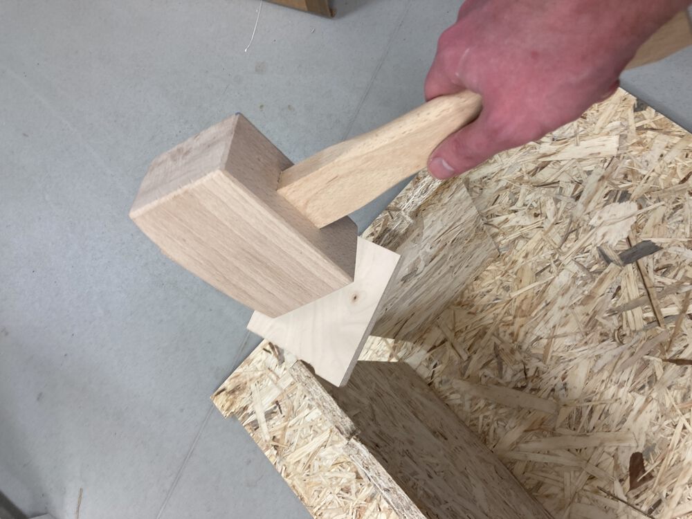
We used a scrap of wood and a mallet to mate all the parts.
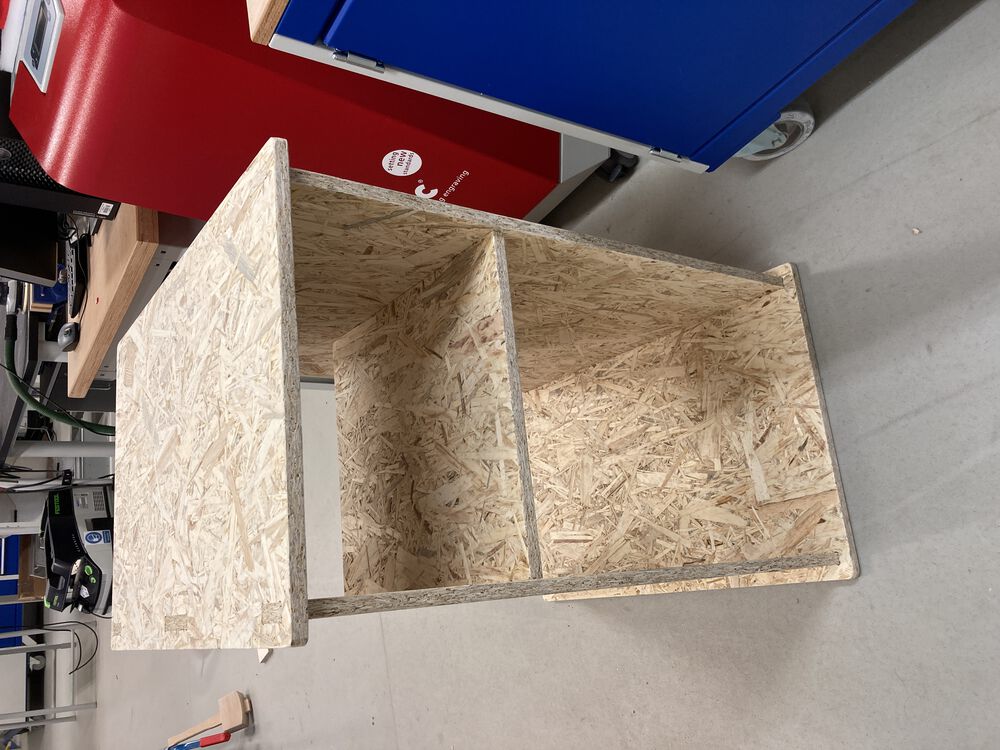
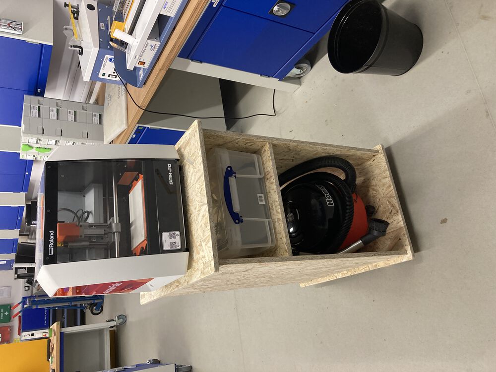
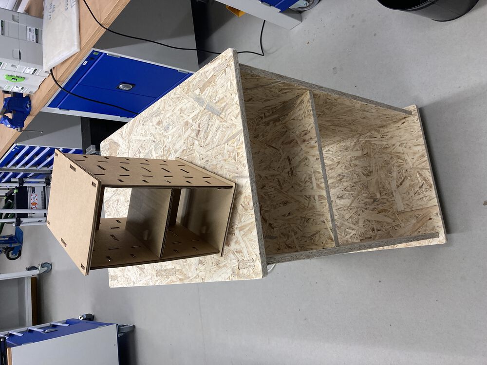
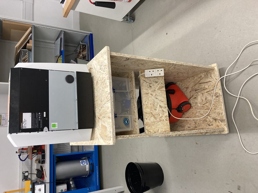
The assembled piece with the scale model for reference and then testing is out with the SRM-20 + extract + storage, where everything fit as designed.
Last thoughts
At the moment it is sat up on blocks, we need some castors to finish the piece completely. I would like to possibly route some ducting for the extract with a splitter to provide a second hose for vacuuming out the cabinet of anything the fixed extract misses. There is some racking, it’s not quite stiff enough with a single back piece in place, I think a next revision will put in a brace at the top and bottom available slots.