Computer Controlled machining: Week 8
Introduction
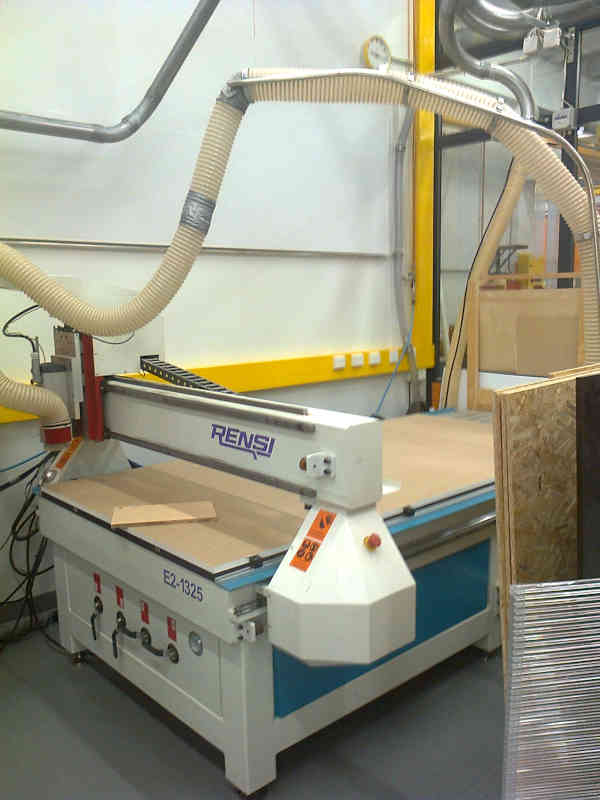
This week we learnt to use the CNC machine in our Lab ("Rensi" E2-1325) and revised the general safety practices.
The group assignment is 1) to do your lab's safety training and 2) test runout, alignment, fixturing, speeds, feeds, materials, and toolpaths for your machine
General safety practices
As part of a safe practice we used protective goggles and ear protection. The location of the protective gear was shown to us.
We were also told hot to pause the milling and how to use the emergency stop for the machine. The emergency stop loses the current progress on the milling, while pausing doesn't do that. We were also told that the bits are quite sharp. Neil told us at the global lectures that using too high speeds may cause fire.
We are not allower to use the machine alone and when we do the individual part of the week, we should do it with the instructor.
Introduction to the task
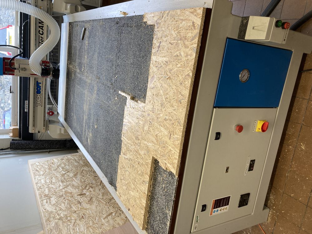
E2-1325 is a milling machine manufactured by Excitech. It was sold by Rensi Oy in Finland. It originally has a working size of 24801230180/280mm, but the instruction we got mentioned table size of ~1,2 m x 3 m.
We were given a model created by the instructor. We mill the model with the help of the instructor.
The design file for the model is available here.
Materials
This time we were going to use 14.mm plywood. The bit was a leftover from a previous project. The material we are going to use in the individual project looked more coarse, consisting of glued bits of larger chunks of wood and it obviously is of a lot lower quality. We were given instructions to ask from Jani, if we needed more expensive materials in our final project.
Set up
We first turned on the main power supply, which is located at the bottom of the cabinet with the computer. Then we powered the computer and the display. As the last thing in the sequence we turned on the machine by using the green button above. It literally says power on.
The program we use to controll the machine is NcStudio. With which we placed the tool in a comfortable position for us to replace it.
We started the NCStudio on resetted all axis. We returned all the axis to the home position, so the machine knows where the zero position is.
At the right side of the screen there were arrows for moving the head manually, for example, pressing X+ (to the right) and Y+ (away from the operator) buttons move the position of the head.
On the top left corner there are coordinate systems both for the machine coordinates and for the design coordinates.
File is imported from File -> Open document menu. There is an NC code window for checkin that the NC code is loaded.
Installing the milling bit
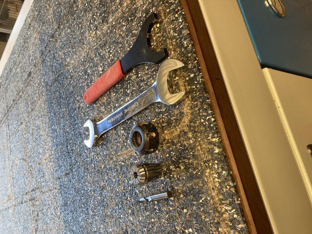
We remove the dust cleaner cover by removing two screws. We need twoo tools, a special tool and a 27 mm wrench to remove the tool. There are thre parts, collar, collect and a tool in the assembly.
We remove the collarfrom the collect and use compressed air to clean the assembly. We installed the 8mm milling bit and fastened the assembly back in its place in the toolhead. Then we placed the cover back and fastened the screws.
Fixturing
The material was originally placed on the nearer left quadrant of the milling board.
We needed to fasten the board. The fixturing was done by using the vacuum suctioining system. This part of the operation differs from the instructions given in the instructional video. There are two vacuum pumps installed in the board. The vacuum pumps suck through the material of the milling board. The second wacuum pump was a recent upgrade. It was installed only a few months ago.
There are four valves installed in the machine stand. Each of the valves operate a quater of their own of the board. We placed the stock in the table and turned on both the vacuum pumps to properly fix it in place. We put the board on the nearer left quadrant of the table and opened only the valve corresponding that square.
Alignment
We moved the location of the head to the good looking location by using the buttons. There was enough material for the job in the right directions, so the selected location was considered a good starting point for the job. Then we moved the mouse cursor to the Work Coordinates (W.Coord) and clicked the value. The NcStudio asked if we wanted to reset the value to zero.
Note that there is only an option to reset the value to the zero available. Now the X and Y coordinates were set correctly.
There were two options for setting the Z-coordinate. We chose to use the mobile calibration tool We placed the calibration tool on top of the stock right under the bit and using > Operation > Mobile Calibrator... the Z origin was precisely located. In order to avoid damaging the equipment, it was important that the mobile calibrator was set on the correct location before beginning the calibration program by pressing "Kyllä" in the pop-up menu.
Regarding the Z dimension, our design files were meant to use a 16mm plate, but our material was only 14.7mm, so we had to rise the origin 1.3mm from the material by using the NcStudio controls and then set that Z coordinate as new origin coordinate. Without this manual adjustment, the machine would cut 1.3mm inside the table and we don't want to do that.
Toolpaths
"The word “Toolpath” is a CAD/CAM related term that is basically a series of coordinate locations that a cutting tool will follow in the machining process."(2D Toolpath…Why You Need It.).
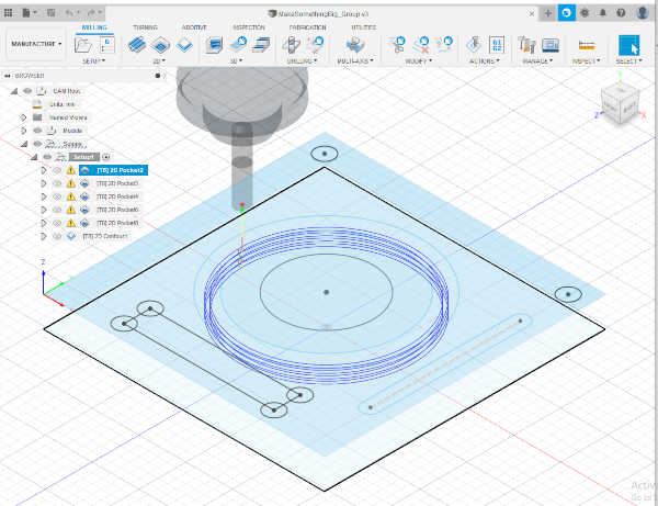
We simulated the toolpaths by pressing the smaller play-button in the menu.
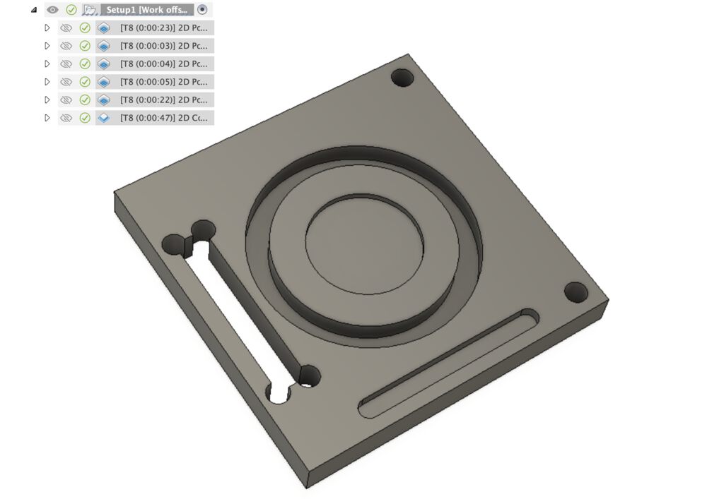
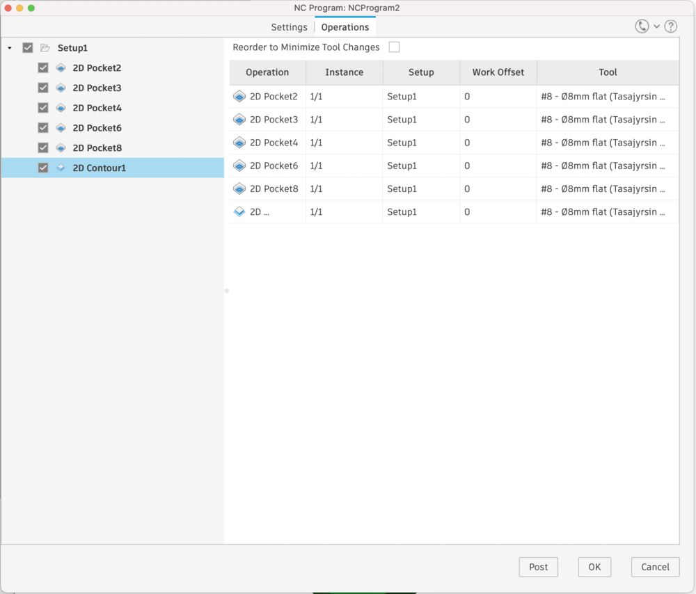
The toolpaths were defined in the Autodesk design file. They can be seen under Manufacture part.
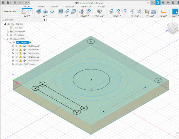
Example of one milling toolpath.
We tested the toolpaths by milling and comparing the achieved results to the intended results.
Milling
Starting the milling
Before starting the mill we turned the dust collector on. Next we pressed the play button and the machine started milling.
Speeds and feeds
"Speeds and feeds are the cutting variables used in every milling operation and vary for each tool based on cutter diameter, operation, material, etc."(Speeds and Feeds 101) We used a spindle speed of 18000 rpm, which we changed during the milling according to the instructions given by the instructor. We had to reduce the spindle speed every time it produced a high pitch sound. We mostly used an 80% setting. The feederate was of 250mm/min. The incorrect settings can lead to breaking the tool or burning it, so we were paying attention to the instructions.
Ending the mill
Pause would pause the machine during the milling. We used the protective gear.
At the last round, the mill made tabs. We needed to be careful that the workpiece was not removed from the workboard by the dill.
After the milling had stopped, the workpiece was cut off by using the knife. Cutting throught the board was ok.
The workpiece was removed (with suction off) and the sanding machine and a fillet were used to finish the details.
The computer and the machine were powered off, dust cleaner was turned off and the main power was turned off. We used compressed air to clean the table and cleaned the sawdust from the floor before leaving.
Most of the protective gear were also returned.
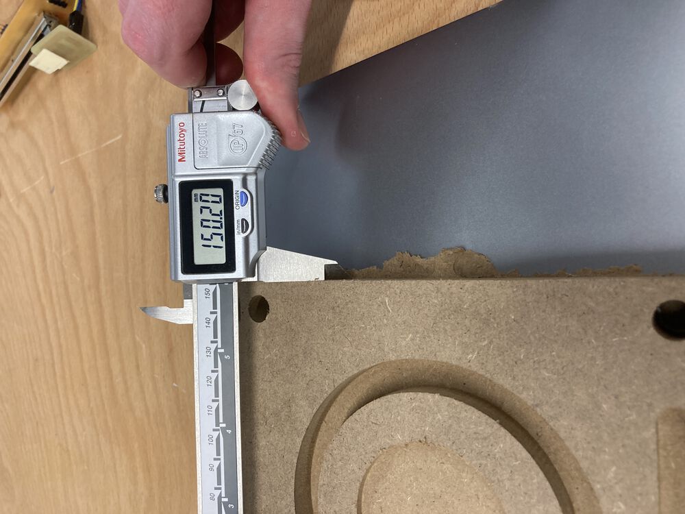
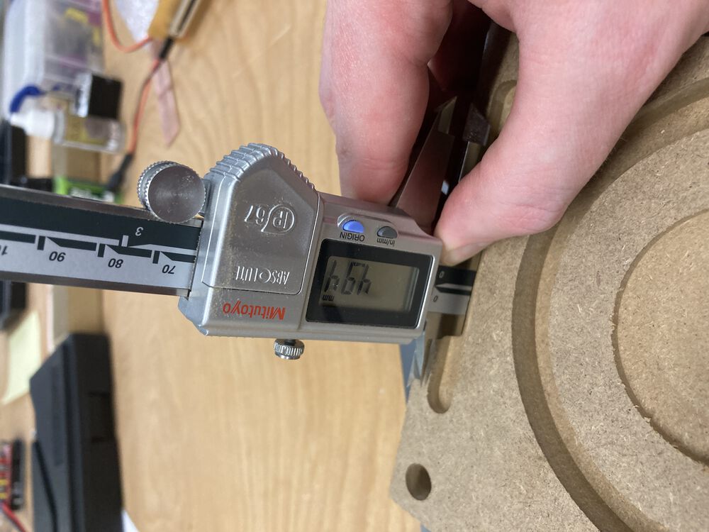
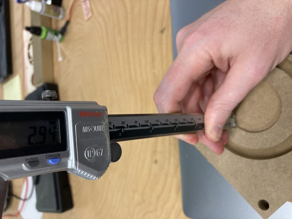
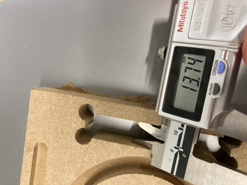
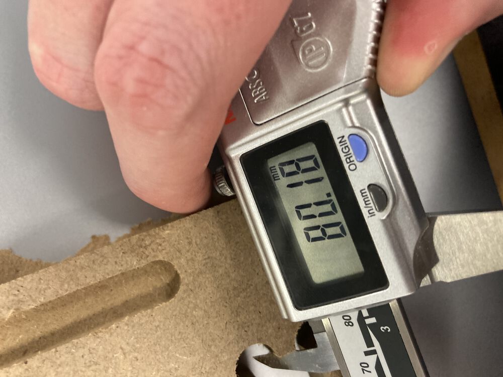
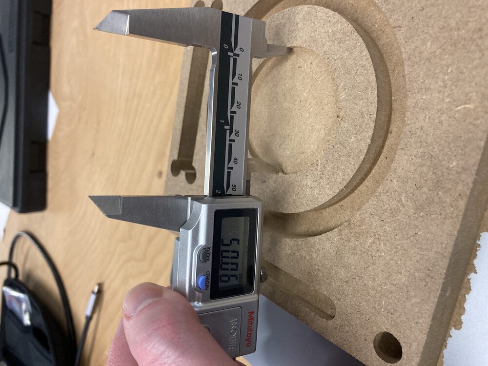
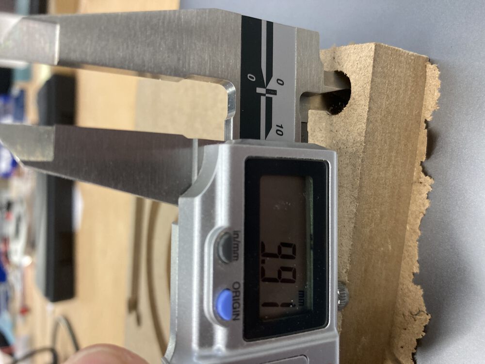
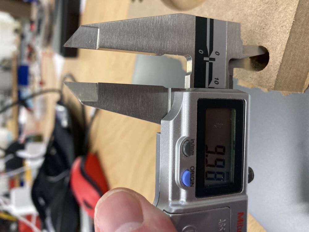
Testing the Runouts
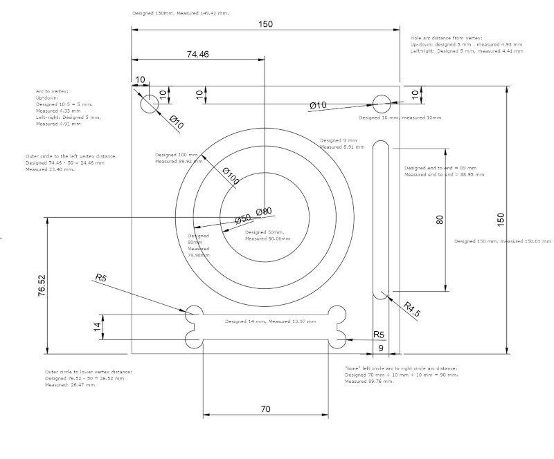
We made a few measurements in order to test for runouts. Example of a measurement.
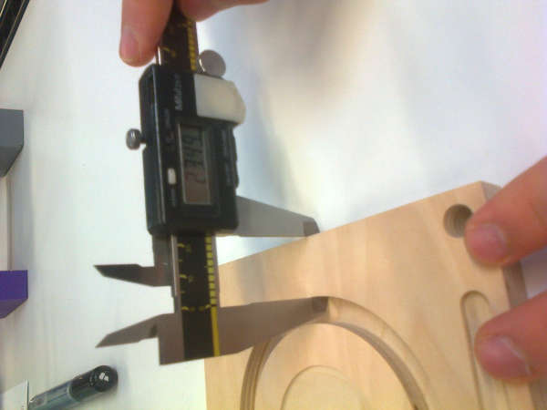 The results are collected in the figure below.
Conclusion
The process of making something big was easy to understand. There were differences between the design and the results, so checking the results by measurements is neccessary. Probably better results could be achieved by better selection of the milling bit and milling parameters with more experience.
Bangor Machine
- Author of this section John Story week 8 assignment
For my solo equivalent of Group Work I thought I should document the safety features of our own machine.
Safety
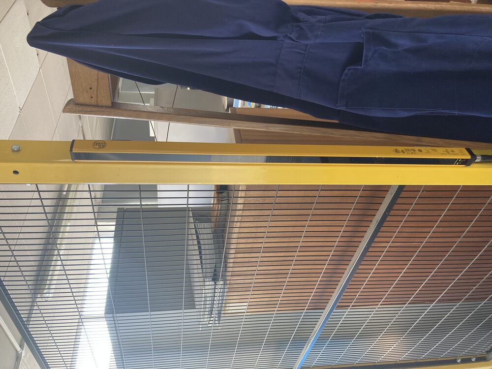
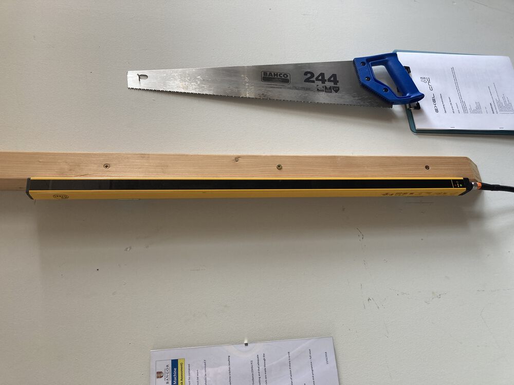
The Router sits in a caged work cell with a single open side protected by light curtain.
 {
{
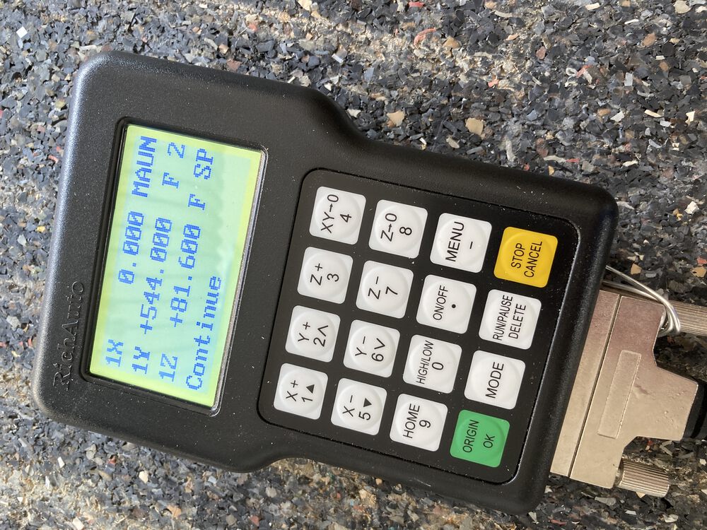
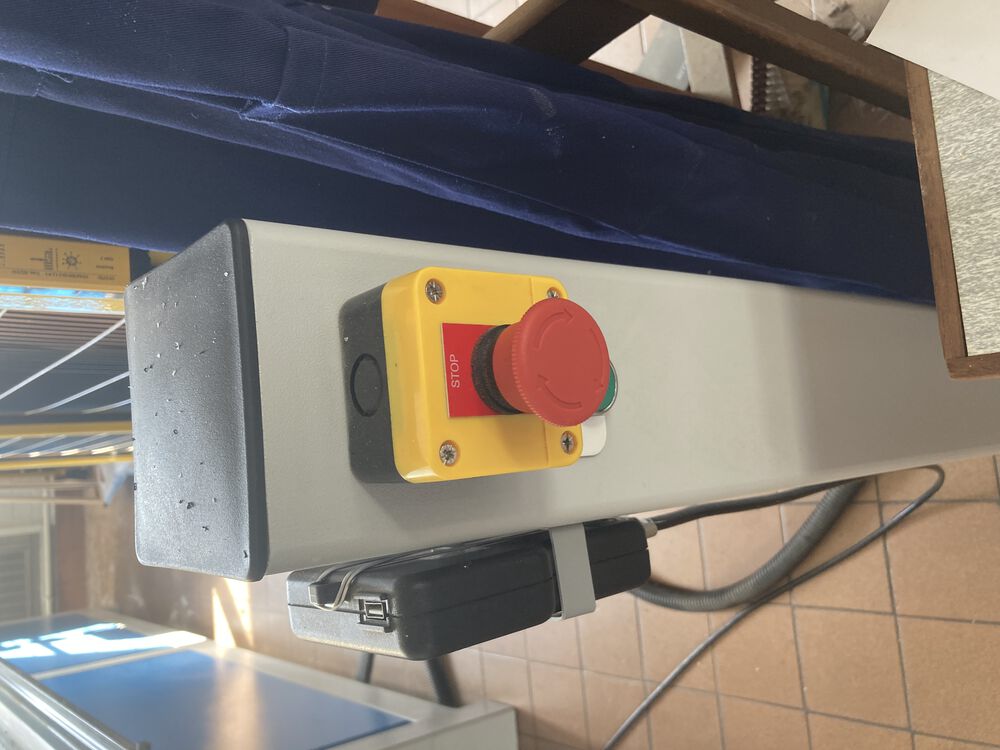
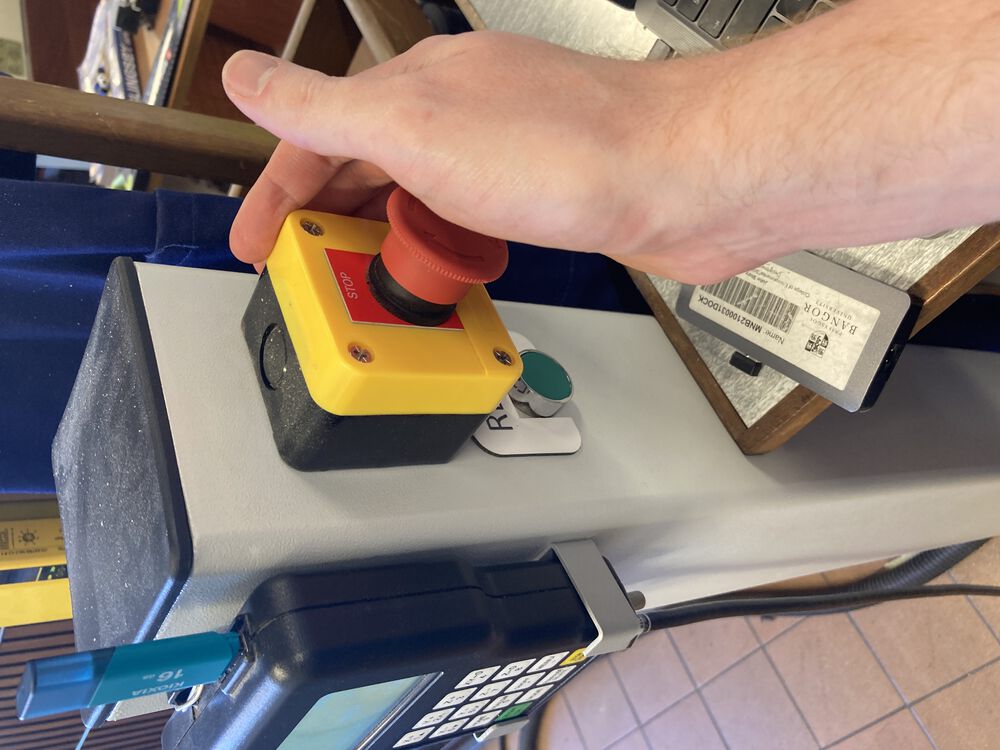
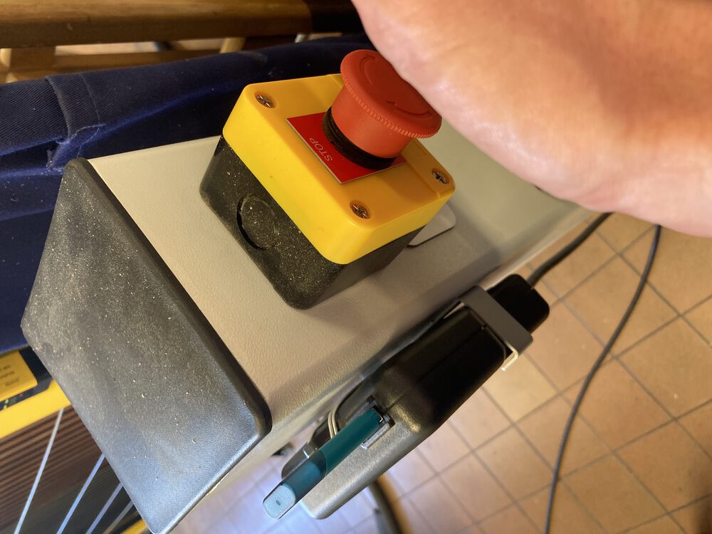
The control pendant in on the outside of the cell mounted to a pillar with an easy to get to stop. If the machine is being driven by a program anyone interrupting the light curtain will stop the machine. This usually happens when someone remembers that they didn't turn on the vac bed which is the only regular control on the inside of the work cell. A stop like this is not recoverable, you need to reset Z0, and restart the milling job.
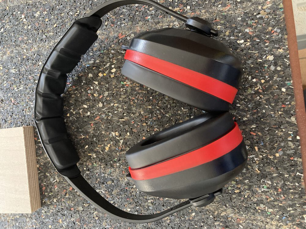
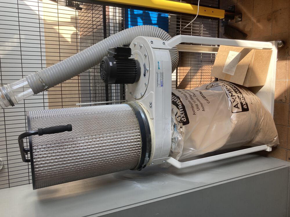
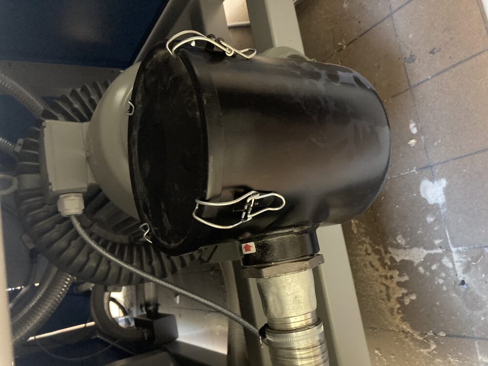
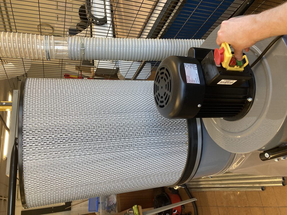
Ear defenders and eye protection are used and suitable extraction. We've upgraded the extractor since this image was taken, installing a similar machine with double the horsepower. A recent survey suggested that the old extract was borderline for the scale of the router.
Another safety principle here is regular review of safety, making sure we are up to date with best practice as it evolves.
Speeds feeds and runout.
We set speed and feeds according to material and tool. Generally a manufacturer of a tool will supply chip loading data that allows your CAM tools to calculate speeds according to number of flutes as a main factor.
As a rule of thumb in timber like products we're running feeds at 4000mm/minute.
Complete run through
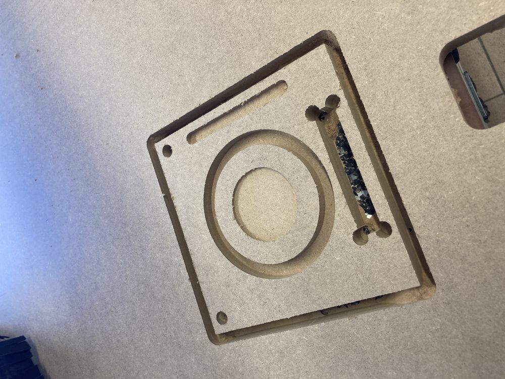
Some of the images here may repeat but below we have a complete run through of cutting the test sample. We used the same file as Oulu did see the link above:
The only changes we made were to accommodate the different thickness of material, and we used fewer tabs.
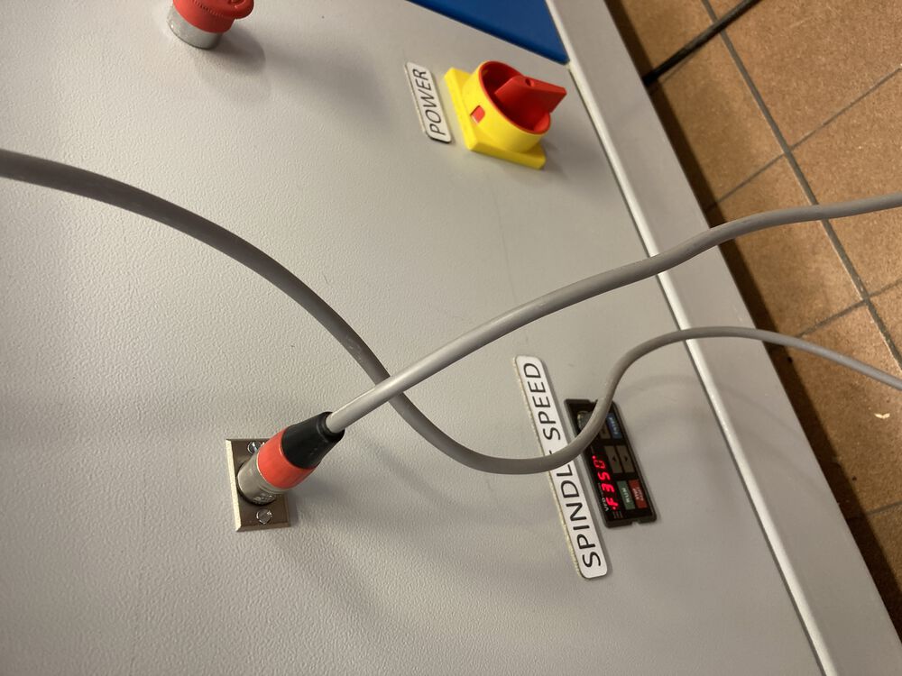
Power is three phase switch on main isolator at back wall
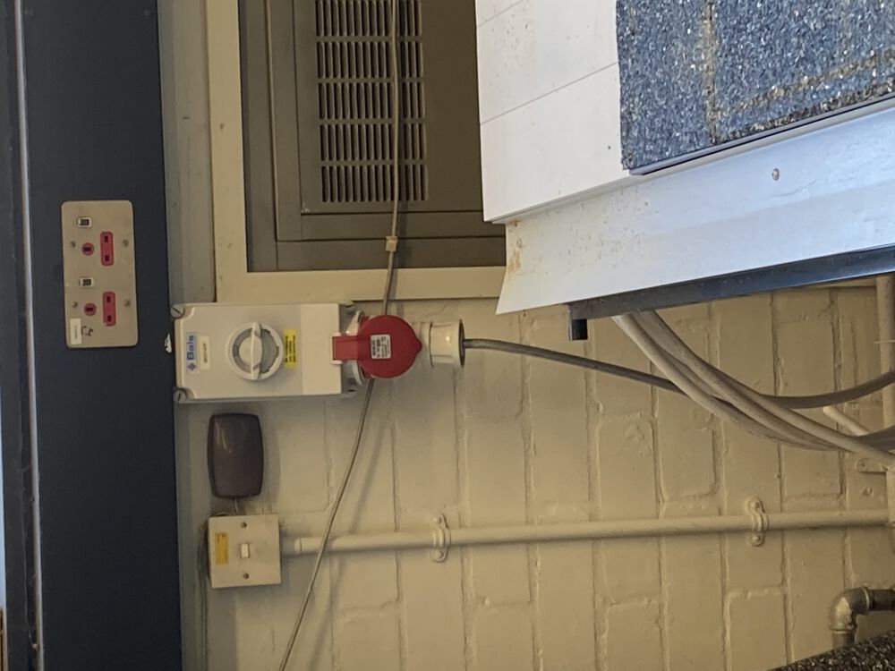
Periodically check the filter on the vac bed system
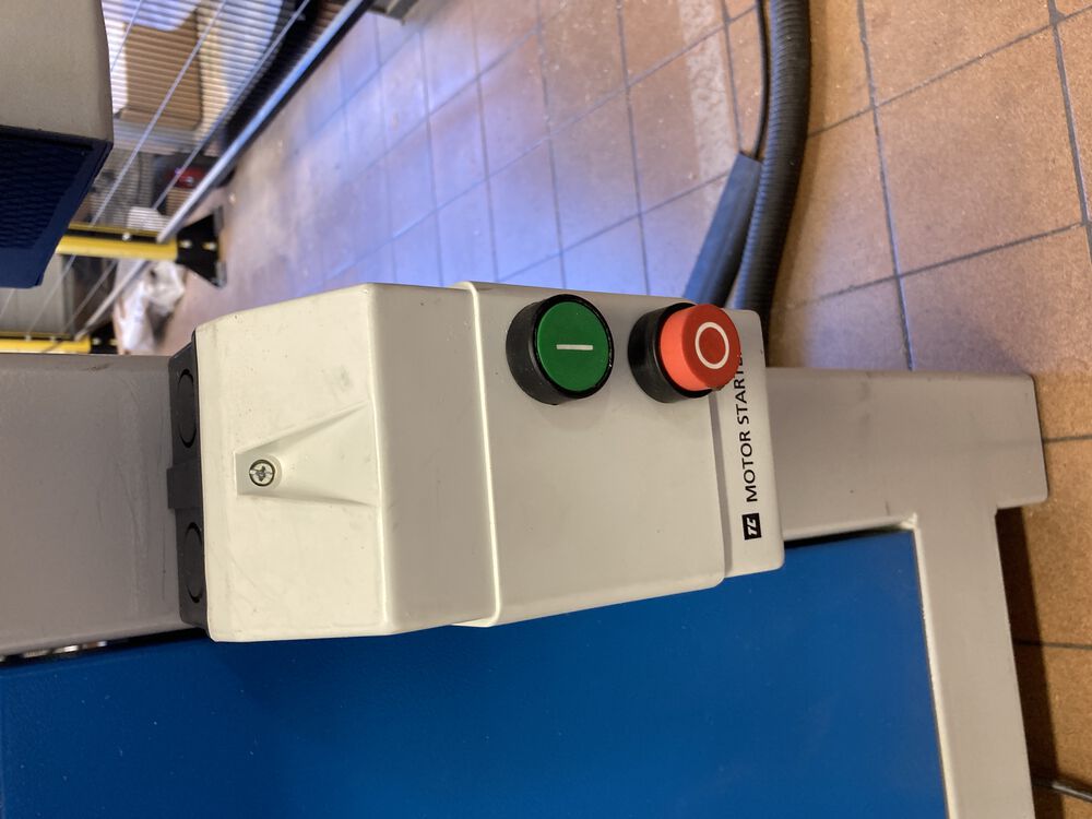
Switch on power at front of machine
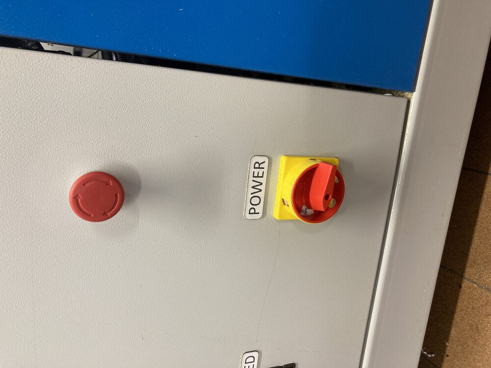
Release red stop if pushed, press green button to activate power to motor drivers

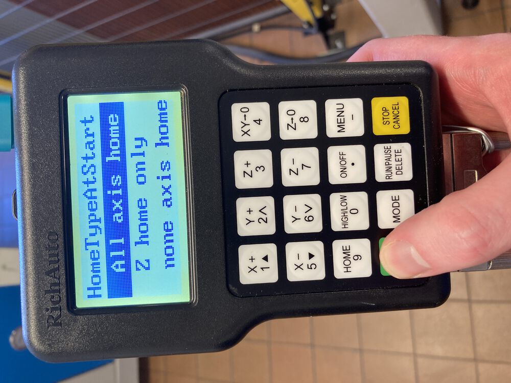
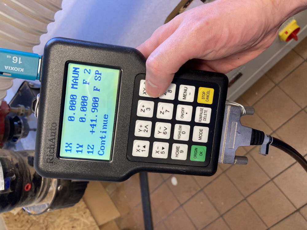
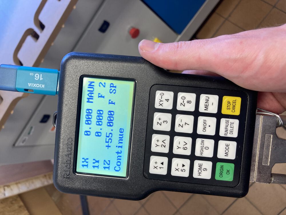
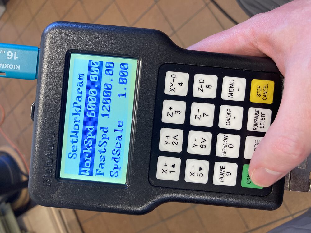
Controller booting

Home All Axis with OK button
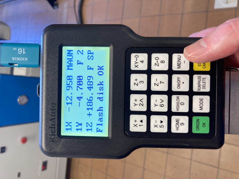
Notice that machine origin is not at zero for G54 coordinate system
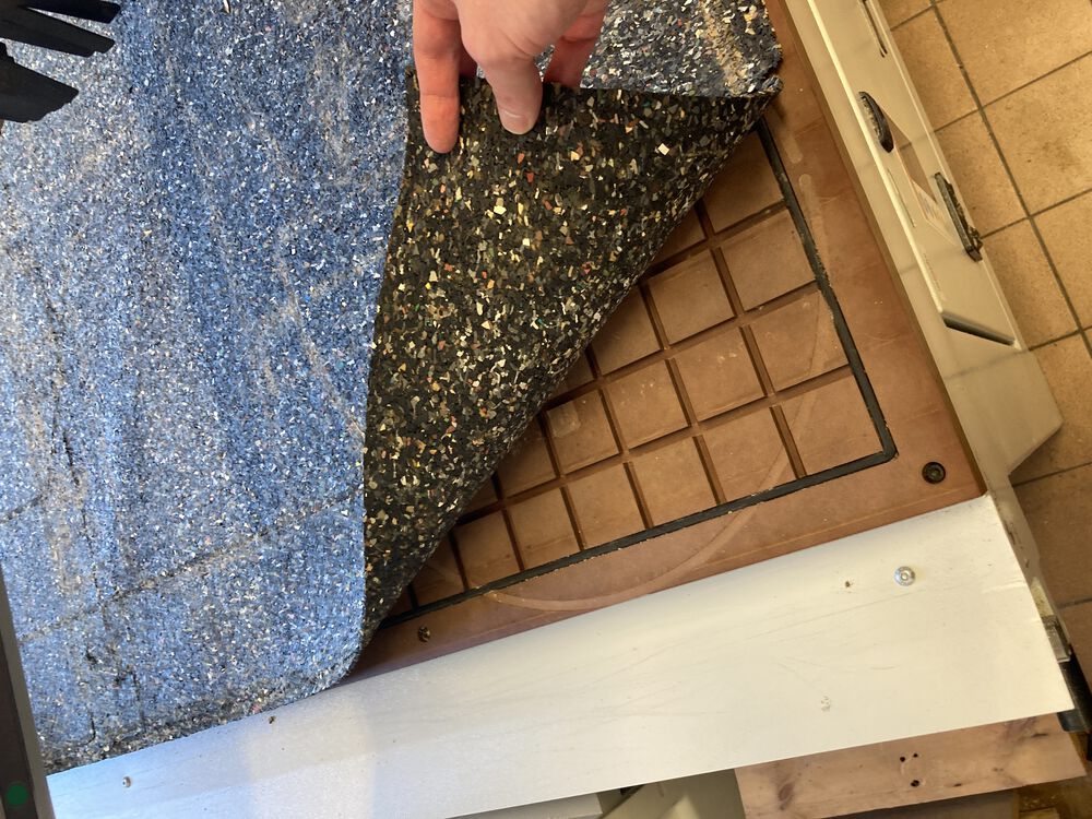
Set seals in vac bed for your material, check plugs to manage vacuum
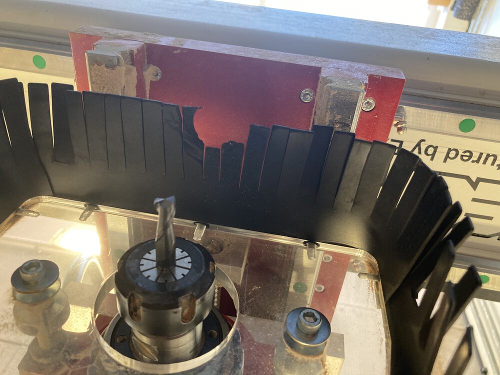
Inserting a tool
Tool in place
Move tool to new origin and press 'XY -> 0' to set G54 origin
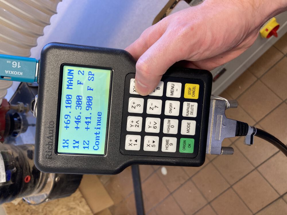
X,Y origin set
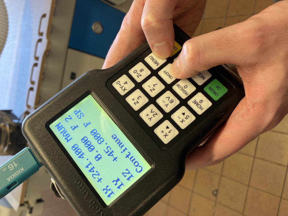
Turn on vac bed before setting tool offset / Z origin
Press 'ON/OFF' and 'MENU' at same time to start auto probe on Z axis
Making sure 'puck' is under tool
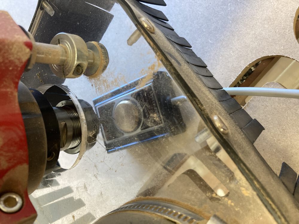
and plugged in
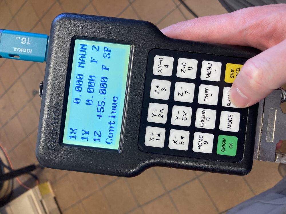
Probe will find Z 0 and lift to park at +55mm
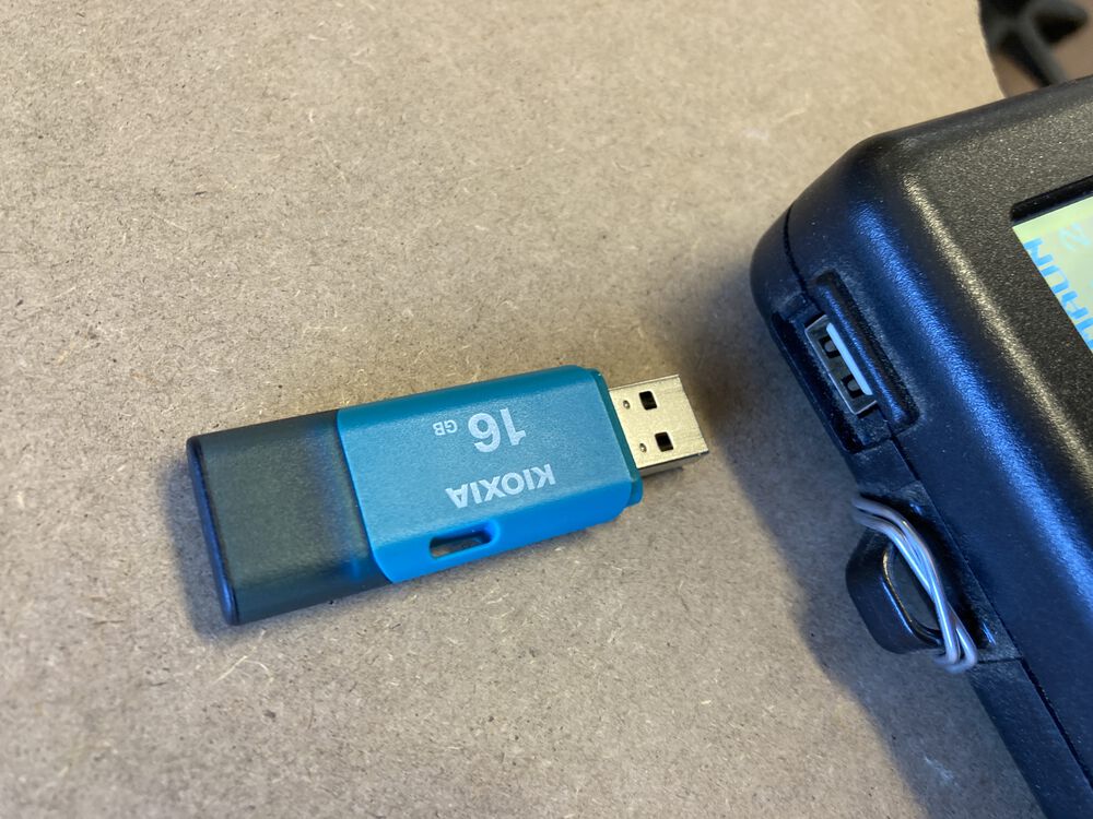
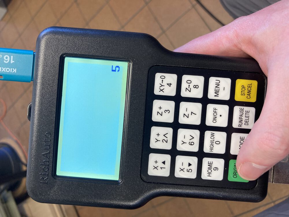
To transfer .nc file to machine plug USB memory stick into top of control pendant
Switch on extract before running job
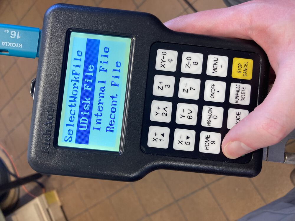
'RUN/PAUSE DELETE' key to pick up file from USB
Select 'UDisk File'
Use Up Down on X keys to highlight file
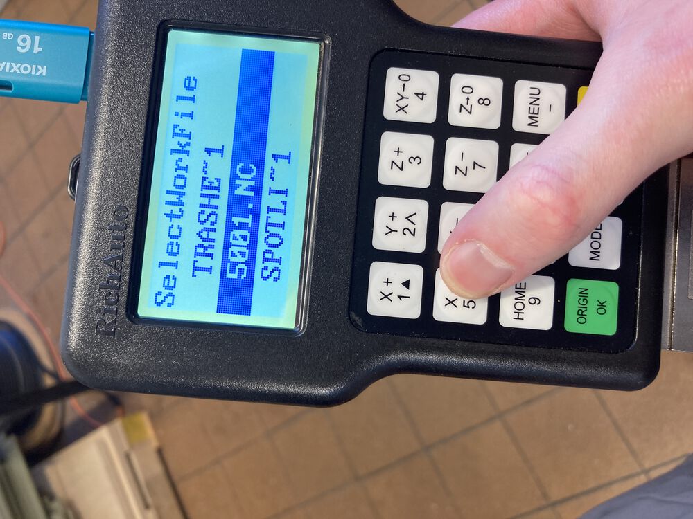
Hit 'OK' to select
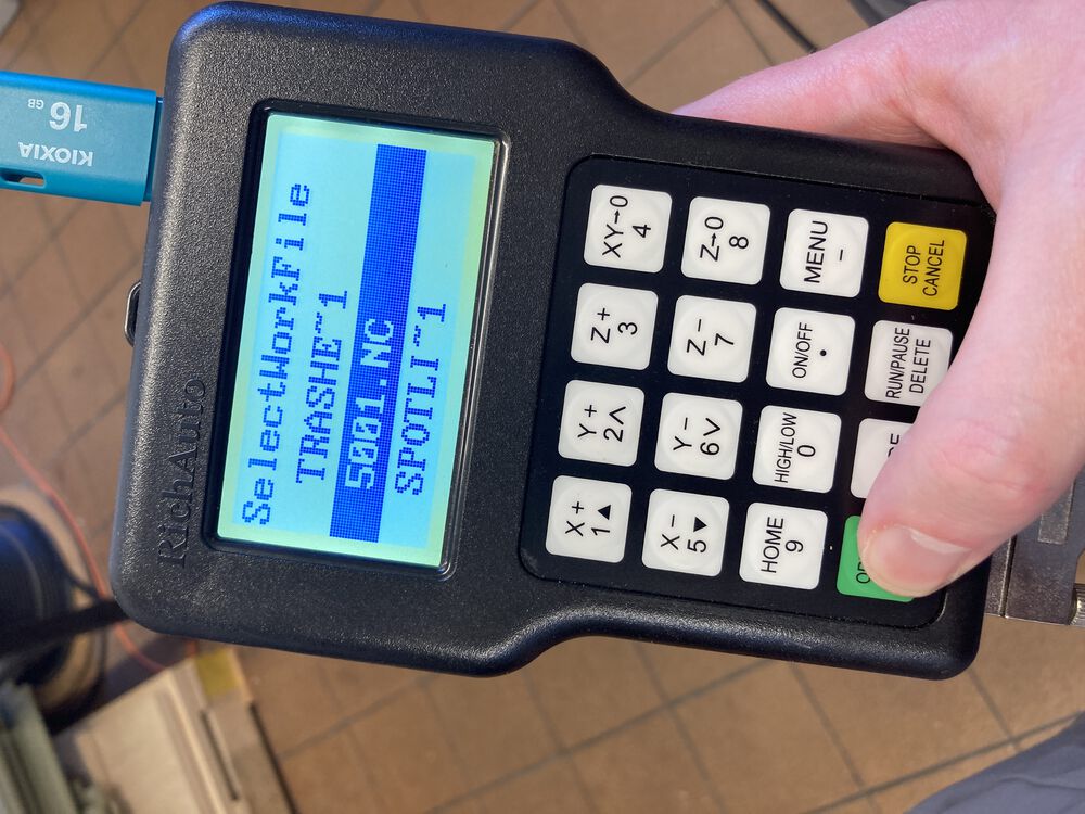
Hit 'OK' again to run selected job
See countdown, stay behind light curtain from now on
Hover over kill switch till we're happy that the job is running correctly
Job complete
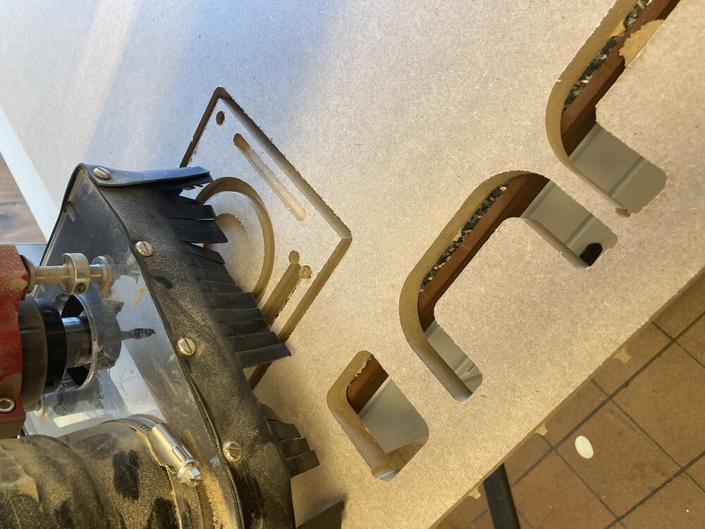
Hoover up remaining dust and remove work from machine
SHUTTING DOWN: Kill drives, switch off all the switched we switched on
RESULT
In most cases the finished dimension in within 0.1mm of design file. Some dimension up to 0.2mm off.