13. Input devices Group Assignment
This week we measured a signal from a Soil moisture sensor.
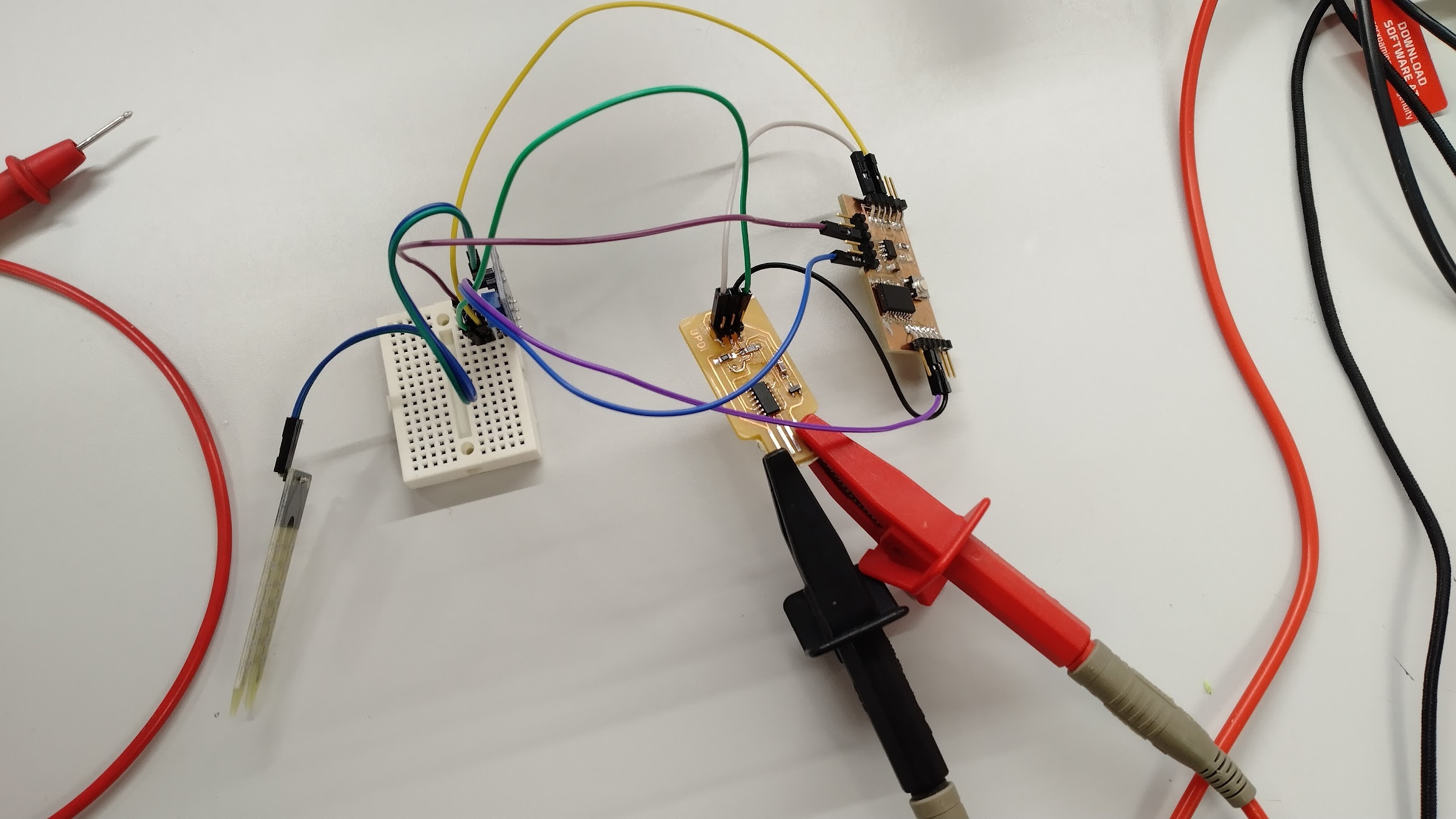
The setup
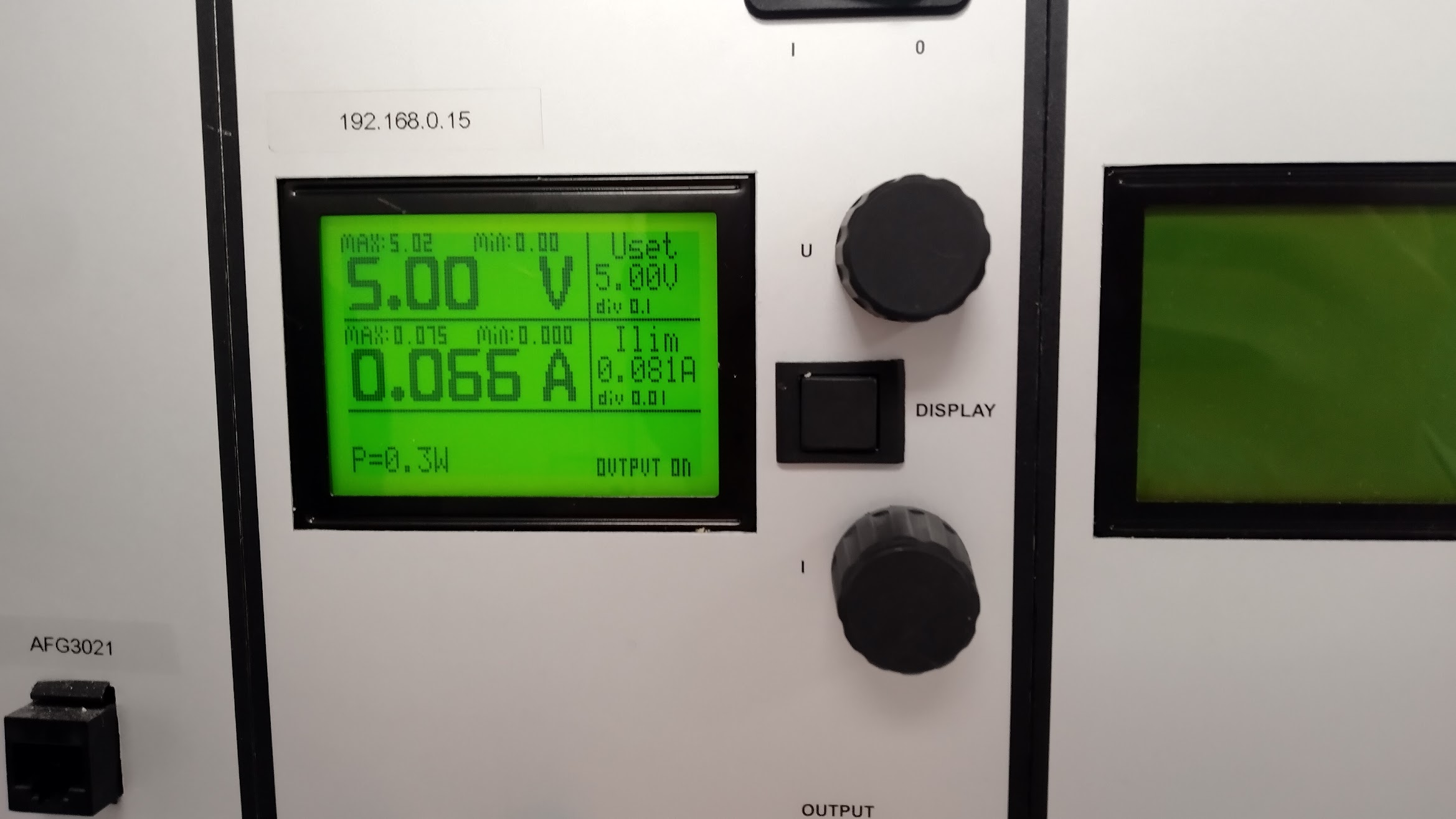
To power the board, 5V were supplied via the UPDI programmer. As there were no real output devices connected to the board, the consumption peaked at about 66 mA when the sensor was submerged. This is simply due to the extra flow of current that goes though the sensor.
This is the maximum current the board drained:
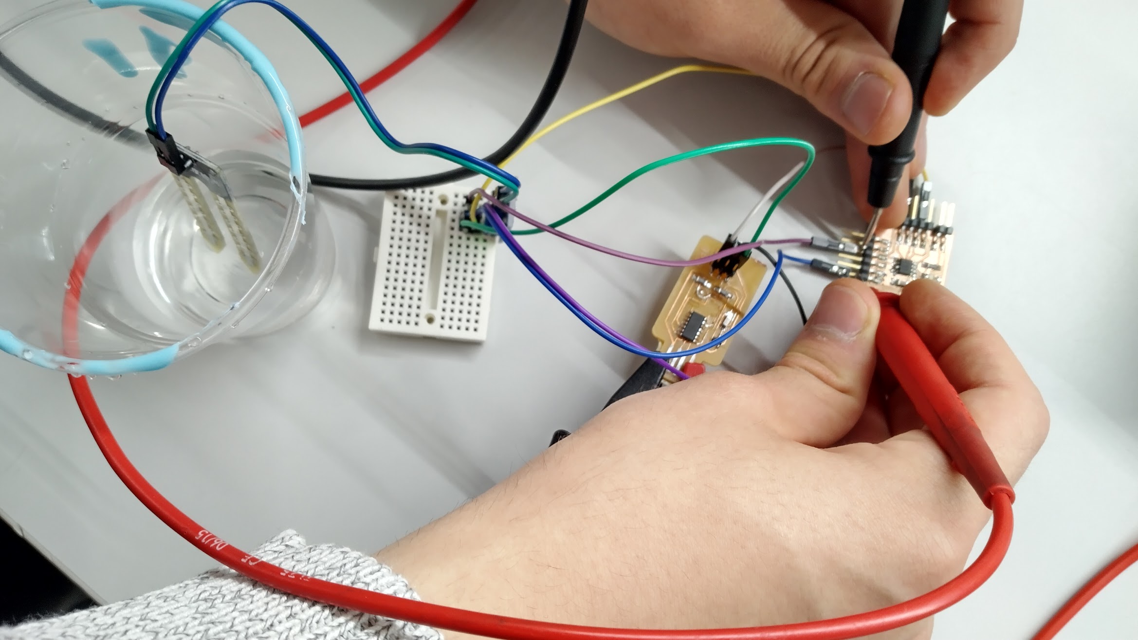
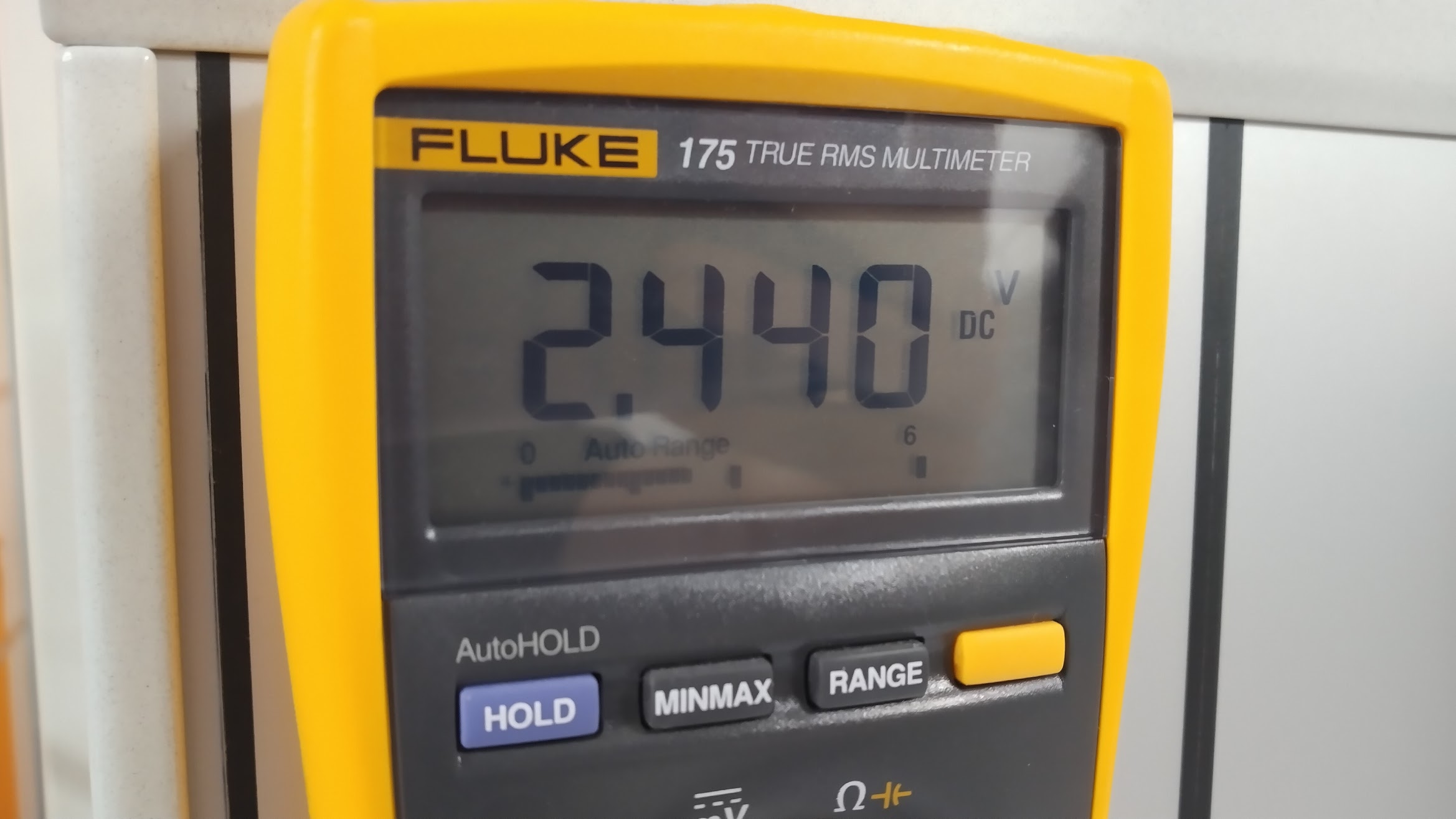
Then we measured the voltage of the ANALOG signal directly comming from the sensor, which surprisingly did not reach the 5V we were supplying. The positive terminal was connected to the PA2pin in my board.
This is the pinout of the ATTiny412, which shows us that pin PA2 corresponds to Pin 5 in the chip.
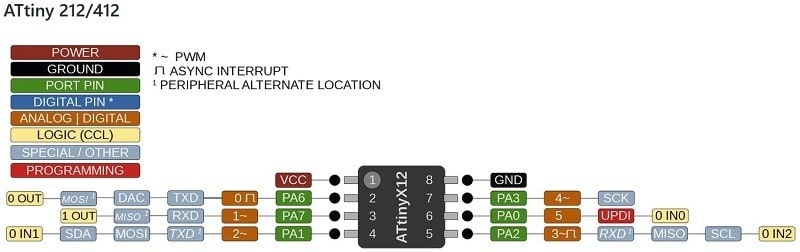
The fact that we did not reach the maximum voltage and stayed hivering around 2.5V was probably due to the potentiometer in the sensor restricting the current.
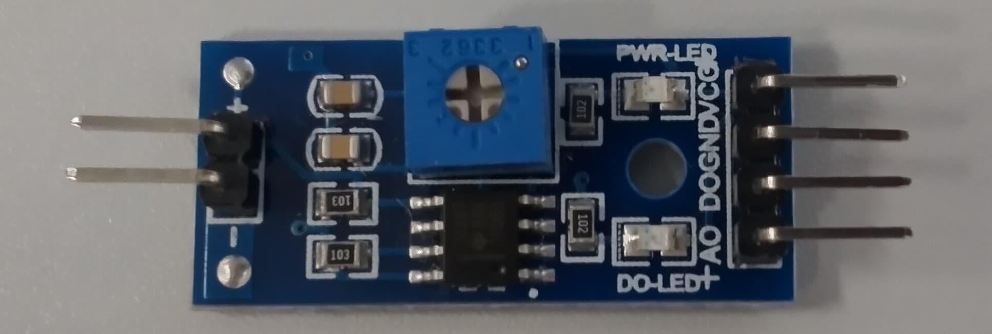
Here you can see the potentiometer. (looks like a blue box with a screw)
The osciloscope
To visualize the digital signal going from the board to the UPDI programmer we connected the positive terminal to PA0, which corresponds to pin 6 of the board and is responsible for the communication between the ATTiny412 and the SAMD11C chips using the Unified Program and Debug Interface (UPDI for short).
"The Unified Program and Debug Interface (UPDI) is an proprietary interface for external programming and on-chip debugging of a device. It is used to program the Atmel MCUs (e.g ATtiny416-816-817, AVR128DA28, etc)."
The first image we got was this:
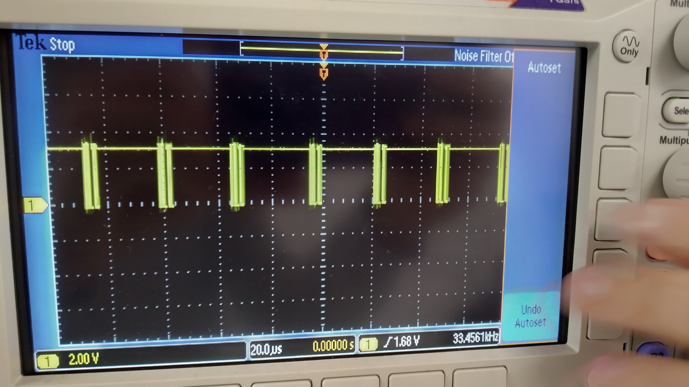
And now with more detail:
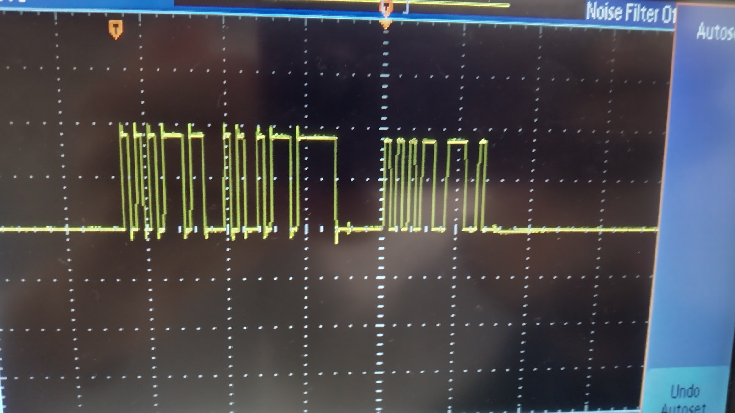
You can clearly see communication going on there. The peaks are 1's and valleys are 0's.
Links
Measuring in Bangor
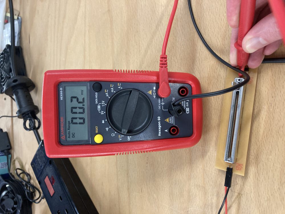
In Bangor we also made an analog measurement, this time a simple sliding potentiometer.
The top of the taper, left of image, is supplied with 5V from an on board regulator. The other end of the taper is grounded.
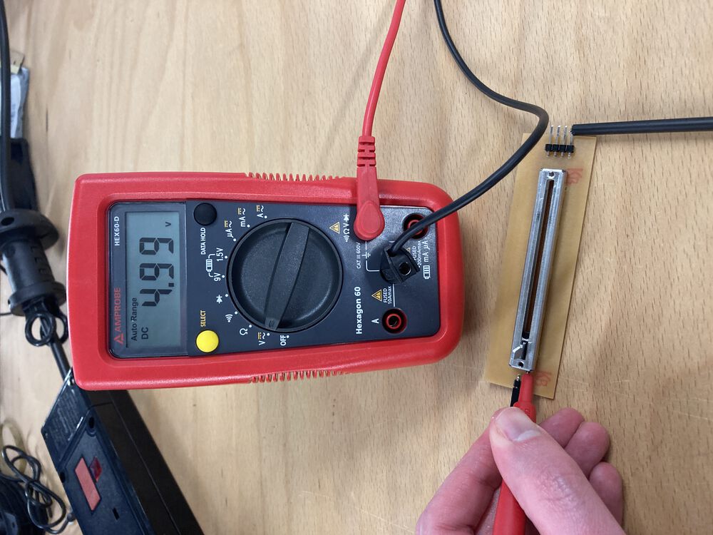
With the wiper fully left we measure 5V at the output.
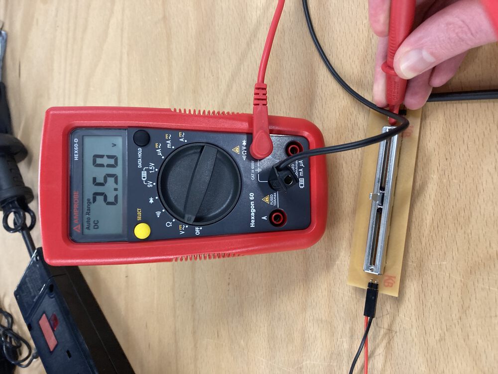
With the wiper half way, we hit on the 2.5V output.
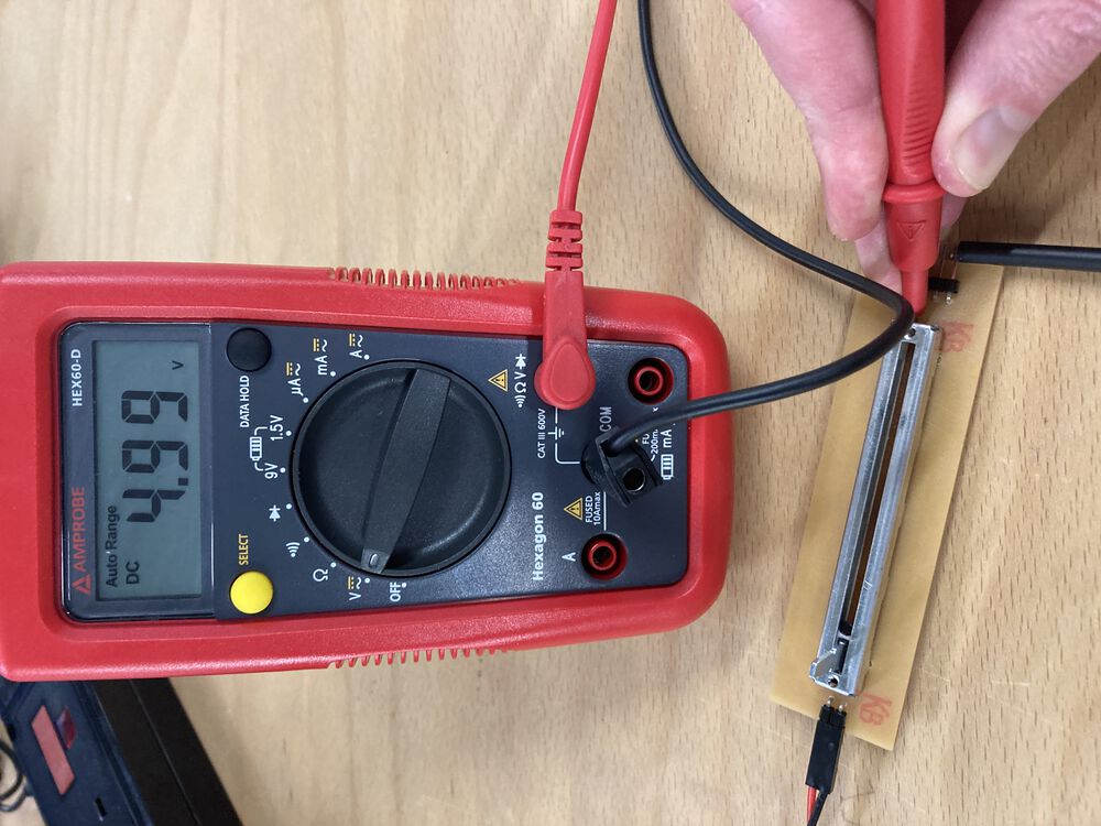
With the wiper full right, no surprises, except there may be a slight mechanical miss-alignment we still see a minor voltage drop. These parts can not be expected to be perfect.
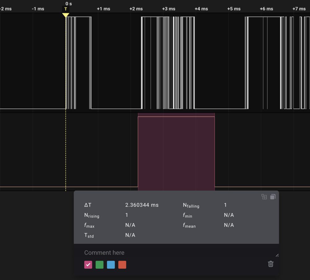
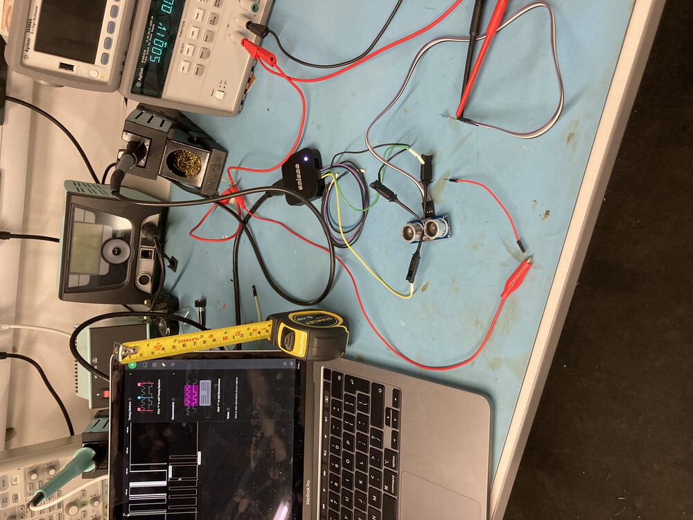
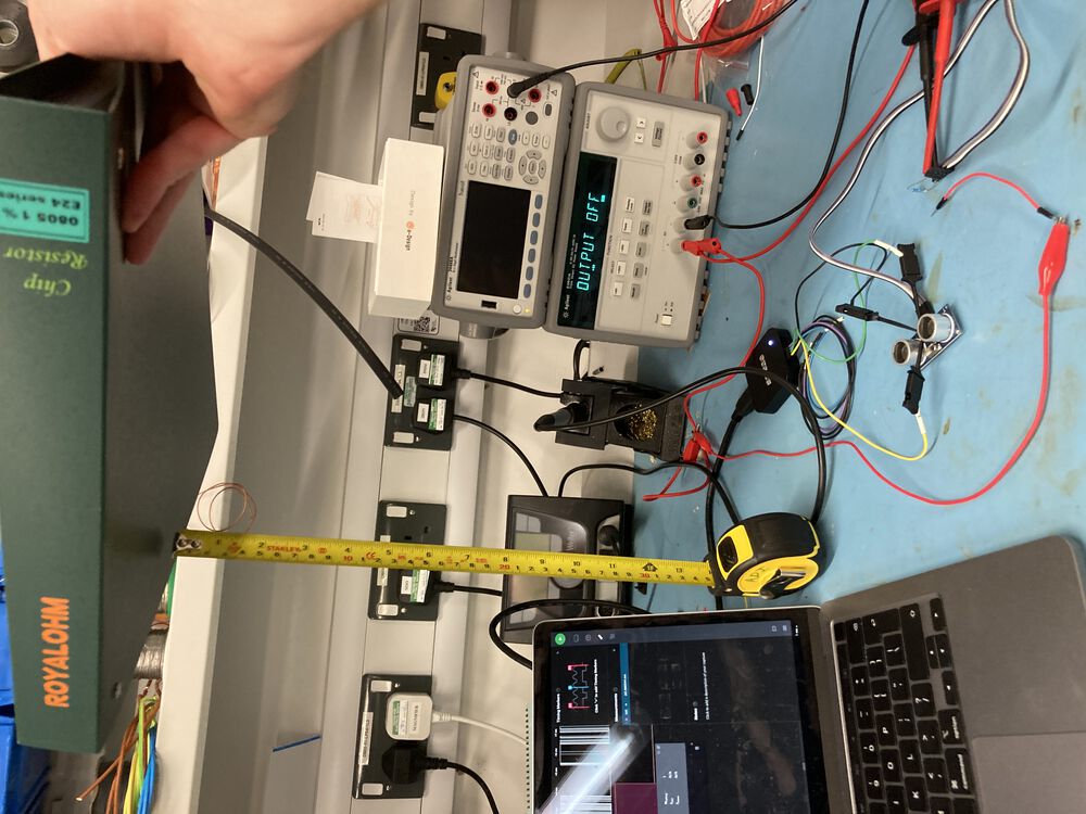
For a Second experiment we got out an Ultrasonic range finder and plugged it into a logic analyser.
We plugged it in to a 5V bench supply.
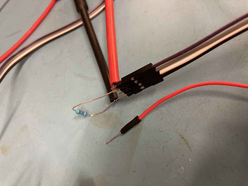
Finding that the trigger input floated high we added a 10k pull-down resistor, we triggered by pressing a 5V pin to the trigger input. (red jumper)
Logic probes attached directly
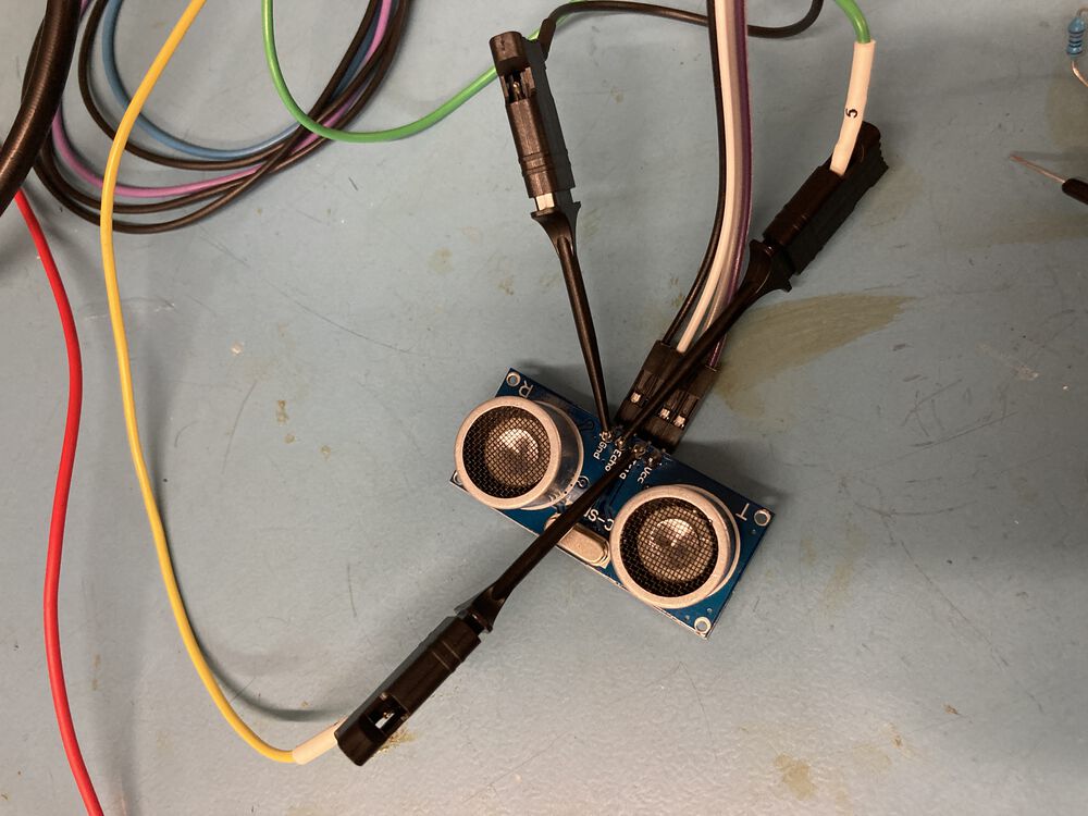
We set a rough distance from the face of the transducers to the surface of a binder, at approximately 20 and 40cm
Results: We can see that the input bounces madly. But we have a good trigger and a resulting output to be measured.
We have a formula from that data sheet: Formula: uS / 58 = centimetres.
In the first case: 1176uS / 58 = 20.3cm.
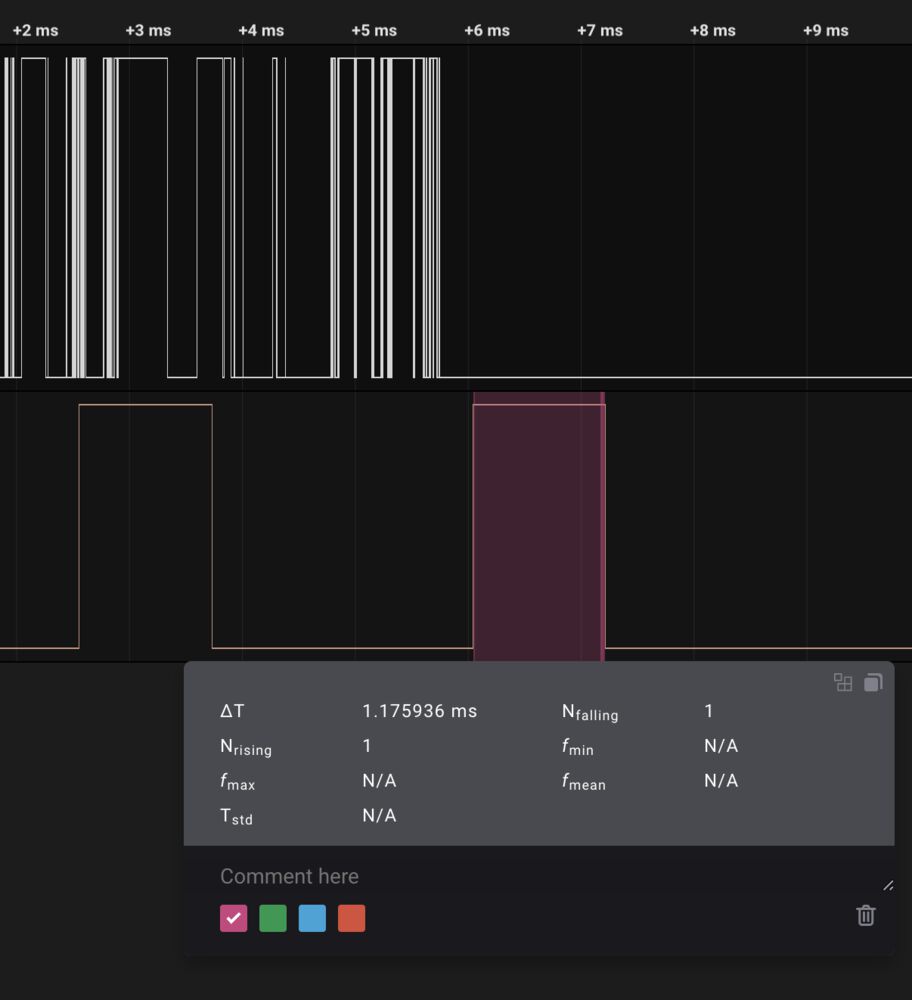
and, 2360uS / 58 = 40.7cm. Both results surprisingly accurate.