Output devices group work: Week 12
This weeks task was to produce output to LCD display.
Group: Antero, Max
Group assignment:
-
Probe an input device(s)’s analog and digital signals
-
Document your work to the group work page and reflect on your individual page what you learned
Measuring the current requrements of the display
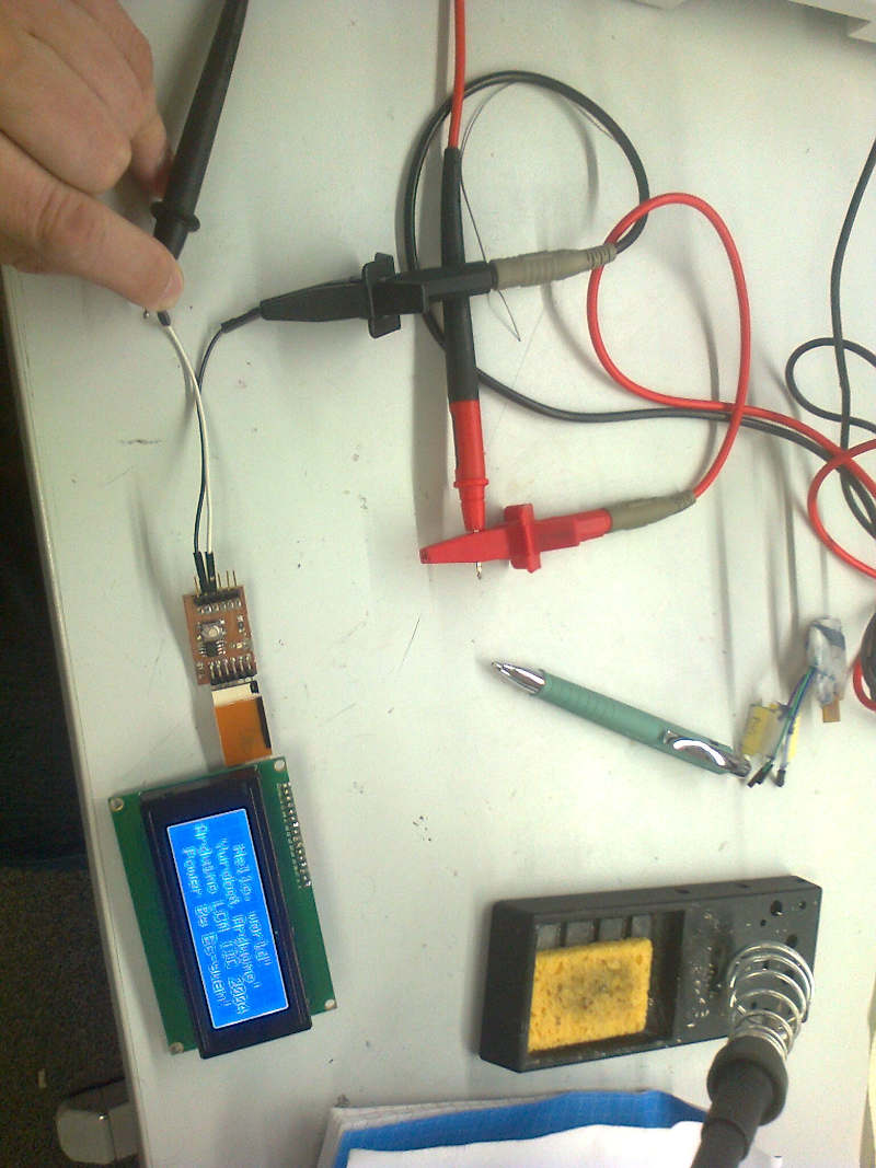
After completing the individual assignment, the board was powered from laboratory power supply. The display turned on and the programming worked.
The white wire marks here Vcc and the black wire marks GND.
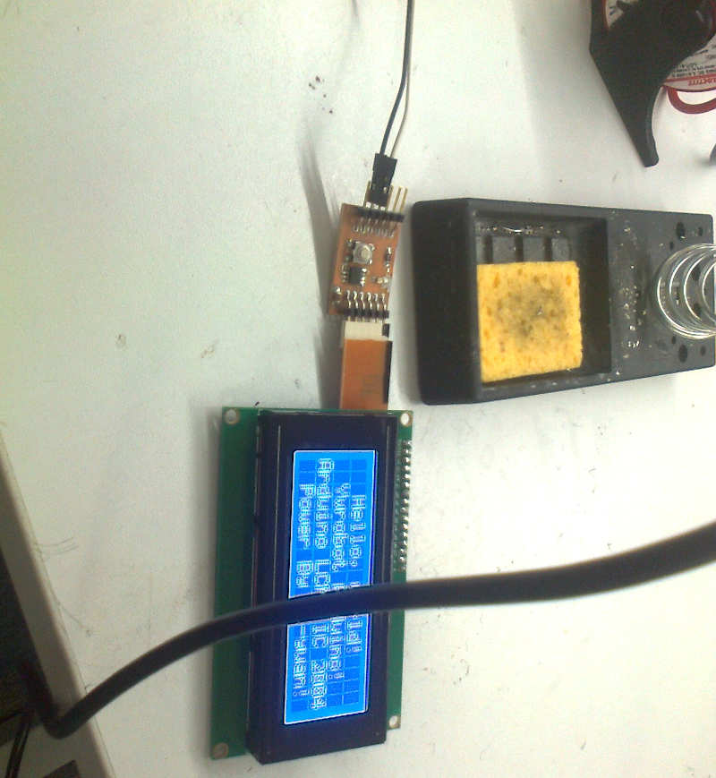
The power supply was set on 4.90V, which is inside tolerances for most of the equipment designed for +5V VCC. The power supply displayed 0.051A current and 0.3W power consumption.
We measured the current consumption by using the multimeter. We connected the multimeter in series with the MCU, as required when measuring current.
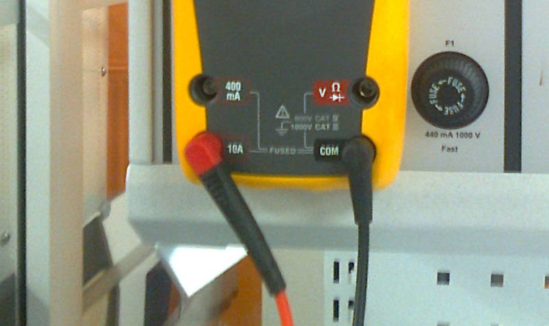
The connection between probe and VCC was held by hand, but the connection proved stable.
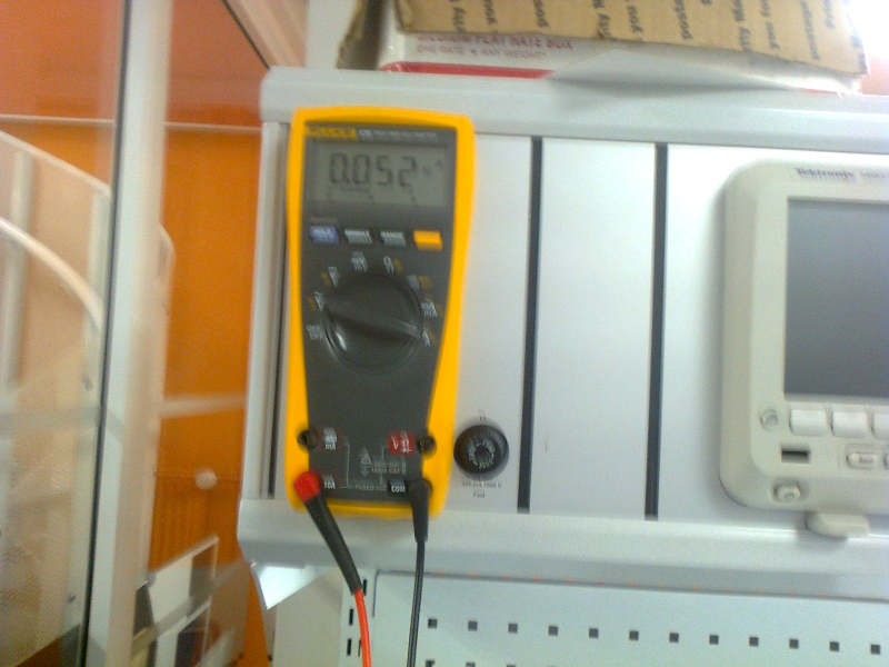
The measured current was 52 mA, which was in line with the 51mA power reading read from the power supply display.
Then we removed the panel from the MCU and repeated measurements.
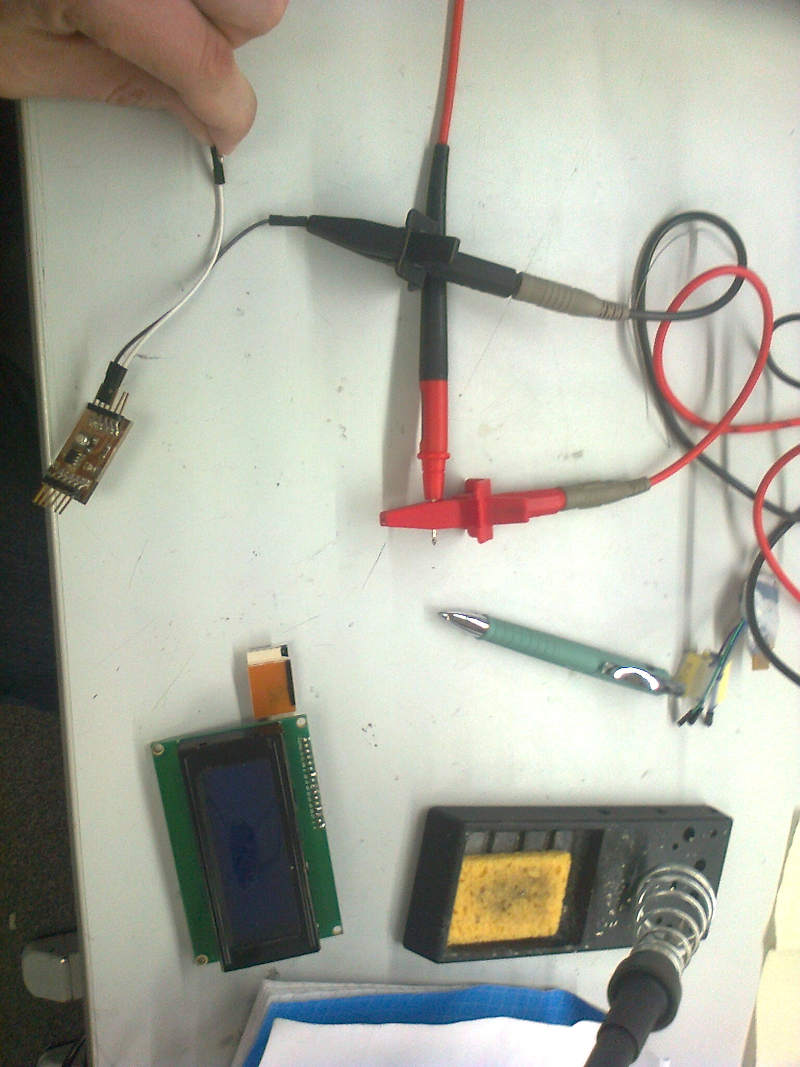
The reading was 11 mA
Results for the measurements
The difference in current when connecting the display, the difference of I was 52mA - 11mA = 41 mA.
The power consumption of the display can be estimated with a formula *P = U * difference of I, resulting in the power consumption of 0.041A * 4.90V = 0.20W.
Measuring in Bangor
Group: John
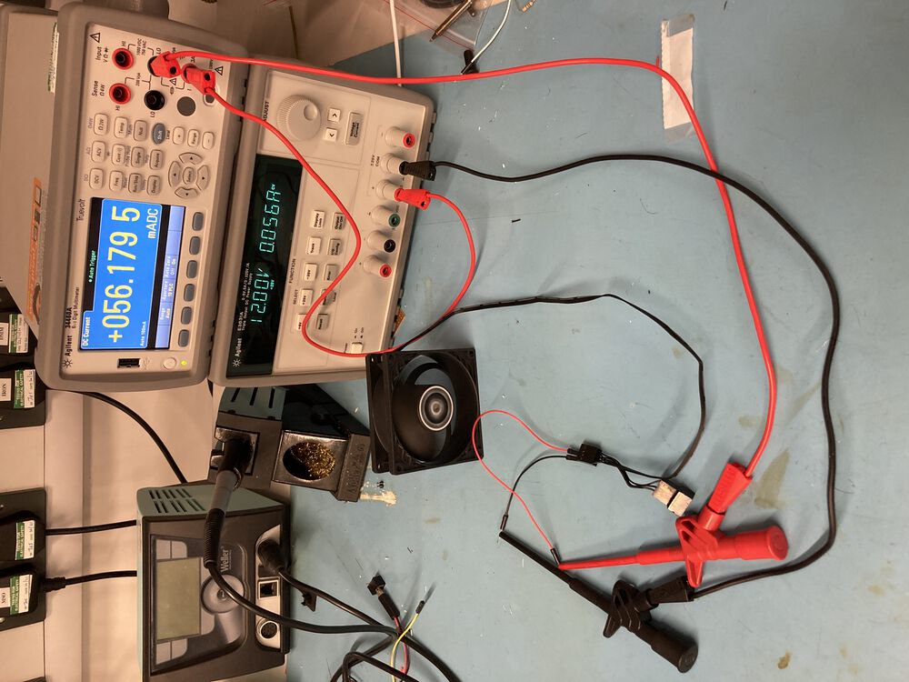
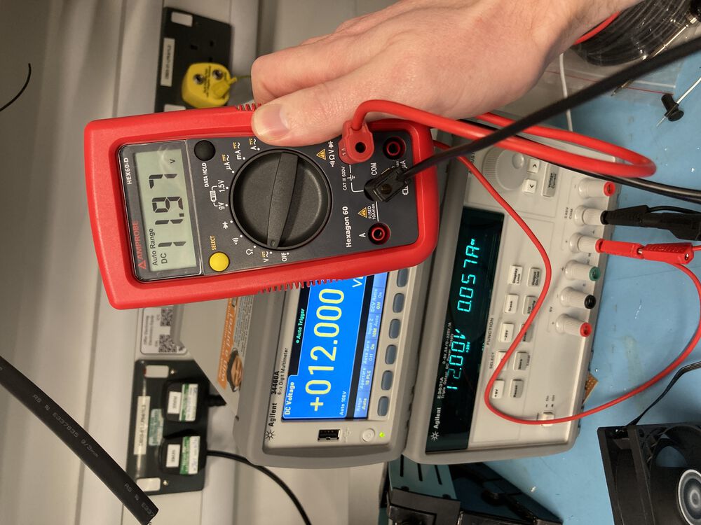
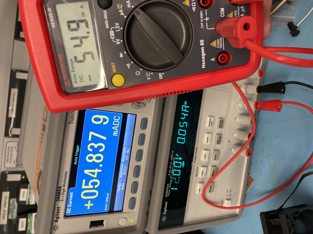
In Bangor I measured the power consumption of the fan I'll be using in my project. Compared the bench-top instruments with an affordable option.
Results: 56mA at 12V. P = IV, 0.056A x 12V = 0.67W
For the current measurement both meters were wired in series with the motor supply. For the voltage measurement both meters were wired in parallel with the motor supply.