14. Networking and Communications
Group assignment: * Send a message between two projects
Introduction
We have here two projects: One made by Max and one by Antero. They are both designed on the Electronics Design week (Max, Antero), however both are at least the second ones manufactured.
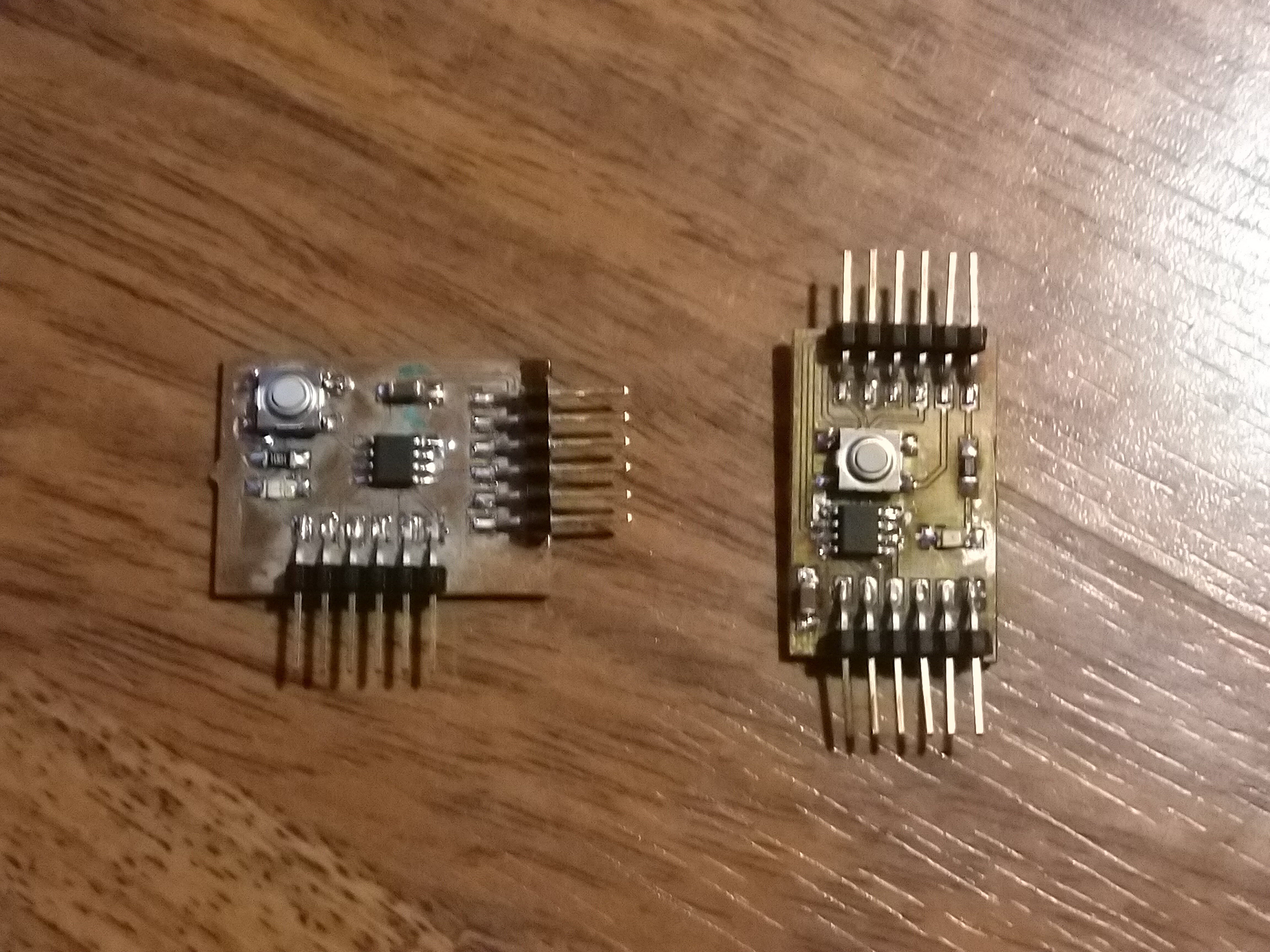
The task was to communicate between projects. Antero wanted to use I2C in his individual work. However, there was no time to make it work in time, so this group work, which is completed later than the individual works, fixes this issue.
I2C bus
I2C bus is a two wire (SDA and SCL)(+ ground) bus. AtTiny uses an implementation which is called TWI for trade mark reasons.
The I2C bus uses open drain technology. The bus requires pull-up resistors, one in both the lines in order to work, No individual device in the bus powers the bus. The bus is kept on high level by the pull-up resistors. Without pull-up resistors there is no high signal level in the bus and the bus just doesnt't work.
So, the general desciption of the bus is two wires between the devices with common GND and two pull-up resistors, one between SDA and VCC and another between SCL and VCC.
Finding the exact value of the pull-up resistors requires some work. Some sources mention values from 4.7 kOhm to 10 kOhm. Too much resistance and the + level in the bus stays too low to be interpreted correctly. Too low pull-up resistor resistance causes too much current to flow thru the micocontrollers or peripheral devices in the bus. This may damage the electronics. 5 mA appears to be a safe level for the peripherals, however microcontrollers can sink 20 mA or 40 mA safely depending on the hardware.
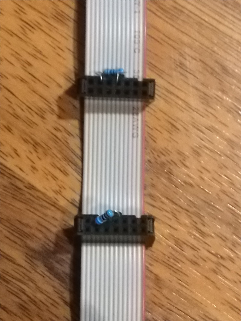
After some testing, the value of 680 Ohm appeared to work. We did not calculate the current, because the value found was a result of iterative decreasing of the value. Higher values just didin't work or resulted only 0xff or 255 values from the bus.
Installing the pull-up resistors to the microcontroller board has its problems. Adding more boards to the bus would require removing extra resistors. This time the resistors were just pushed into the connectors.
There are multiple clock frequency options available for the bus. The highest supported bus speed mentioned in the AtTiny 412 documentation, 1 MHz / 1 mbit/s fast mode was selected. 100 kbit/s standard mode and 400 kbit/s full speed mode are also commonly used. Non-standard speeds can also be specified.
More information about the I2C bus can be found here.
Setup
The cards were inserted in the same bus Antero used in the individual work.
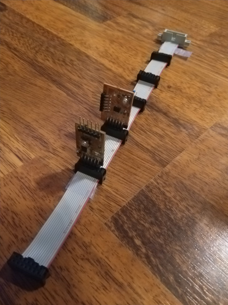
The UPDI programmer and USB to UART cable were connected in the card. Only one USB to UART cable and one UPDI programmer were used, so this required constant switching of five pins while debugging the system. This was very error prone process, because connecting the wires wrong can easily fry AtTiny processor in the cards.
The correct connections for Max's card are shown here:
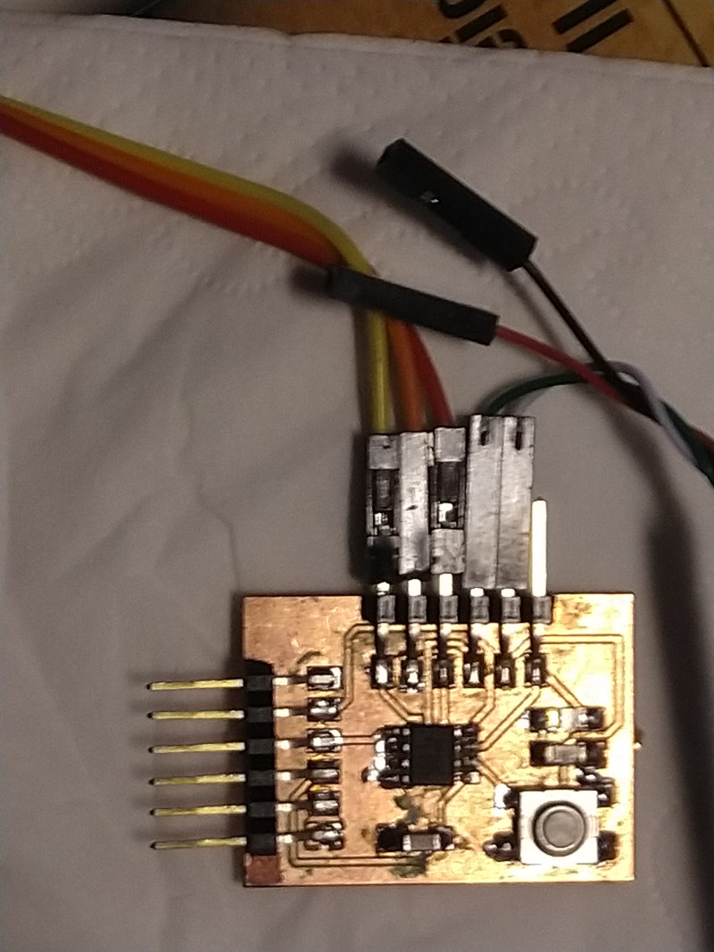
The correct connections for Antero's card are shown here:
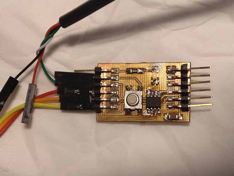
Note that the board is powered solely by the UPDI connector. Yellow wire provides UPDI connection, orange wire provides GND and red wire provides VCC. Green and white wire are for serial port. Serial port was not strictly neccessary for the I2C communications to work, but made displaying the results easier.
The program code
Programming I2C so that it actually worked proved to be challenging. We set the bus frequency to the maximum supported by the hardware (1 MHz) and configured the Slave device to use ID number 10.
There were multiple options available for I2C library, like TinyWireS and TinyWire. However, these libraries had support problems or they didn't include both master and slave. After trying some we ended up just using the plain Wire.h library. The same library was also included in the Output devices week code.
I2C usually has one master device controlling the bus and one or multiple slave devices. The master can send data to the slaves or request data from them.
The slave code
The slave code basically sets the clock speed of the bus, sets the serial connection up, assigns the slave ID and defines functions for receiving and requesting data. The main function has only delay in it, because interrupts starting the function calls defined below would disturb any processing going on in the main loop. The receive function reads all the available data from the bus. Request event just writes the letters as bytes on the bus.
The slave code is shown below:
// I2C Slave Code : Antero Metso Fab Academy 2022 group work - 18.11.2022
// References:
// https://docs.particle.io/reference/device-os/api/wire-i2c/onrequest/
// https://github.com/ControlEverythingCommunity/MS5805-02BA01/blob/master/Arduino/MS5805_02BA01.ino
// https://github.com/Koepel/How-to-use-the-Arduino-Wire-library/wiki/How-to-make-a-reliable-I2C-bus
// https://www.instructables.com/ATTiny-USI-I2C-The-detailed-in-depth-and-infor/
// https://docs.arduino.cc/learn/communication/wire

#include <Wire.h>
void setup() {
  // Set the speed of the bus
  Wire.setClock(1000000L); // A very low frequency of 10000Hz

  // Join as a slave


  // Set serial bus speed
  Serial.begin(9600);
  Serial.println("I AM ALIVE!");
   Wire.begin(10);
  //set handles for the functions
  Wire.onReceive(receiveEvent);
  Wire.onRequest(requestEvent);
}

// Main (empty) loop
void loop() {

  delay(1000);
  }

// Function for handling received characters from the bus.
void receiveEvent(int howmany){
  Serial.print("Master: ");
  while (1 < Wire.available()) {
    char c = Wire.read();
     Serial.print(c);
  }


  Serial.println(".");
}

// Function for handling character requests from the Master

void requestEvent()
{

  Wire.write(byte('O'));
  Wire.write(byte('H'));
  Wire.write(byte('!'));
  Wire.write(('\n'));

}
The Master code
The Master code does most of the processin in the main loop. The messages used in debugging are left in the code, because they are probably going to prove useful for anyone trying to make the I2C bus communications work.
The setup part sets the clock speed of the bus to 1MHz begins the I2C communications and sets up the serial communications.
The main loop uses beginTransmission to start transmission to the slave #10. The letters were sent one by one to make the code as simple as possible. Then the transmission is ended by endTransmission function.
There is a delay recommended after endTransmission. After the delay, requestFrom is used to request data from the slave. This request triggers the function sendin the data in the slave when received. The request from uses (address, quantity) format. It was confirmed that putting the parameters in the opposite order does not work.
The loop for reading the incoming data by using the Wire.available in the loop was found in multiple examples and is a directly copy-paste from one. After reading the data, and printing the data character by character, delay is introduced. The result line sent to the serial is then ended by Serial.println.
The code for the Master part is shown below.
// I2C Master Code : Antero Metso Fab Academy 2022 group work - 18.11.2022
// References:
// https://docs.particle.io/reference/device-os/api/wire-i2c/onrequest/
// https://github.com/ControlEverythingCommunity/MS5805-02BA01/blob/master/Arduino/MS5805_02BA01.ino
// https://github.com/Koepel/How-to-use-the-Arduino-Wire-library/wiki/How-to-make-a-reliable-I2C-bus
// https://www.instructables.com/ATTiny-USI-I2C-The-detailed-in-depth-and-infor/
// https://docs.arduino.cc/learn/communication/wire

#include<Wire.h>
void setup() {
 Wire.setClock(1000000L);
  Wire.begin(); // Join as master
  Serial.begin(9600);
  // put your setup code here, to run once:

}
int received[4]={0,0,0,0};
int reading='@';
void loop() {

// Write data from master to host

//Serial.println("Master writes to 10.");
Wire.beginTransmission(10);

Wire.write(byte('M'));

Wire.write(byte('A'));

Wire.write(byte('S'));

Wire.write(byte('T'));
Wire.write(byte('E'));
Wire.write(byte('R'));

Wire.write(byte('\n'));
//Serial.println("endTransmission to 10: ");
//Serial.println(Wire.endTransmission());

// End transmission to Slave #10
Wire.endTransmission();

delay(70);


// Request data from Master
//Serial.print("Wire requestFrom: ");
 //Serial.println(Wire.requestFrom(10, 4));    // (address,quantity)
 Wire.requestFrom(10,4); // Request data from the Slave #10 (address, quantity)
  Serial.print("Slave: ");
  while(Wire.available()){   // slave may send less than requested
    char c = Wire.read();    // receive a byte as character
    Serial.print(c);         // print the character
  }


  delay(250);
  Serial.println(" ");
}
Results
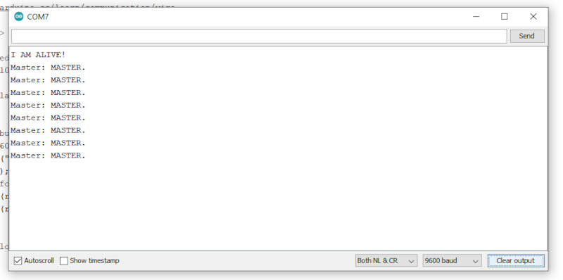
The result from the slave side is shown below. The message received from the master is printed.
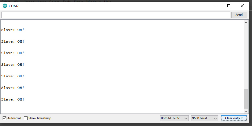
The result from the Master side is shown below. The message received from the slave is printed.
Lessons learnt
The board designed by Max was fried in the process. The line of pins shifted accidentially one pin. However, the function of the system and the communication between two different projects was already confirmed at this point.
The led connected to the logical port 1 was shining dimly when the program runs. The reason for this remained unclear. Because the led was not required in this task, solving this question was left for another time.
I know that there are more appropriate terms we use today instead of master and slave. It is likely that the terminology used will be changed in future standards. However, these terms are at the moment the most descriptive search terms and they are used widely in the examples.