Computer Controlled Cutting Group Task
1 Computer Controlled Cutting
The tasks.
The group assignment task for the Week 4 is:
-
Characterize your laser-cutter's focus, power, speed, rate, kerf, and joint clearance.
-
Document your work to the group work page and reflect on your individual page what you learned.
Laser Cutting theory
In the laser cutter, a computer controlled laser cuts material out by burning. This means that material is always wasted in laser cutting. The laser beam has width. However, the material wasted doesn't equal the beam size. The power, speed of beam, frequency of beam, material thickness and a few other things have an effect on the amount of material actually lost. The lost material must somehow be considered when designing the parts. The concept for taking the amount of the material lost into consideration is kerf.
For more info about kerf and laser cutting of this task in general see Behnaz Norouzi's introduction on Laser Cutting.
Laser Cutter
The group task was performed on Epilog Fusion M2 40 laser cutter.
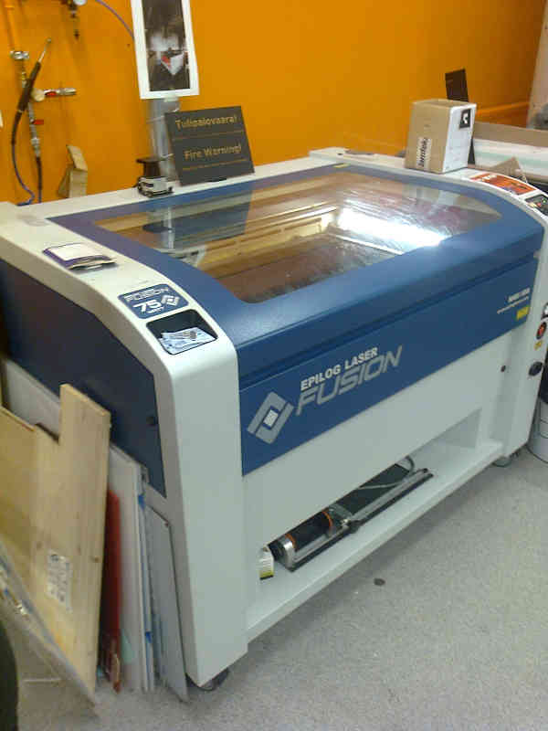
Properties of the cutter
Epilog Fusion M2 40 has a 75 watt CO2 laser. The maximum engraving area of the cutter is 1016 x 711 mm. It has a memory capacity of 128 MB and it weighs 292 kg. The power setting options available from the manufacturer for the CO2 laser are 30, 40, 50, 60, 75, or 120 watts.
More information about the cutter can be found from FabLab Oulu wiki and from the manufacturer's page.
Safety information about the cutter
We were told about the safety information of the laser cutter. It is not allowed to cut unknown or unsafe substances on the laser cutter. plastics containing halogens may produce poisonous gasses when cut. Obviously, the material is cut by a laser beam and common sense should be used with reflecting surfaces.
Ventilation of the gasses is an important thing to consider when using the laser. The ventilation must be turned on by using the appropriate valve before using the cutter. Obviously, the power should be switched on as well. The procedure is documented, but the switches used are not clearly marked. In a safe laboratory space all the switches and valves with safety implications should always be clearly marked. However, the images describing the procedure are clearly visible.
The user must give the ventilation the time it needs before opening the cutter. The ventilation needs some time in order to remove the potentially poisonous gasses. 1 minute waiting time is required.
The cutter should never be left alone to cut. It is possible that the material cut ignites. This possibility is very real. However, fire doesn't always lead to a broken cutting machine. Fire should be put out as soon as possible.
In case of fire, power should be cut by using the unmarked switch. The primary way to fight the fire is to starve the fire by covering the cutter with a fire blanket. The location of the fire blanket was shown to us. If this is unsuccessful, the secondary option is to use the fire extinguisher. For more info about the safety, please see FabLab Oulu Safety instructions.
Setting up the Laser Cutter
After the safe and approved material cut is inserted in the cutter, there are two things to do: Jog and Focus.
Jog is used for positioning the starting point of the cutting. The origin is top left. User selects Jog and then uses the joystick to move the red guiding laser pointer to the starting upper left corner of the job on the material. It is possible to get the dimension information of the job from the software before making the decision where to cut. The starting point is set by pressing the joystick down. The LCD screen shows information. Note that the lid must be shut before moving the laser.
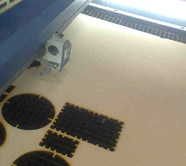
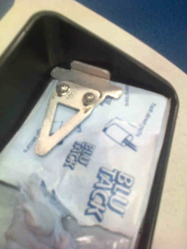
Focus is needed in order to tell the cutter the distance between the laser and the cut material. The cutter can't measure the distance by itself. Focus is selected from the control panel. A triangular tool is inserted to the laser. Joystick is used to set the distance so that the tip of the tool just touches the material. Then the joystick is pressed and the LCD screen shows information.

After the focus is set, the triangular tool must be removed and put on it's place on the nearer left corner of the cutter. Note that the lid must be closed before adjusting the focus.
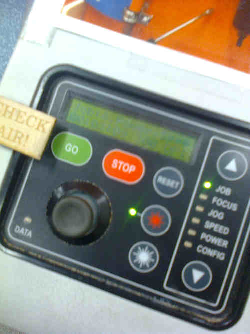
After the laser is in focus and position where to start the cutting is set properly, the cutting can start. The cut job is selected by selecting the first Job from the control panel of the cutting machine. The joystick is then used for selecting between different jobs sent from a computer. The job number and information is shown on the LCD screen. The selected job is started by pressing the green go button. The job can be stopped by pressing the red stop button.
There is also a button for turning the potentially dangerous laser off.The 1062 nm laser is far in the infrared area, so you can't actually see it, if the case breaks in case of the explosive failure. Note that the lid must be closed in order to start the job.
Printing the cutting file from the computer
The integrated print server in the cutter receives instructions on how to cut in the form of a PDF document. The PDF documents can be produced for example in Inkscape.
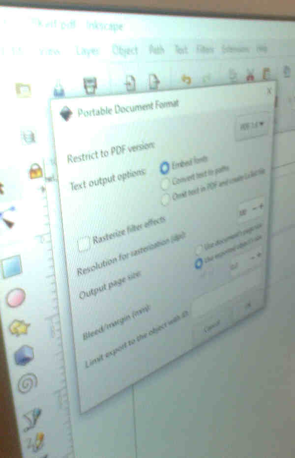
The design can then be cut by printing PDF documents in the Acrobat reader. The printer driver for the laser cutter takes the control.
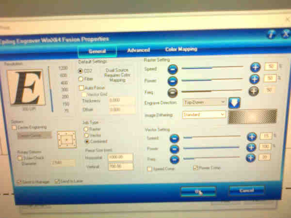
In the general settings, the resolution is usually set to 300. It is possible to differentiate between vector cut, raster engraving or just use both. The reason why it is sometimes important to print only one type of data is for example a situation, where cutting is done first and raster printed with different options later. The line width about 0.020 mm should be used for vector data for automatic cutting.
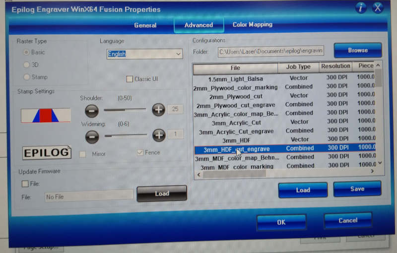
The information about the material type and thickness must be set in the driver in order to get the job done. These selections can be done in the Advanced printer driver menu. For example, for 3 mm MDF engraving/cutting the 3 mm mdf engraving/cutting configuration file should be selected.
Colors in the PDF can be used for separating for example different power settings. The settings can be described in configuration files as well. The info about the selected color to parameters mappings can be viewed and adjusted in the Color Mapping menu.
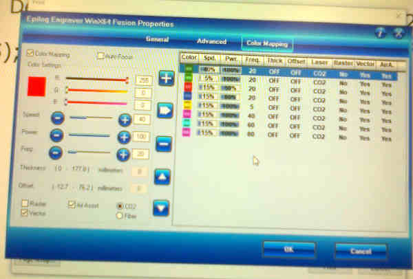
These options were used in our group work.
What we did?
After watching the quick presentation of the cutter, we did three things with the Fusion M2 40 laser cutter.
(0) We tested the laser cutter.
(1) We tested the laser cutter with different resolution settings. The higher resolution image obviously burned too much with the current configuration file.
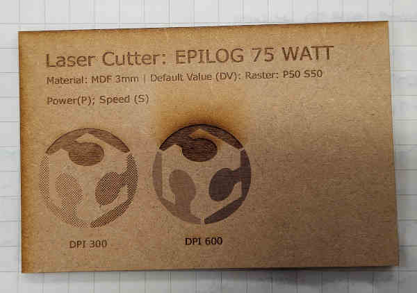
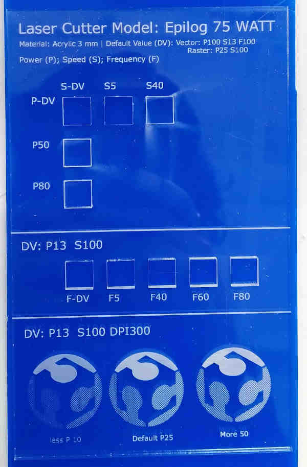
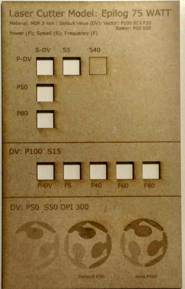
(2) Then we cut a "Laser Cutter Model: Epilog 75 Watt" model to 3 mm MDF. Then we printed the same model to 3 mm Acrylic. The designs were edited in Inkscape and different data was entered there. The idea was to see the differences in power and frequency settings.
The models were cut by first drawing the vector part and then adding the raster part to the power setting test with different power levels.
First try to do the MDF test failed:
See the images for parameters used in cutting:
Power:
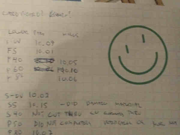
For acrylic, S-DV and S-5 settings cut through. S40 did not cut through the material. P50 did damage the material, but did not cut through. P80 almost cut through.
Frequency: Changing the frequency, number of laser pulses per second, obviously changes the power received in the material accordingly. In this case, all the frequency settings, both in acrylic and in MDF managed to make detachable pieces.
DV: P13 S100, all the squares were cut. For raster images, default was P25. We tried a lower power setting (P10) and a higher power setting (P50). The higher setting cut more and the lower setting cut less. The image was the most visible on default setting.
The frequency settings didn't seem to have much effect on MDF, all the settings were powerful enough to cut through and the same on acrylic and it was possible to remove all the pieces. The higher the frequency, more power will be absorbed by the material. More power means more cutting power.
See the videos for vector data cutting and raster data engraving.
Data of the measurements.
(3) Then we cut models for calculating kerf on both 3 mm MDF and 3 mm Acrylic and calculated the kerf.
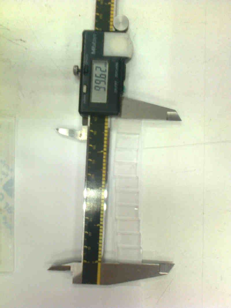
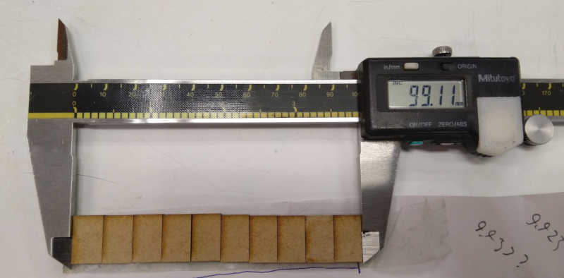
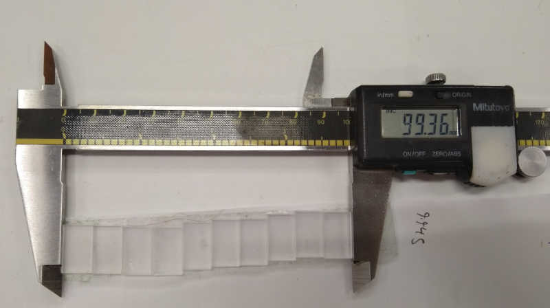
The tool we used had problems. Lightly tapping the tool increased the measured value. Tool used for the measurements
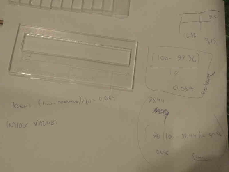
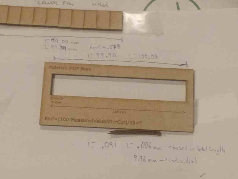
We measured the width of 10 pieces and calculated kerf = (100 mm - MeasuredValueAfterCut[mm])/10. 100 (mm) refers to the original design size of the 10 rectangles and 10 refers to the number of rectangles.
The MeasuredValueAfterCut for acrylic was 99.36 mm, so the calculated kerf value was 0.0064.
After doing the measurements again, the MeasuredValueAfterCut for MDF was 99.24 mm. The calculated kerf for MDF after revised measurements was 0.0076. Originally, we calculated value for kerf to be 0.073 mm.
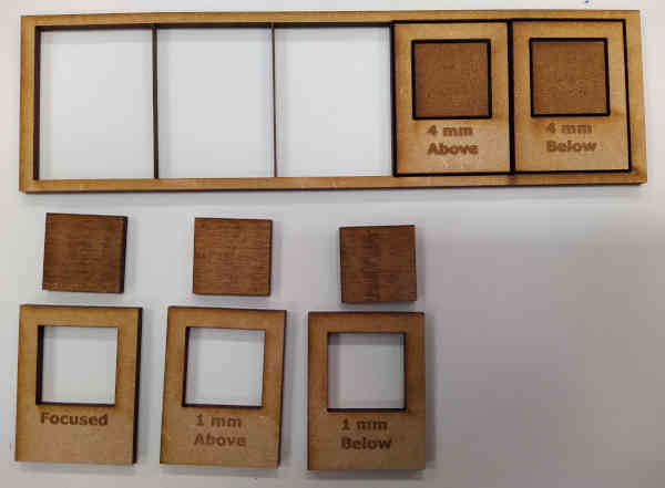
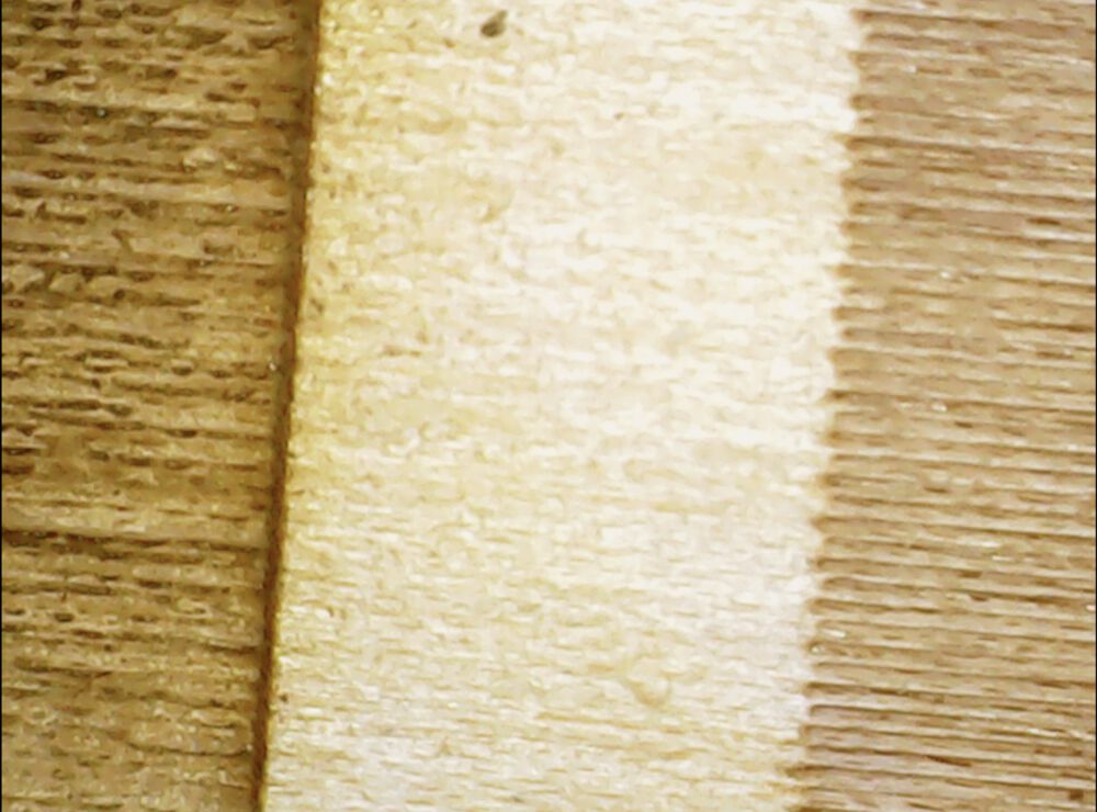
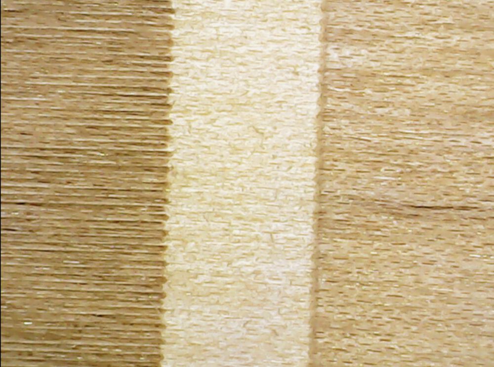
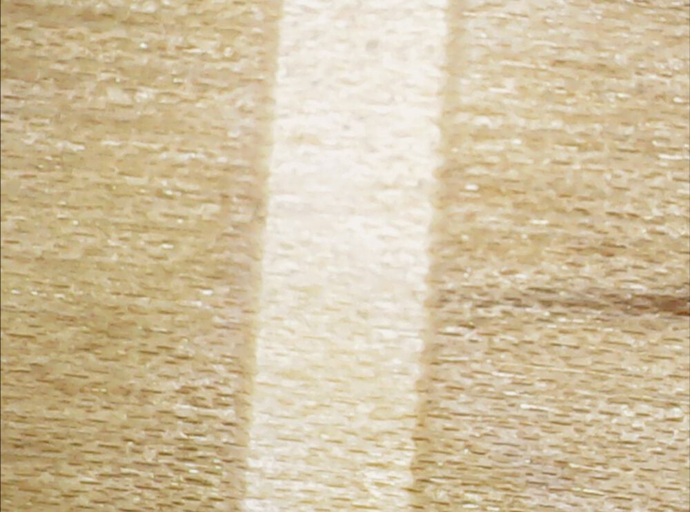
 (4) We printed raster data with focus and without focus.
The focus / out of focus numbers are engraved. When the laser was out of focus, the text and shapes appeared blurry. When the laser was on focus, shapes appeared sharp. This was because the beam width is sharpest at the focus point. Moving from this point upwards or downwards widens the beam. The sharpest resut is achieved when the laser is on focus and that's why it is important to calibrate the focus before cutting.
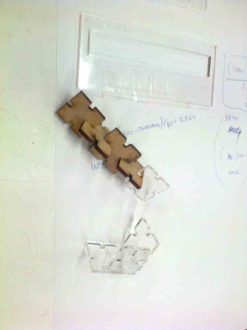
(5) Then we applied the calculated kerf and we cut the demo construction kit on both 3 mm MDF and 3 mm Acrylic. The kerf value was changed in Inkscape. Changes in Inkscape
The new set was cut
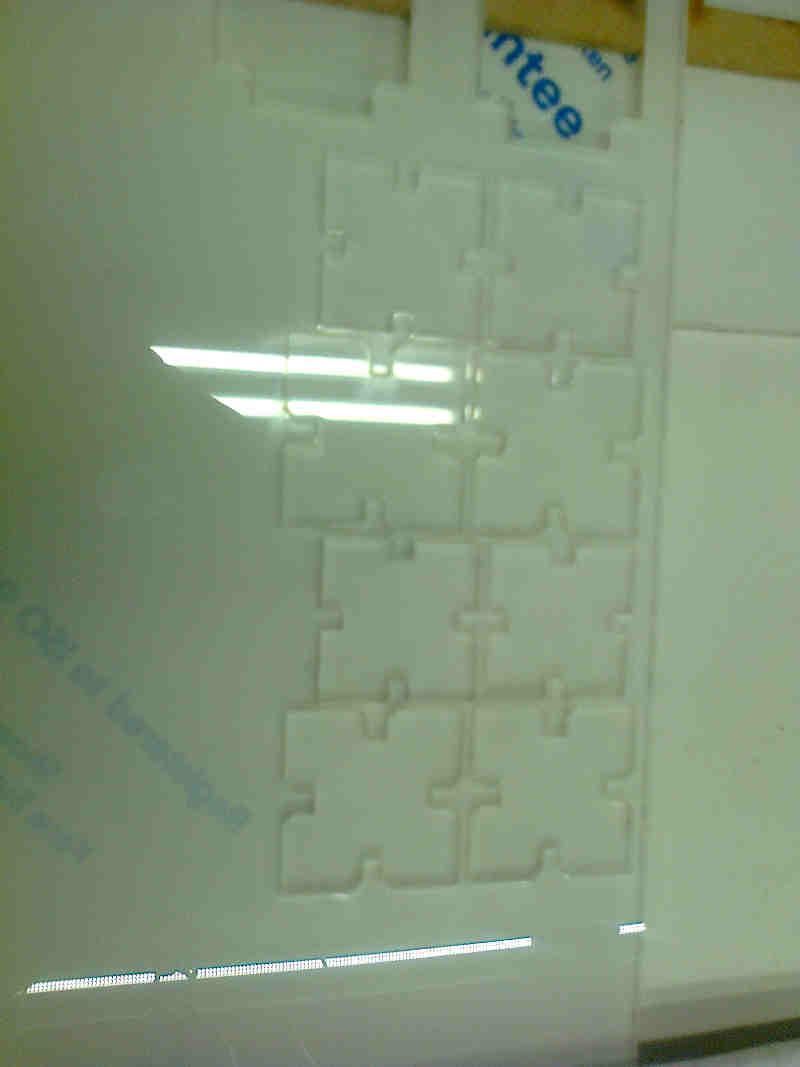 The workflow was forwarded to the cutter and the set was cut.
(6) We tested the constructed set to see if the Kerf calculations worked.
The chamfered cuttings were easier to assemble. However, chamfering does not affect on kerf. With soft materials, trying to push tight, cornered fits might also bend the material, causing a bit looser fit.
A better fit was achieved with MDF than on acrylic. There was also a noticeable difference in fit between slots cut in X and Y direction.
Relating dpi and Focus
Over in Bangor I ran a test to show how you can use a lower dip for speed and blur the line with de-focus for coverage.
600dpi results in a deep cut taking 51 seconds, 125dpi took 12 seconds but incomplete coverage.
When we de-focus the laser, we go from obvious lines to full coverage.
The Results we got.
Fitting of MDF worked as it should. Apparently, there was a difference between cutting between x and y directions. The fit of acrylic was too loose. The MDF value we used (0.0073 mm) was too low.
What did we learn?
We learned the laser cutter workflow from inkscape to products, safety issues and some important parameters, like kerf, power and frequency. We learned that making a working design probably involves testing.