7. Electronics Design
Group: Max, Antero
Group assignment:
- Use the test equipment in your lab to observe the operation of a microcontroller circuit board (in minimum, check operating voltage on the board with multimeter or voltmeter and use oscilloscope to check noise of operating voltage and interpret a data signal)
- Document your work to the group work page and reflect on your individual page what you learned.
The Group Work
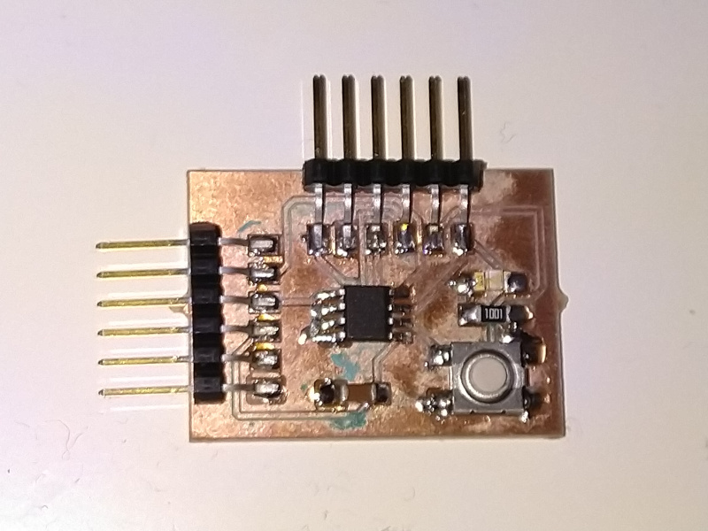
We used a basic microcontroller board build with approximately the same specifications as the one build in the individual part of week 7 assignment.
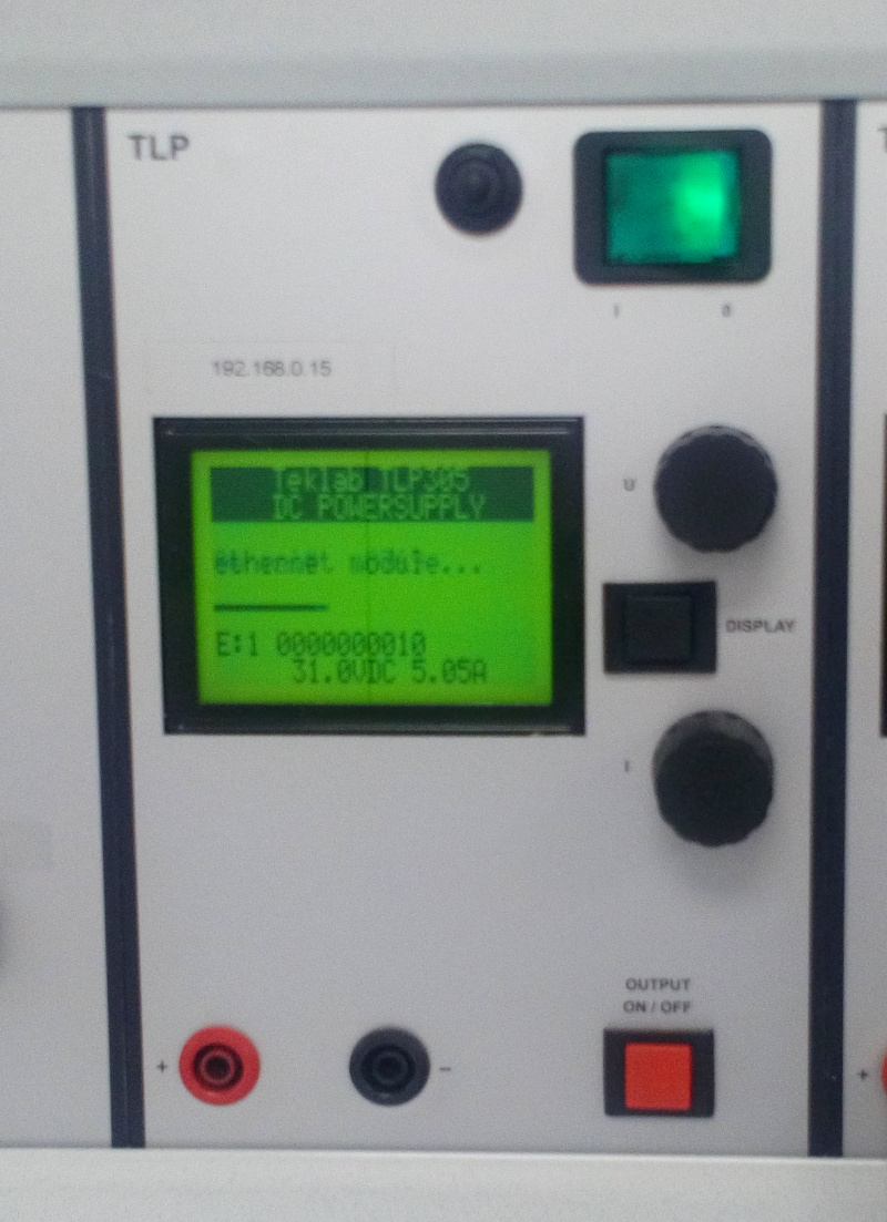
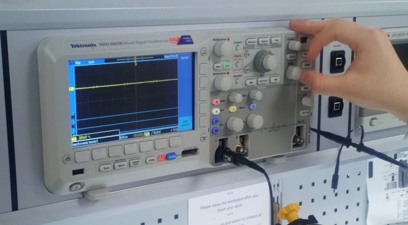
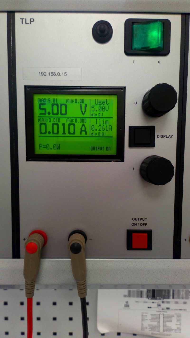
The equipment we used were TEKLAB TLP305 Power supply, Tektronix MSO 2002B Mixed Signal Oscilloscope and Fluke 175 True RMS Multimeter.

Calculating the power and energy consumption of the device.
We connected the power supply to the board, connected second cable for the pins connected to the output pin of the UART in the AtTiny412 microcontroller and adjusted the power supply voltage to 5 V.
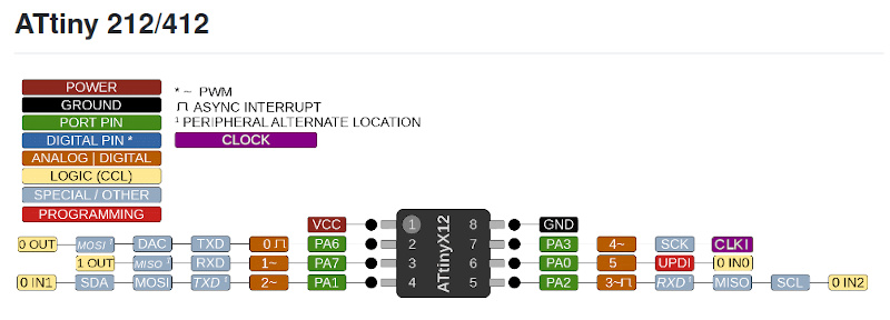
The pin used for measuring UART transmit data (TXD pin) was found from the following chart found from https://github.com/SpenceKonde/megaTinyCore/blob/master/megaavr/extras/ATtiny_x12.md.
The current consumption of the device, measured directly by the TEKLAB TLP305 power supply is 11 mA. This corresponds to 55mW power consumption at 5.00 V operating voltage. The energy consumption of a device, mentioned as an example of a feature we can measure from the device, can be calculated by multiplying the power consumption of the device by operating time. In one hour the device would consume 55mWh of energy.
Checking the noise of the operating voltage
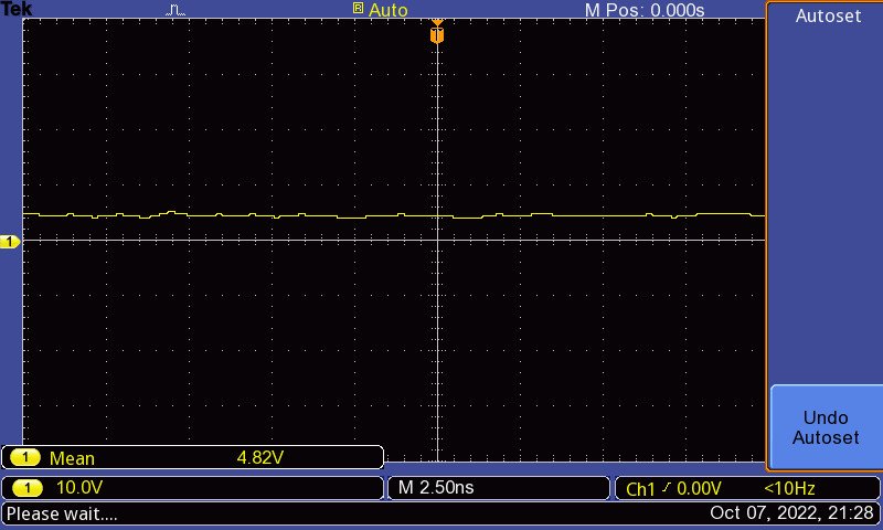
The noise of the operating voltage was observed with the Tektronix MSO 2002B oscilloscope. Note the different voltage measured at the time of measurement. It can be see, that the line in the oscilloscope is not flat. The power source is of good quality but the operating voltage still has some ripple in it.
Interpreting a data signal.
We made a program printing "Hello World" on repeat to the UART. The process of programming an arduino is described in "Embedded Programming" week.
The program we used is shown below.
void setup(){
  Serial.begin(9600);
}

void loop(){
  Serial.print("Hello World");
}
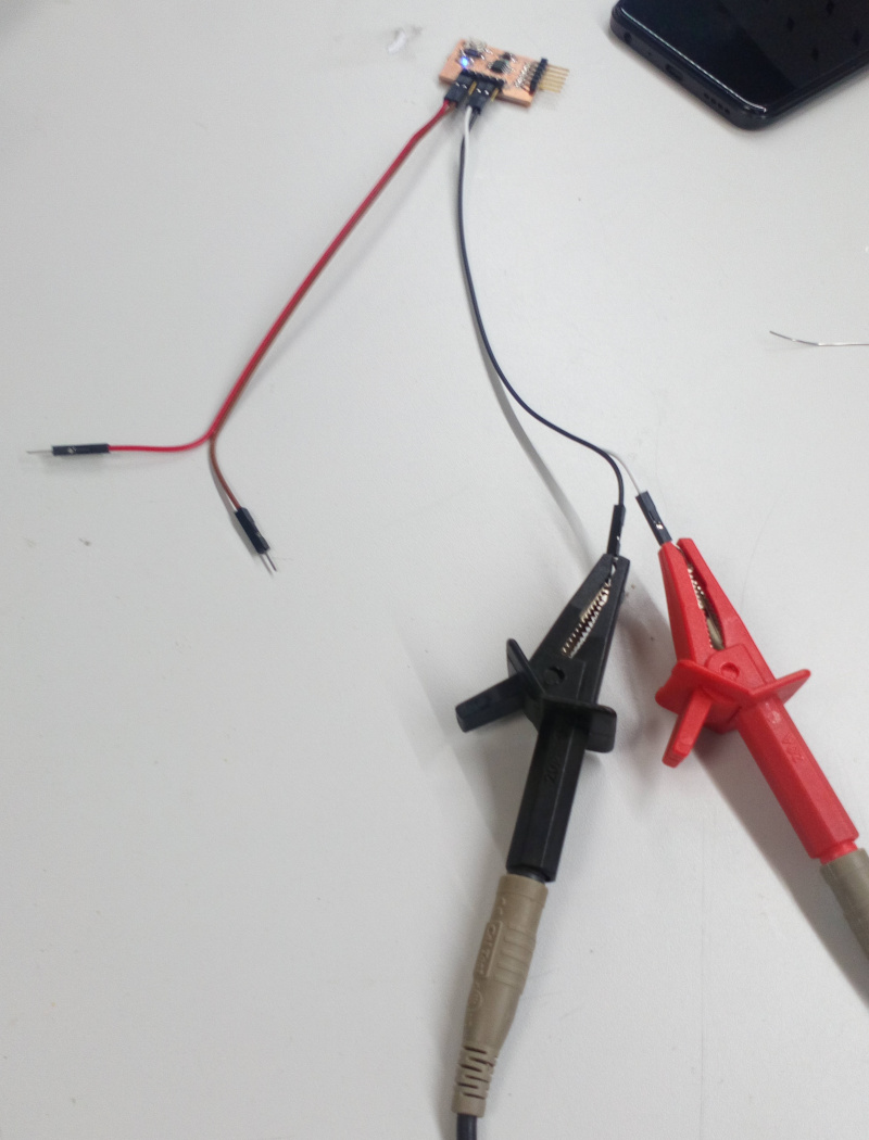
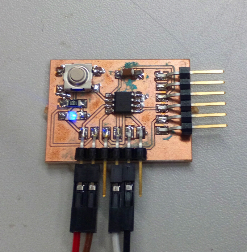
The connections of the cables in the board are displayed below.
We observed the UART output in MSO 2002B display. Picture of the oscilloscope snapshot of the data stream is shown below.
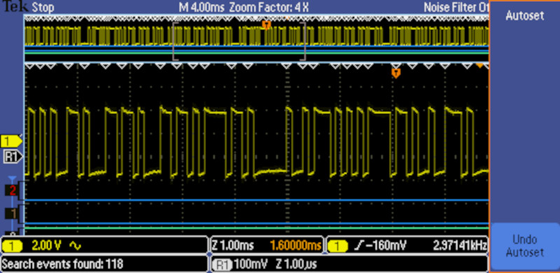
This is UART data and in this configuration high signal voltage seems to mean logical 1 in the bitsream.
UART sends the LSB first. There are start and stop bits included in the ends sequence. One 8 bit character is sent as 10 bit sequence. Example of a bitstream dervied from the display are shown below
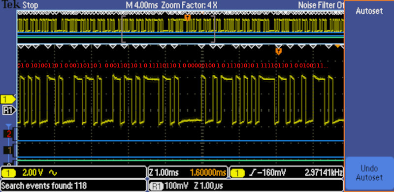
It is often difficult to find the beginning of the frame in the serial data sequence.
Based on the repeating stop/start bits and the location of the repeating letter L in heLLo WorLd, we decoded
............01
0101001101 ASCII e, bits in reverse order
0001101101 ASCII l, bits in reverse order
0001101101 ASCII l, bits in reverse order
0111101101 ASCII o, bits in reverse order
0000001001 ASCII space, bits in reverse order
0111010101 ASCII w, bits in reverse order
011110110'1* ASCII o, bits in reverse order
0010011101 ASCII l, bits in reverse order
000...........
The start and stop bits are bolded in the 10 bit sequences above.
Conclusion
We used the test equipment in Fablab Oulu to observe the operation of a microcontroller circuit board. We checked the operating voltage (in minimum, check operating voltage on the board with multimeter or voltmeter and use oscilloscope to check noise of operating voltage and interpreted an UART data signal)