5. Electronics production
This week we need to select a programmer, manufacture it and demonstrate that it works.
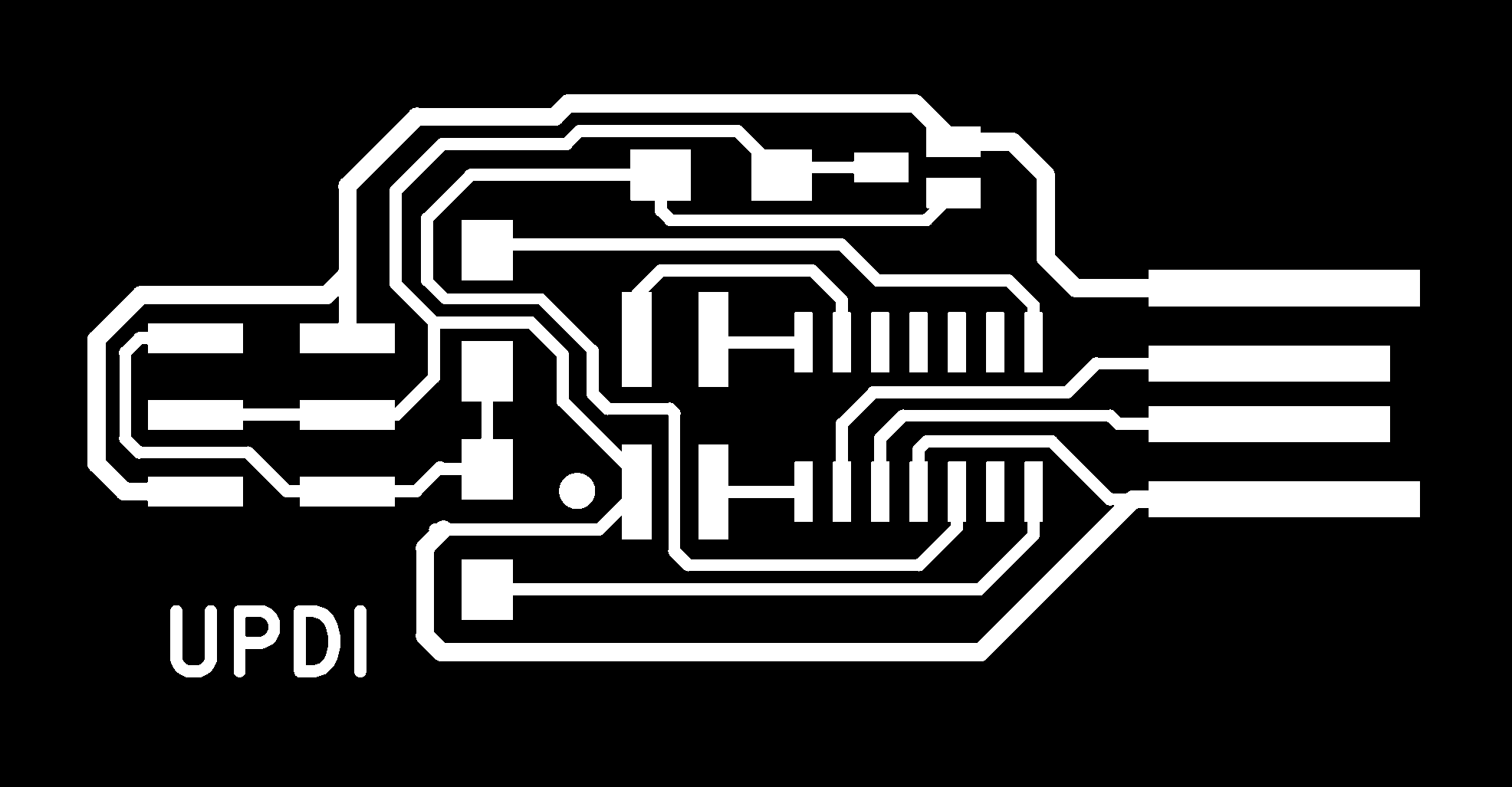
We now have a curated collection to pick from. The summary page of programmers gives us many options. Our target micros are the ATTINY412 and the ATTINY16x4, for which we need a UPDI programmer. We could make a simple FTDI adapter with a single resistor on it, but that would defeat the purpose of the week a bit. So from the list we’ve selected the UPDI D11C programmer based in the SAMD11 processor.
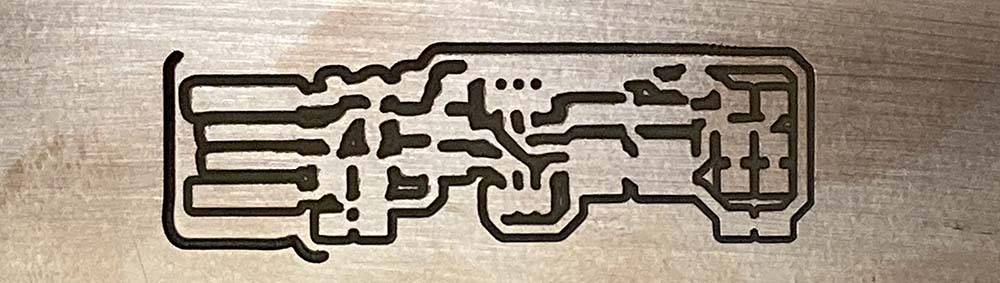
The following images were downloaded from the repository and used to produce the PCB:


Out of sequence
This was the week in the ordinary running of the course that I felt the impact of COVID. Not getting Electronics Production done till later, had a knock on effect in many aspects, throwing quite a few things out of sequence. So in this week, Electronics Design and the Programming week, you’ll notice that elements developed later have been fed back as evidence into earlier weeks.
Bootstrapping, chicken and egg problem…
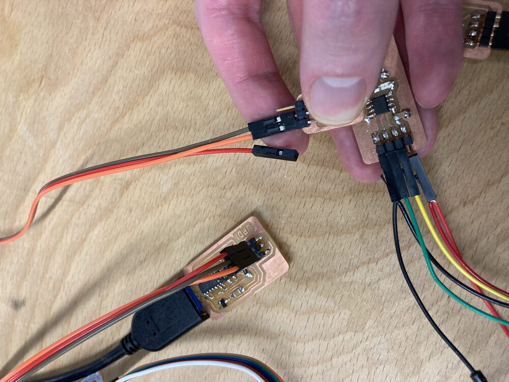
The selected UPDI D11C needs a SWD programmer to put the bootloader on. Without spending over 100 monetary units on an industrial tool, how do you program the microcontroller on the first programmer in the lab? After considering a load of avenues it seems that the best option is to get a friend to post you one. Fablab Oulu posted me a SWD D11C to bootstrap programmer manufacture in Fablab Pontio.
Group work
I covered similar ground here to the group work documented here.
and last year here
Milling a PCB
Understanding the process of milling PCBs. I first had a go at bootstrapping this process in the during the 21’ cycle. Issues that cropped up are detailed below. The tools are constantly evolving so in ‘22 I used modsproject with more success and with practice have bedded down the PCB manufacturing process.
To manufacture our PCBs we’ve all made use of the Roland SRM-20 mill. Preparing files with modsproject
Preparing .rml
The outputs from our EDA tools are all images, we need to convert them to tool paths for our chosen machine. Modsproject has a program for that.
First off open modsproject you’ll arrive at a nearly blank page with some terse instructions. Right click for a menu and follow the rabbit down:
programs > open program > machines … Roland … SRM-20 mill … PCB CBA
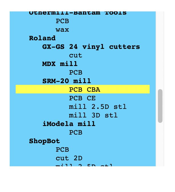
This is the program that you open:
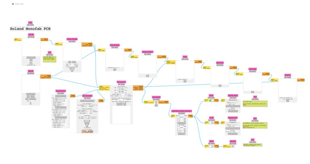
Zoom in, right and down a bit to configure your outputs. Use your mouse scroll wheel. Switch off ‘Websocket Device’, switch on ‘save file’. Set origin to all 0.
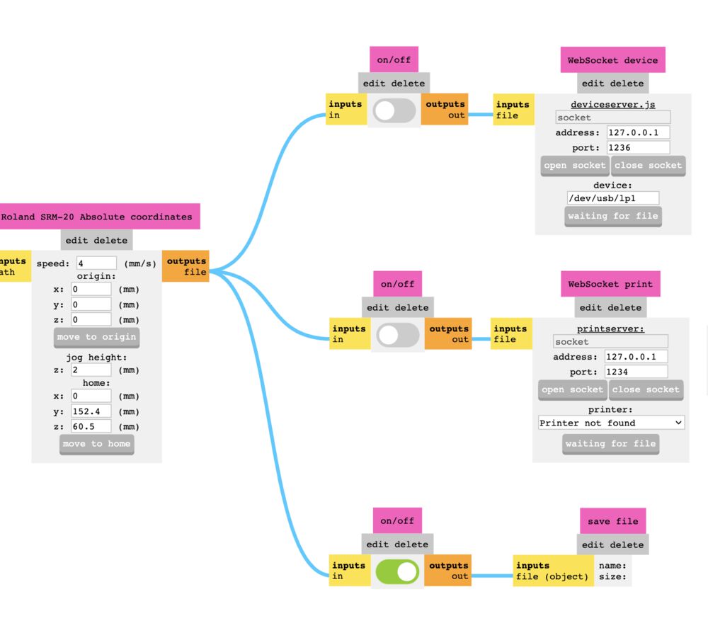
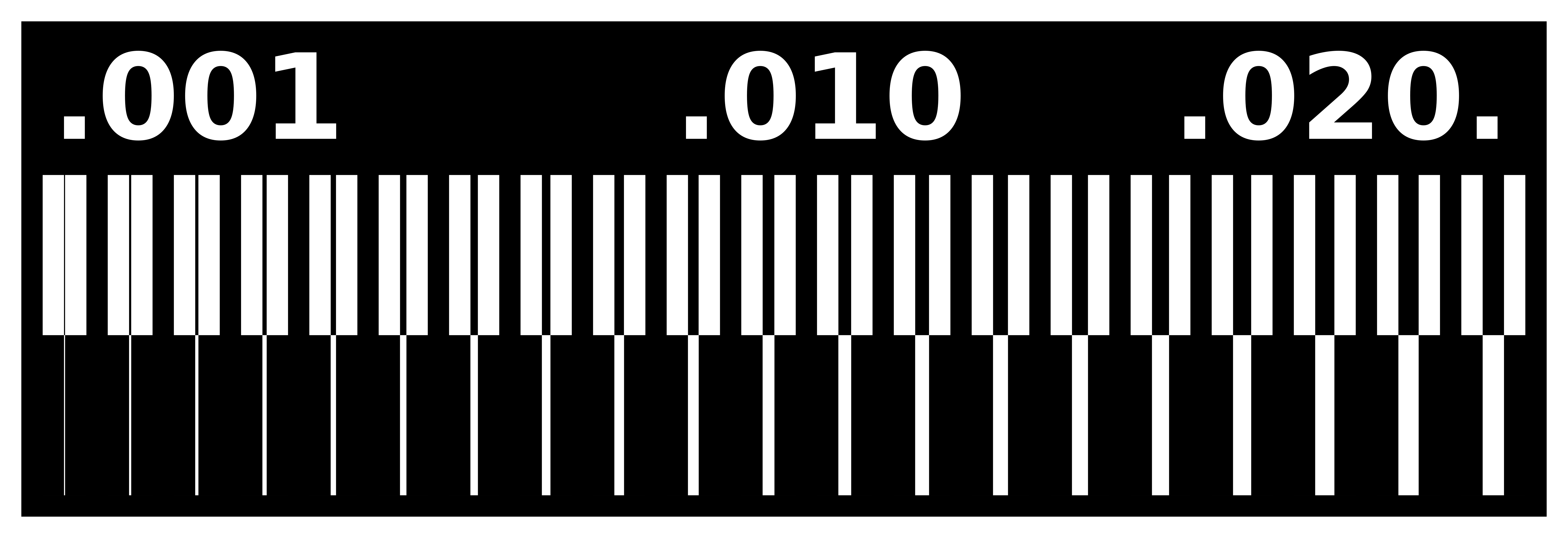
Select the image you want to process, in this case a test piece, image included separately
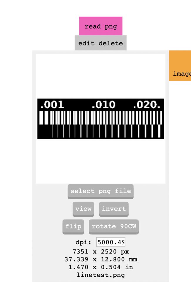
It should be noted that the algorithms generating the tool paths are looking to preserve the white areas. Sometimes your artwork is inverted, with black tracks. Use the invert button here to sort that out.
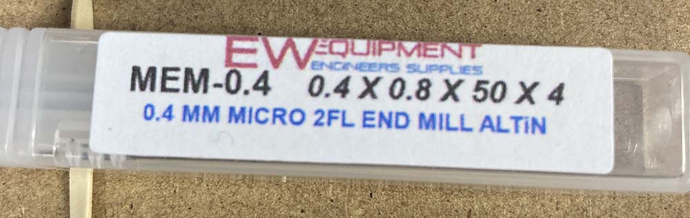
Next setup the tool for the process you need related to the image. We default to a 0.4mm end-mill for our tracks. After running a number of boards through we’ve found that a depth of 0.12mm works with our supply of FR1 boards, without breaking tools. For some of the work we’ve done we’ve used a 0.8mm tool to do the outlines, with default settings for depths. This allows us to drill for the through hole parts as well as cut the outline. For those jobs that are solely SMT we’ve used a 1mm end-mill. The boxes on the left here have buttons that allow you to auto fill the last box on the right, some setting can be tweaked, eg from an imperial mess to a nice round metric.
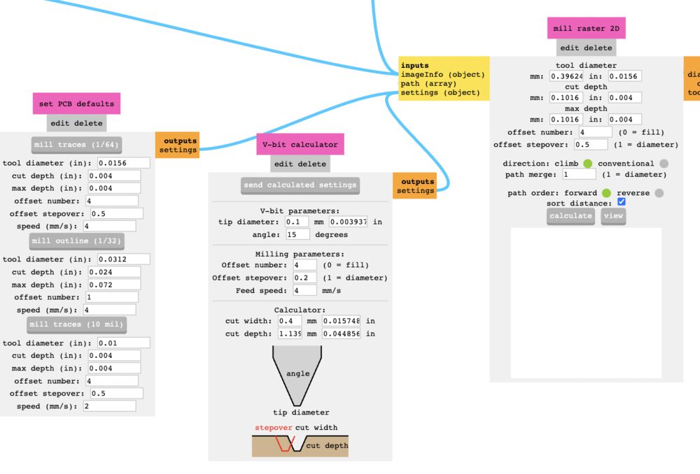
A closer look at the filled in boxes
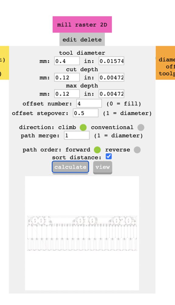
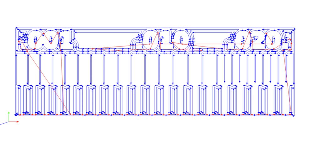
Once you have a tool setup hit calculate, and if the preview looks good save the resulting .rml file.
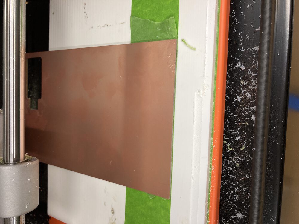
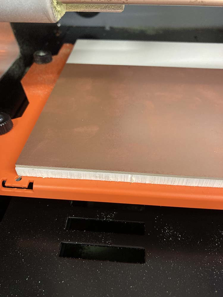
Prepare the bed, add a PCB blank
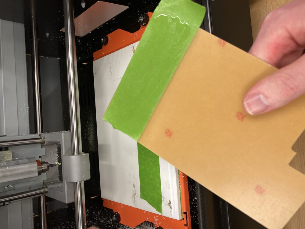
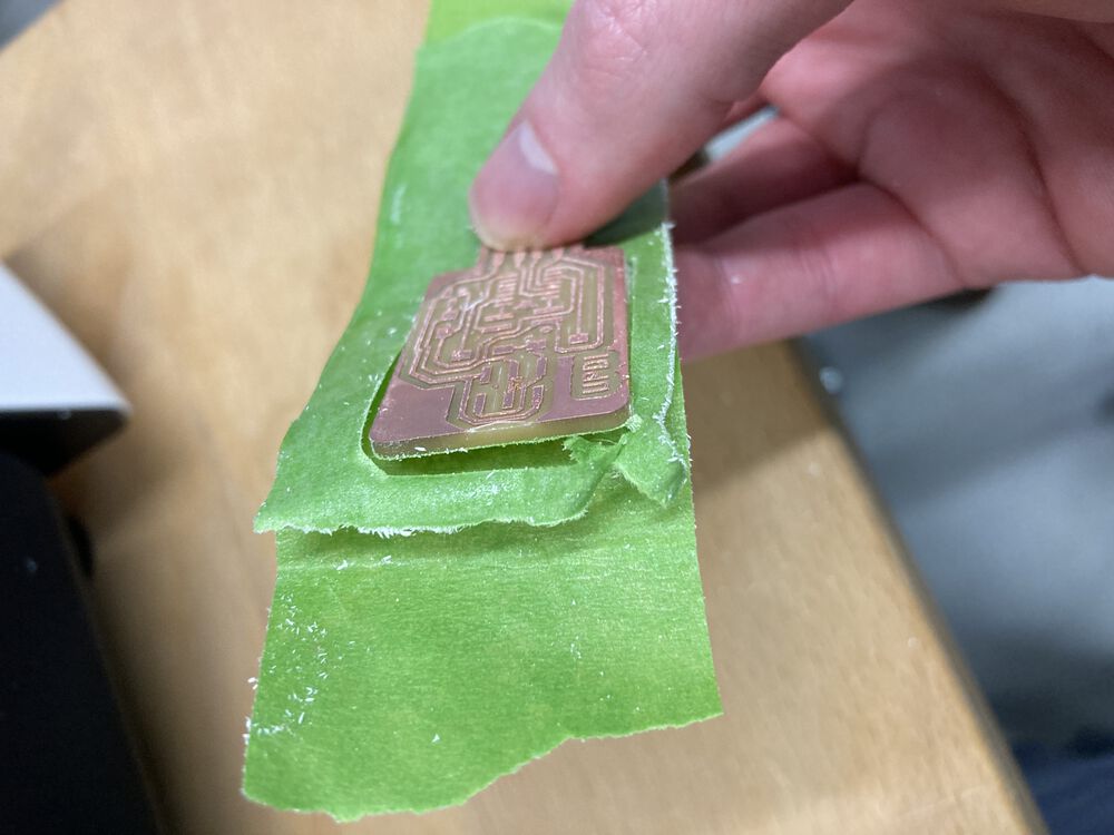
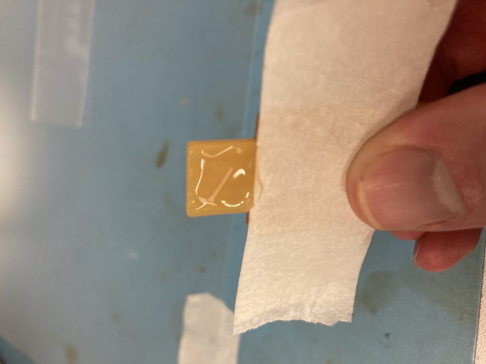
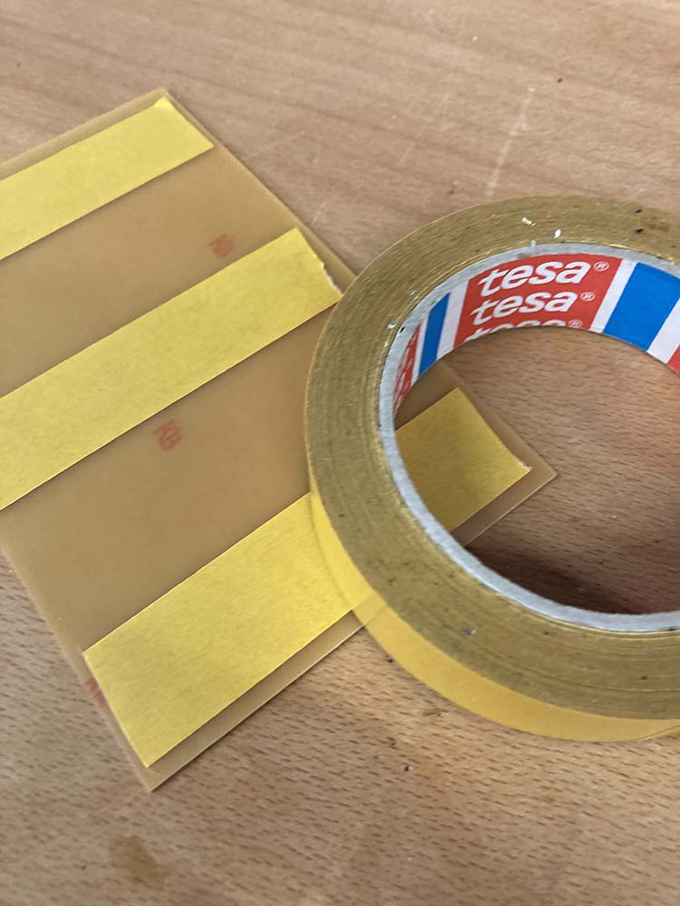
You can see in the appendix below that last year we were using double sided tape to put things down onto the bed of the machine, this material is quite prone to failure, makes a mess of the boards and is generally a pain to use. We’ve since moved to use the masking tape and super glue trick. Cover both mating surfaces with tape, add super glue to one side and activator to the other and press together. In the images here we can see the trick being used to add the spoil board to the machine bed, then adding a blank FR1 to the spoil board.
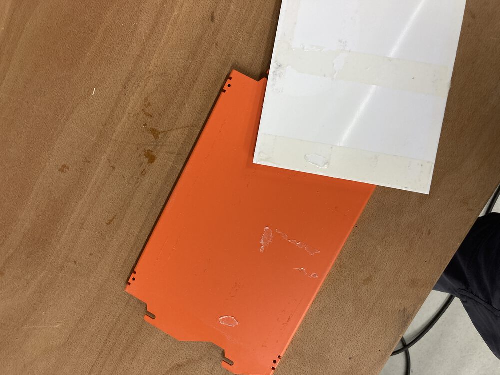
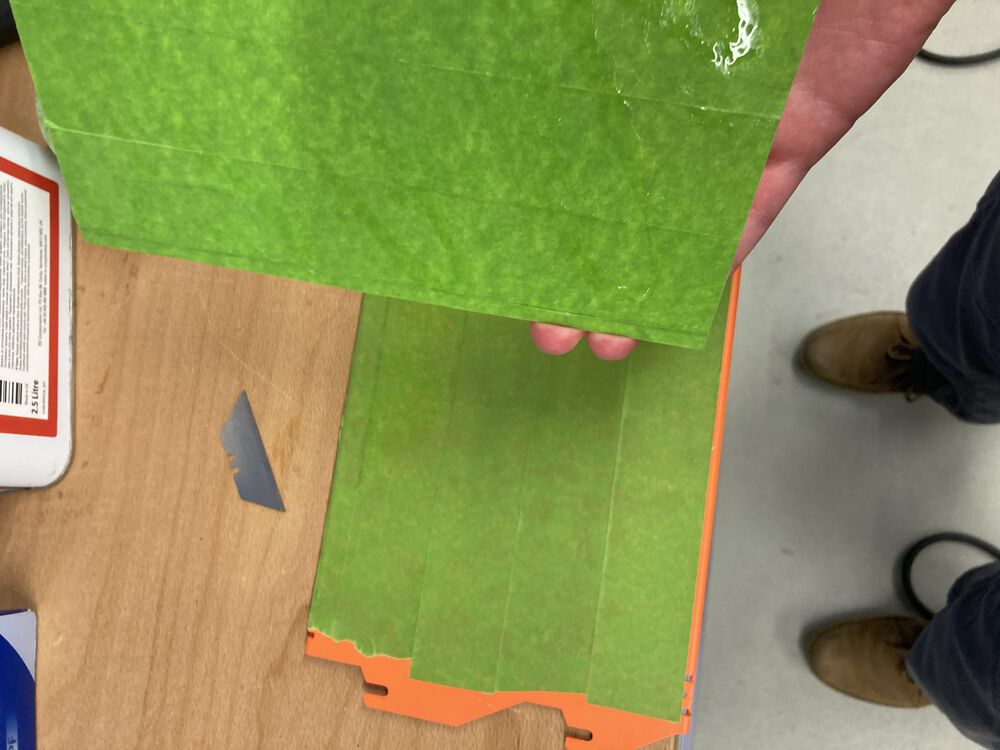
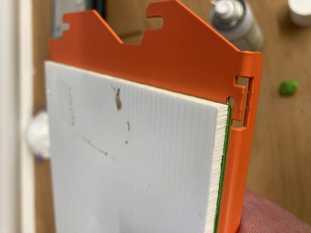
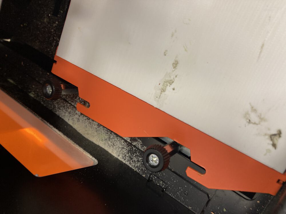
Note that the machine bed slides of the pillars, you don’t need to completely remove the retaining screws.
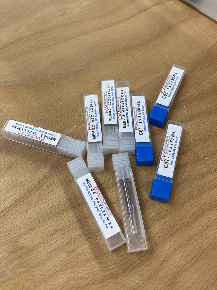
Install a tool
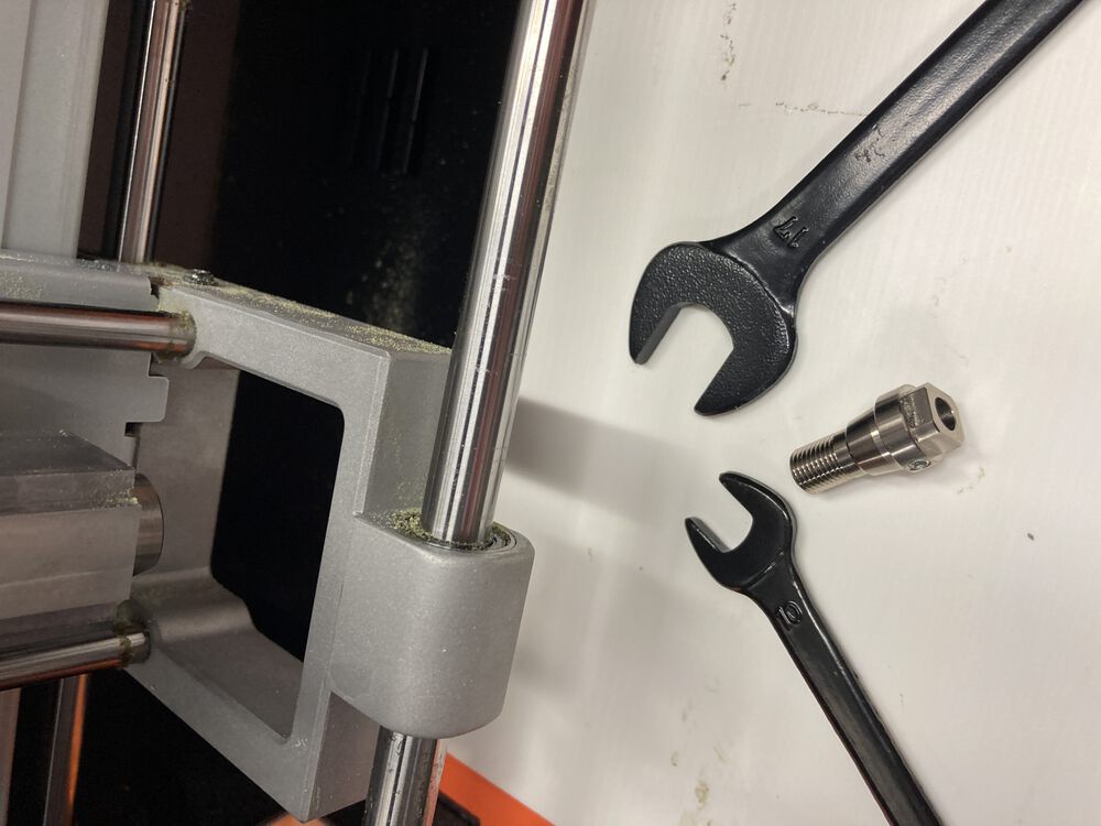
We have some old stock tools on an imperial shank that fit with an adapter into the 6mm collet and our newer tools are all 4mm shank. See the problems below if you mismatch your tools and collets, the resulting run out is detrimental to you PCB making. To instal a collet appropriate to your tooling you’ll need the spanners supplied with the machine. Screw the collet into the spindle until it stops then tighten one eighth of a turn. No tighter, or you’ll wreck your threads.
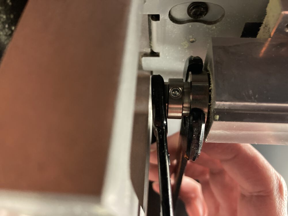

Once you hae a collet in place you can put in a tool and using an allan key tighten the grub screw finger tight.
Setting origins
To control the mill we need to open: VPanel for SRM-20
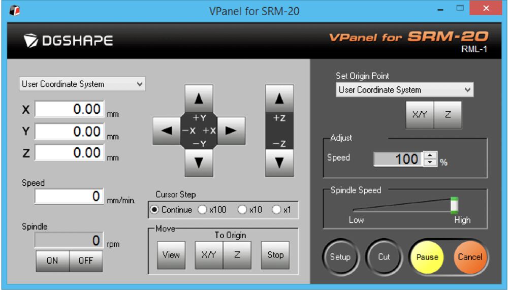
The first job is to set the origin of the tool:
- Using the X, Y plus and minus buttons move the tool to the front (closer to you) left of the board, a few millimetres inside the corner.
- Hit the X/Y button to set the x y origin.
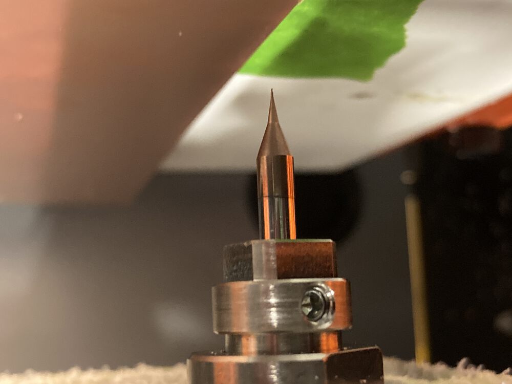
- Using the plus and minus Z buttons move the tool within two or three mm of the surface.
- loosen the grub screw holding the tool and let it drop to the surface, re-tighten the grub screw.
- Use the Z button to zero the tool offset.
- before anything else raise the tool off the surface.
Send code
Behind the Setup button check that the ‘Command Set’ is set to ‘RML-1/NC Code’.
Use the Cut button to access a dialogue to send our gcode to the machine.
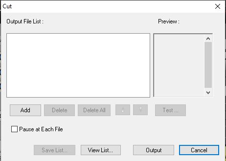
- Use the Delete All button to remove any previous work.
- Use the add button and find the .rml file we produced using modsproject
- Hit Output to run the code.
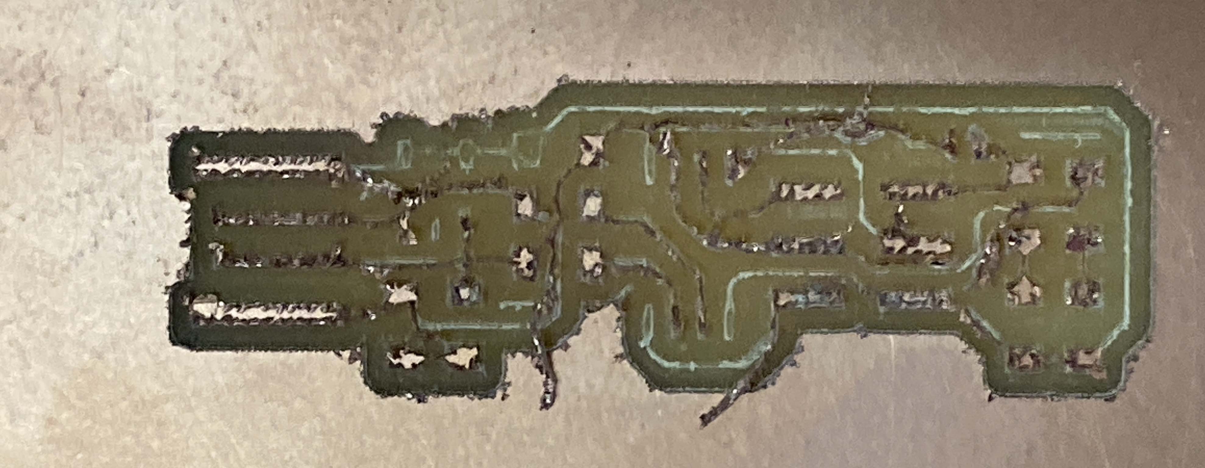
Test cut result
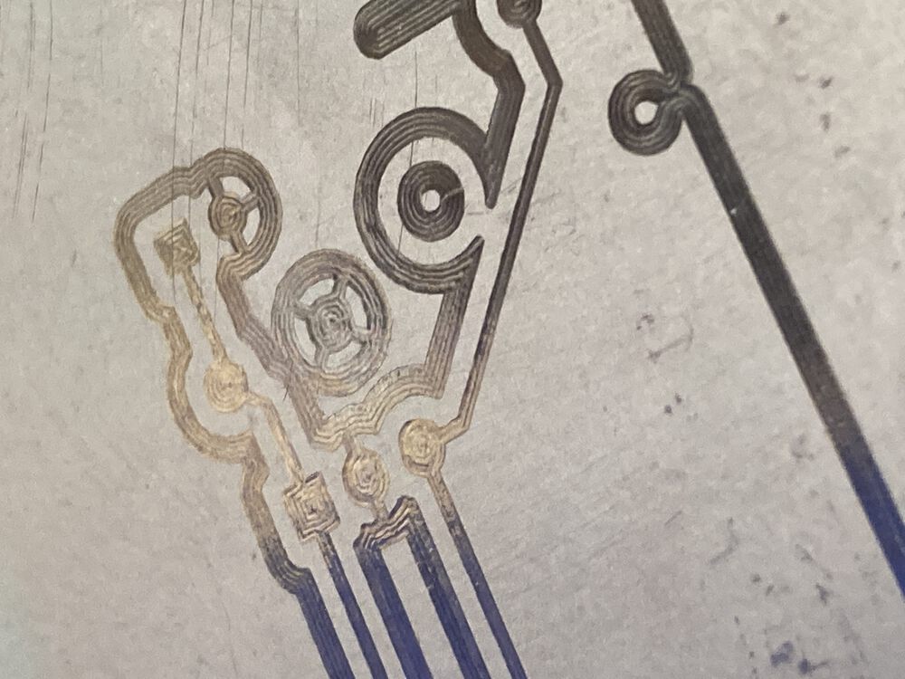
The illustrated test example was run twice, once with a worn tool and once with a sharper tool
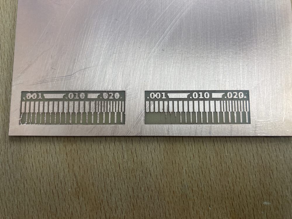
We can see that a dull tool can leave a lot of burr along the edges of the tracks.
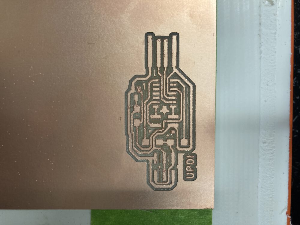
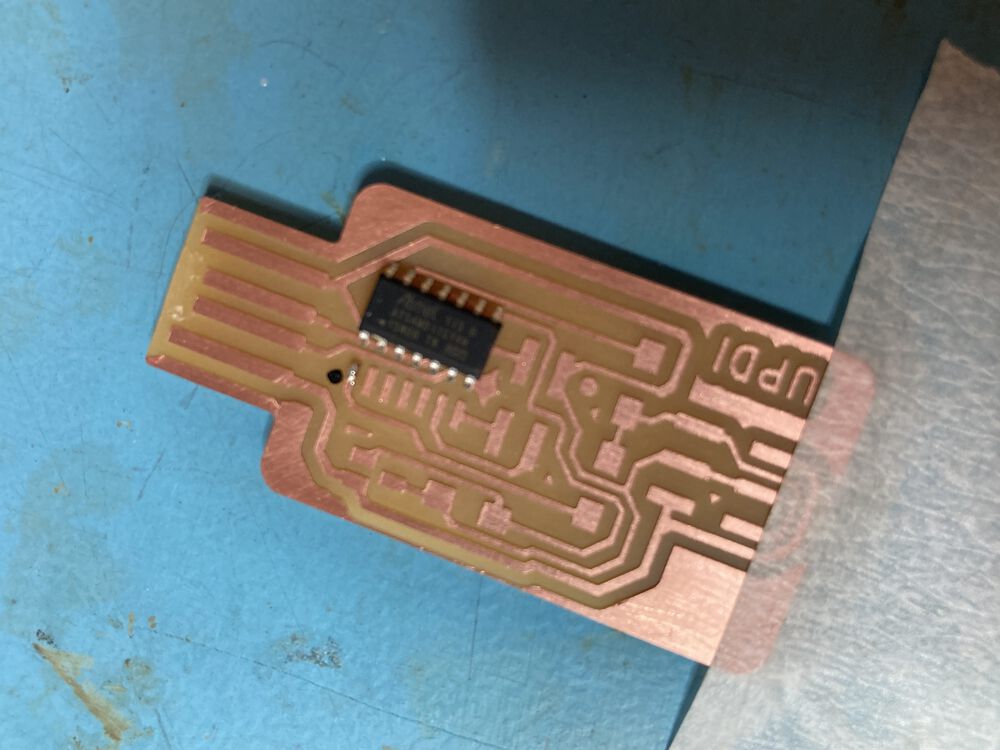
Tracks and outlines
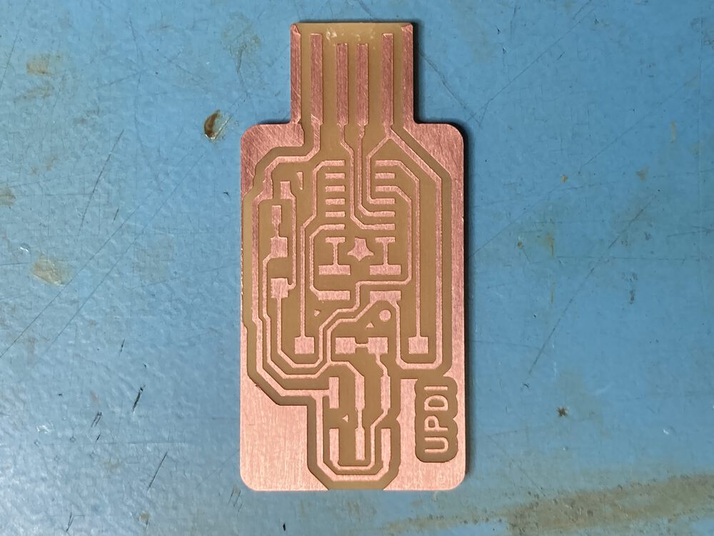
For this weeks task we are milling out a PCB for the UPDI D11C programmer. Using the images at the head of the page and modsproject we produced two .rml files. One setup to cut the isolation of the tracks with a 0.4mm end-mill, the second to cut the board outline with a 1mm tool.
We setup with the 0.4mm tool as described above and run the code for the tracks.
Tool change
For the outlines we need to change the tool. The procedure is similar except that we leave the X/Y origin as it is, and only zero the Z tool offset.
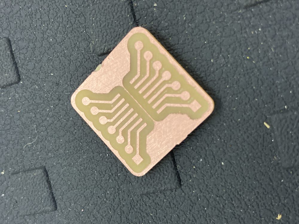
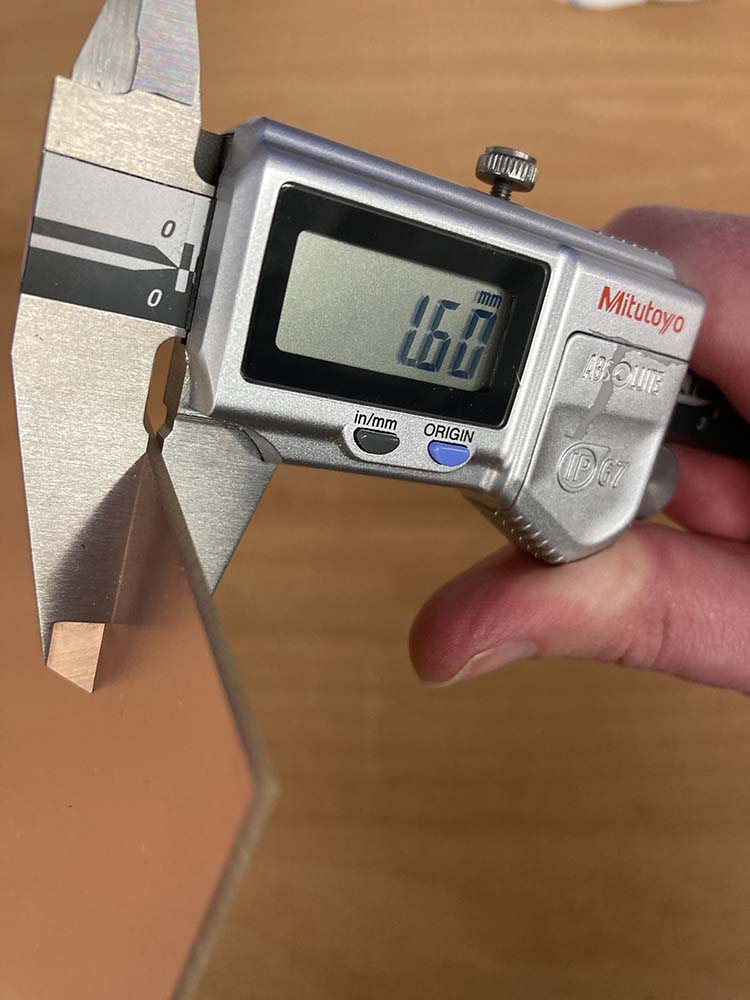
Here we see the board during manufacture, after the tracks were milled, after some de-burring, ater the outline was cut and after removal from the bed. In that last image we can see that the depths are pretty spot on, cutting tape but not into the spoil board.
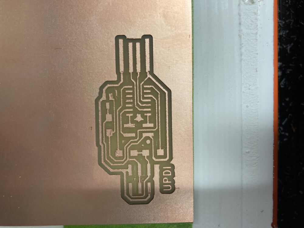
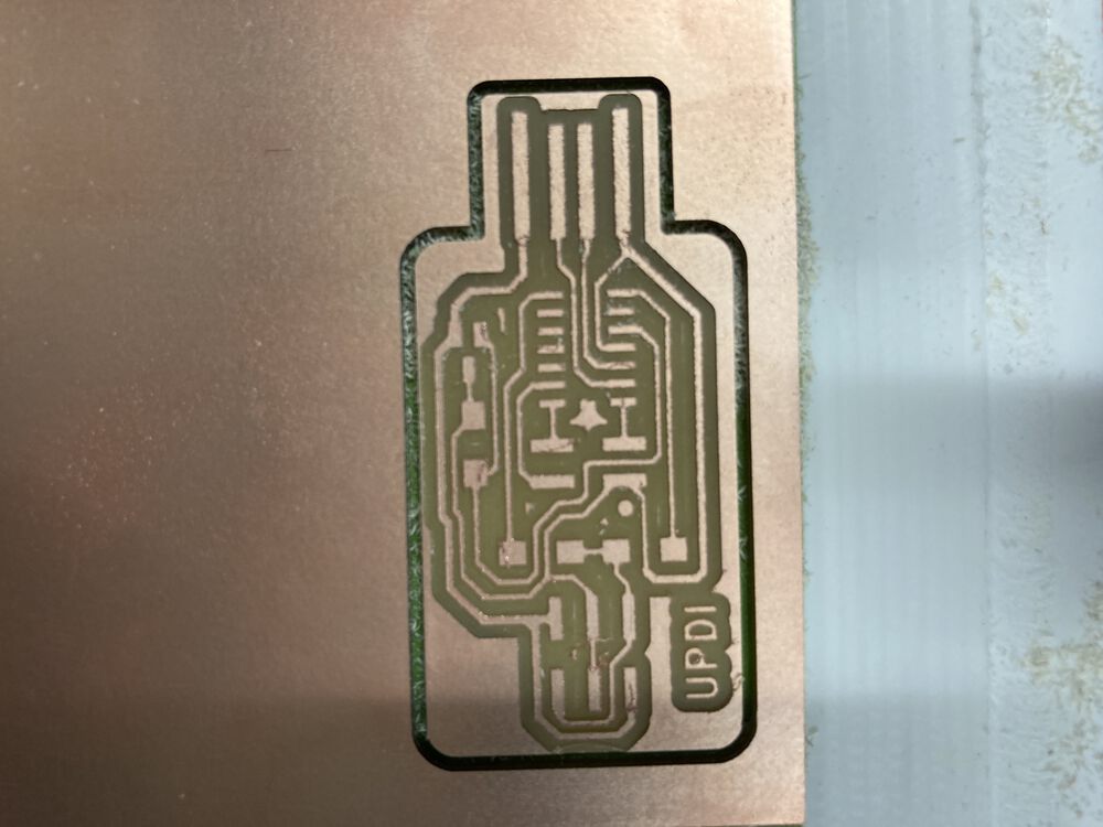
After cleaning we have a board ready to ‘stuff’
Potential issues
It doesn’t always go right
Not cutting through
If your FR1 is not very level it’s possible that you’ll end up not cutting through the copper in some region of your board. The depth of cut is a fraction of a mm. If you get shiny copper instead of dust:
Use the following to recover.
- Allow the cutting job to finish.
- move the tool so that it’s over the shiny/not cut tracks.
- re zero the tool offset in Z.
- run the job again
Breaking tools
If you break a tool, they have a finite lifetime, put in another and go again from zeroing the tool Z offset. If you break another check you feed rate.
Tracks and outlines don’t line up
Make sure your source images are the same size and well aligned. If you were using Inkscape to manipulate the images before use, make sure you exported the ‘page’ for both and not a ‘selection’ for one by accident.
Soldering
By the usual method of putting solder down on one pad, introduce the part to a re-melted solder, let it set then solder up all the other pads. Didn’t take many images of the process. We have the first pad, the parts on then the parts on with the excess copper from the USB connector removed.
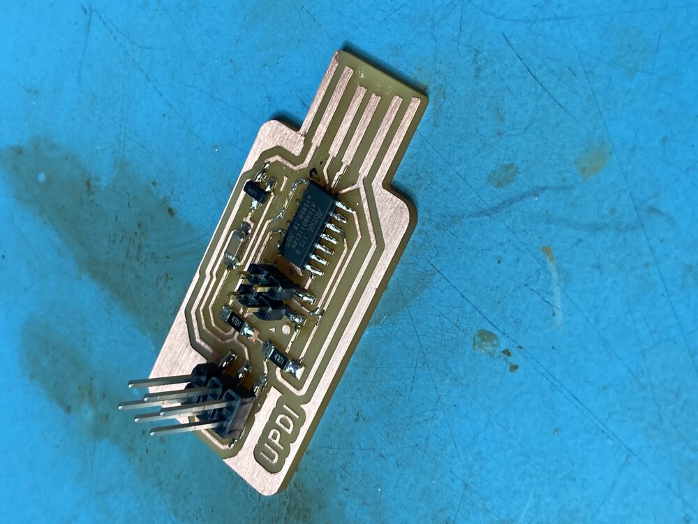
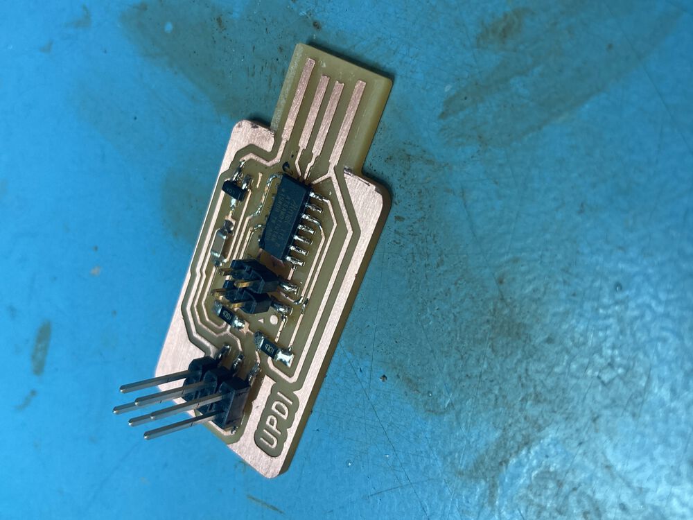
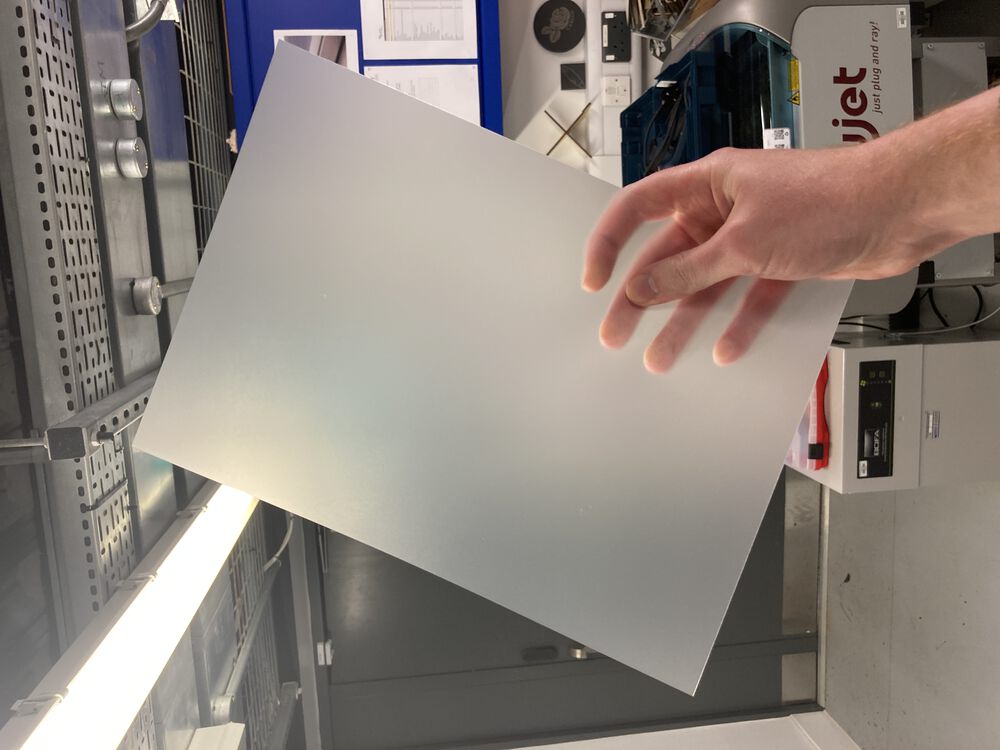
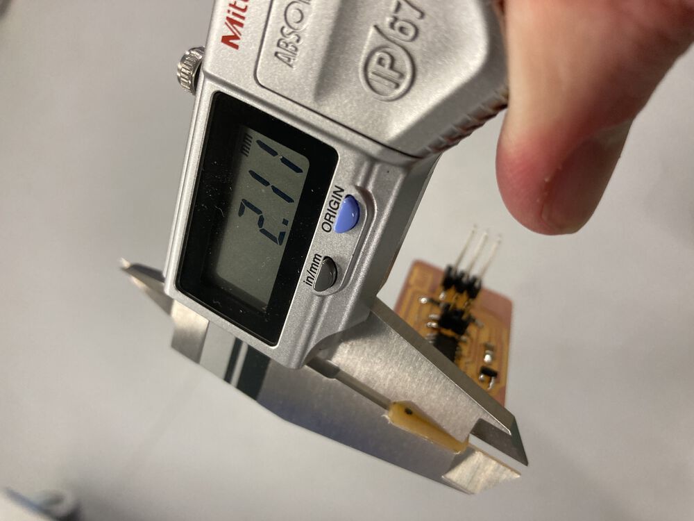
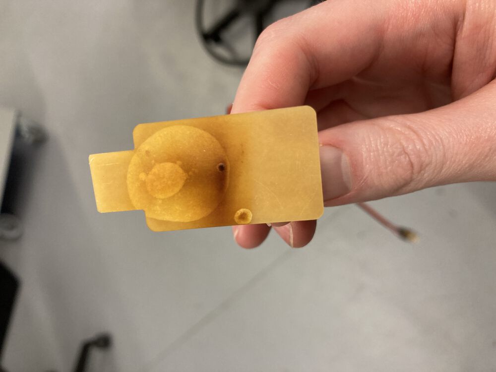
Making the board a bit thicker. Found some plastic that we use to put covers onto spiral bound documents. The back of the USB connector is masked and super glued, put down on the edge of the plastic sheet and trimmed to size.
The finished part is a little thick but not far off.
Programming
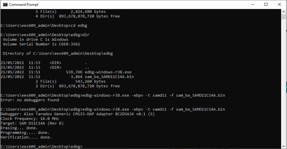
The programmer repository has instructions for programming the programmer. It’s a two step process of introducing a bootloader with edbg then adding the functionality by downloading an Arduino sketch to the device.
I followed the instructions for installing edbg carefully, but couldn’t get the bootloader onto the device.
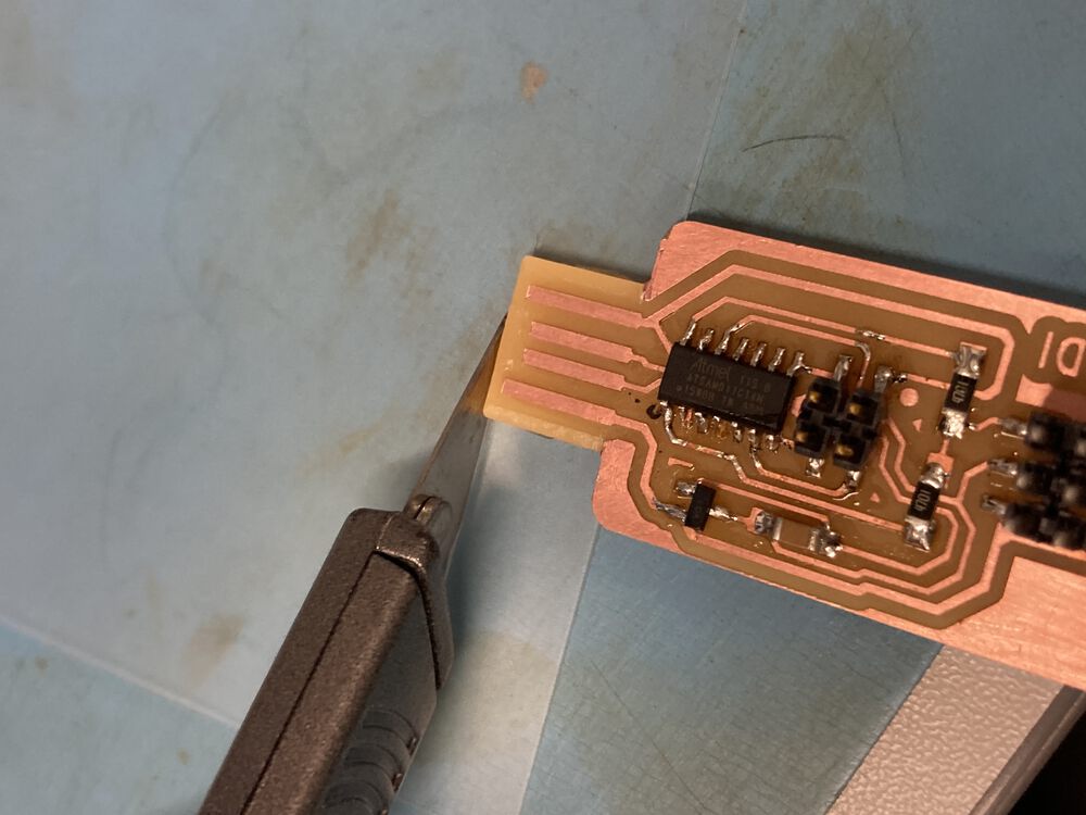
I had a little trouble soldering on the mirco, pins got bridged and it took possibly too much heat to separate them again. I really miss solder resist on these boards.
Thinking I may have cooked the micro I decided to replace it.
Re-work
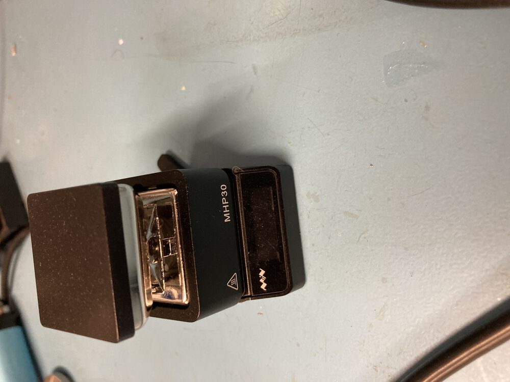
First attempt was with a mini hotplate, the result was burning off the plastic I used to thicken the board at the connector and popping noises as the PCB de-laminated, but no de-soldering.
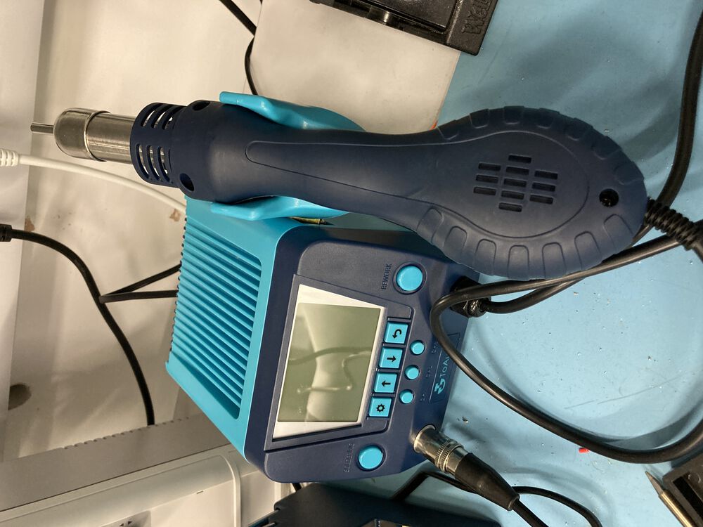
Using hot air worked better, and I was able to clean up and put a new processor on the board. This time without bridging or excessive heat.
Programming successfully
I had the same result trying to program the device. Coming to the conclusion the it may not be the device. It could be that I’ve not got my M1 Mac set up correctly.
Jani suggested I try a Windows box:
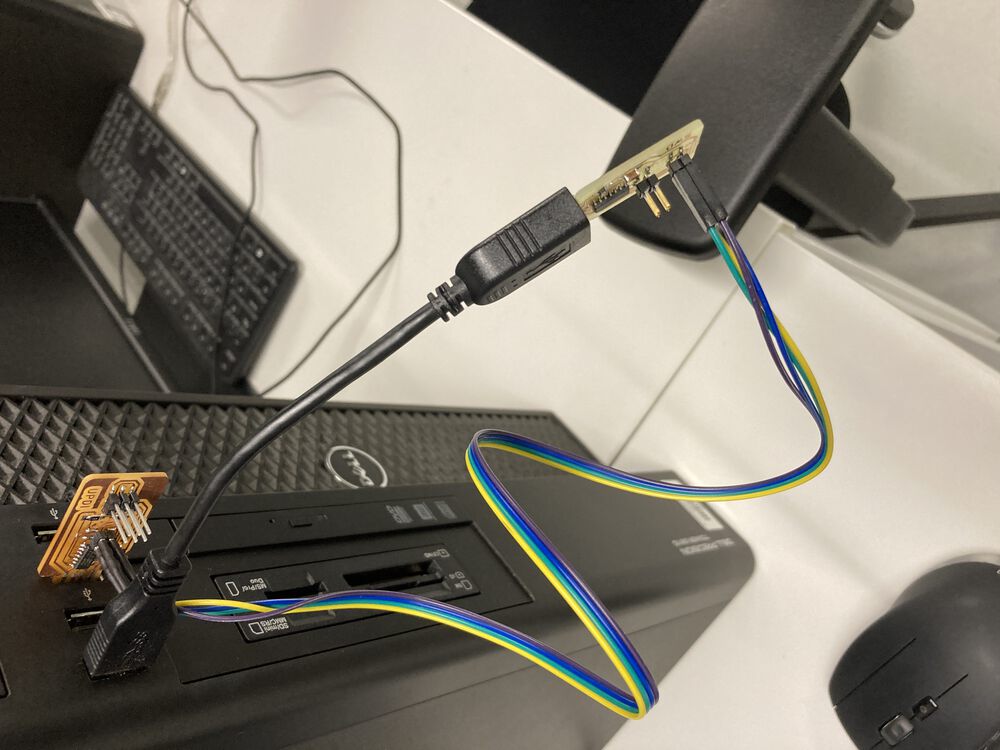
it just worked.
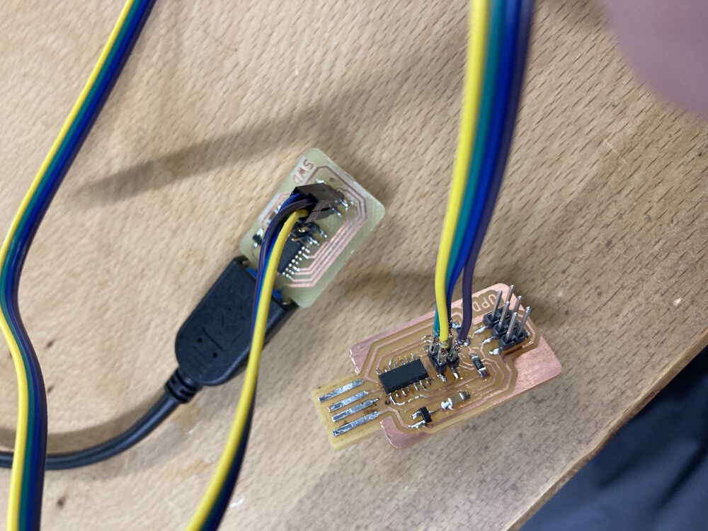
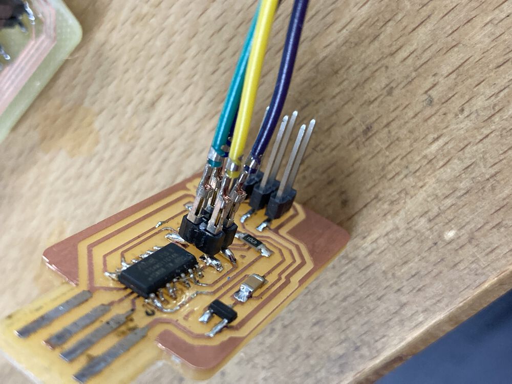
One Arduino sketch later and we have a working programmer.
Using the programmer
You can see examples of microcontrollers programmed by this device in later weeks assignments including Embedded Programming
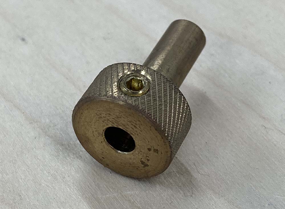
In the image here the board is the echo board that we will be making in the future for Electronics Design. It’s powered by an FTDI cable and programmed with the aid of a little pogo pin adapter.
Always ask for help… it may not be you.
I had a few miss-fires in ‘21 and making PCBs was one of them. I seemed to be plagued with IT gremlins that have since been resolved. If you come across an issue, it’s worth learning how to ask good questions on forums. Make as complete a question as you can, put your problem in context so that the people responding have a chance to help without a round trip asking you questions in return. Two issues came up for me last year whilst I was trying to mill PCBs.
Mods is under active development.
During the ‘21 cycle, circumstances meant I was delayed in making a second effort at producing PCBs. I came back to mods a few weeks after most students had milled and stuffed PCBs.
I thought I was going crazy, I was doing exactly as I’d done before with success, only getting weird behaviours from the machine. I thought there must have been changes due to a driver update or similar and went to test some alternative workflows, see FlatCAM issue below. I could have saved a lot of time and effort if I had asked for some help straight away:
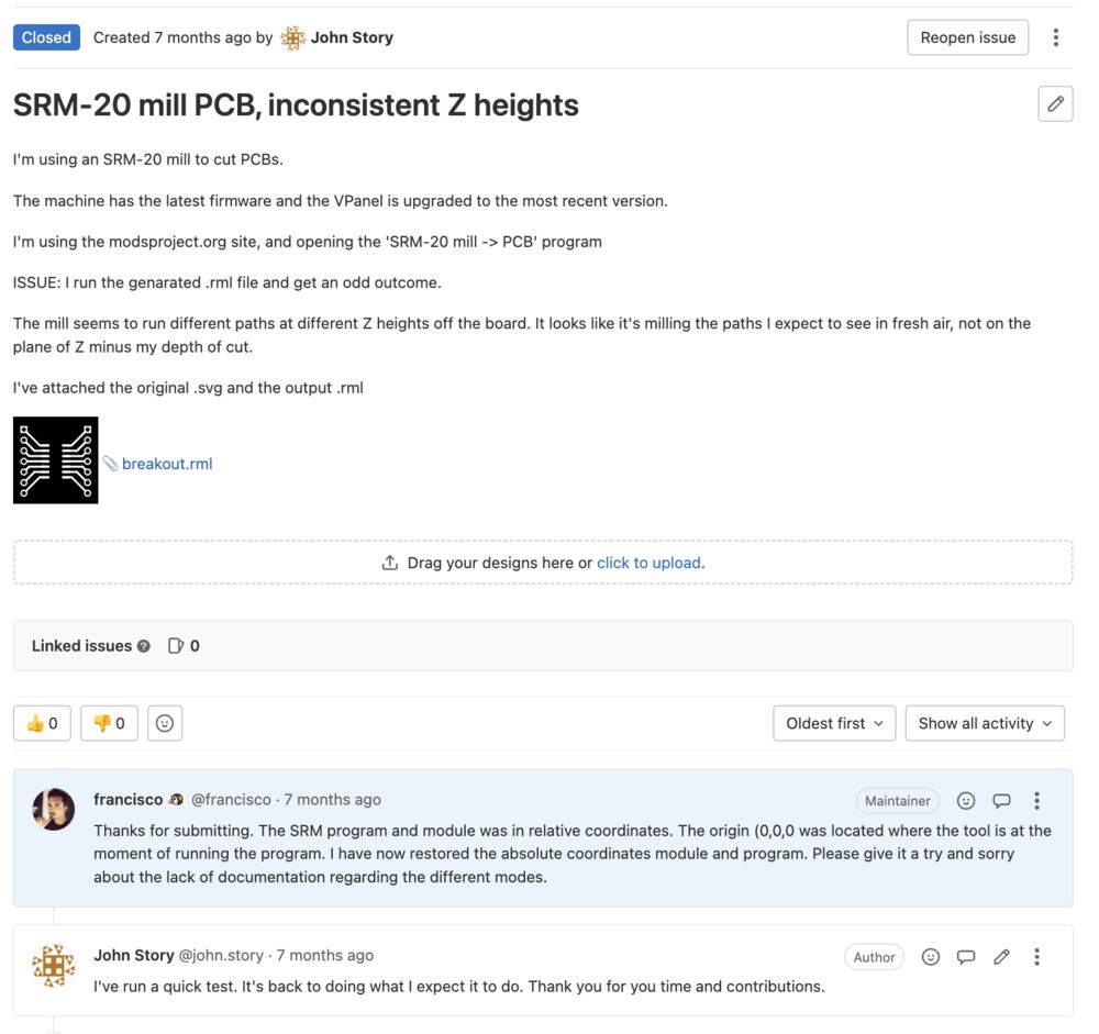
Turns out the live mods was undergoing some development. The issue was resolved very quickly once I asked for help.
FlatCAM, RML1 is not the same as other gcode.
During the time I was looking for solutions to the wacky mods behaviour I tried FlatCAM. Only to find another wacky behaviour. This time I asked for help straight away. The next version of the software should be improved thank to the interaction with the developer.
As there was no imminent release of the software due, I came up with a workaround script to correct the output for the SRM 20.
import sys
import re

# first command line argument is the input file
inputFile = open(sys.argv[1], 'r')
# if a second argument is provided use it, else insert '_out' into the input file name
outputFile = open("_out.".join(sys.argv[1].split('.')) if len(sys.argv) < 3 else sys.argv[2], 'w')

lines = inputFile.readlines()
for l in lines:
    if re.search(r"^Z", l):
        numbers = re.findall(r"[+-]?\d*\.\d|0", l)
        results = [float(i)*2.5 for i in numbers]
        string = "Z%.1f,%.1f,%.1f;\n" % (results[0], results[1], results[2])
        outputFile.write(string)
    elif re.search(r"^\(", l):
        # cutting out the comments
        print 'Skipping:', l
    else:
        outputFile.write(l)

inputFile.close()
outputFile.close()
With that bit of python in hand I was milling with FlatCAM, with the mods reinstated to a working version I had two options for PCB CAM.
APPENDIX ( From 21’ Cycle )
This first effort we’ll have to call chapter 1. I have not completed the tasks so far, here’s what I learned.
In short, having levelled the bed we began to mill boards. They came out ragged, eventually diagnosed a mismatch between tool shank and collet adapter. One was 4mm the other 4.36mm. The resulting run-out meant that the boards could not be milled. We did find a matching 0.8mm tool and 3.17mm collet adapter which demonstrated that the mill and process works, but that tool was not fine enough to mill out the circuit.
To resolve the issue we’ve ordered a 4mm collet for the SRM-20. When it arrives we’ll repeat the exercise, should be here in time for electronics design week.
Chosen design
Attiny45 based programmer by Brian
Tools and Software
Roland SRM-20 - Fablab Pontio Small mill resources
V-Panel
Milling a PCB
Good batch of PCB stock, stuck with tape to the levelled bed.
 Carbide micro mills
 Ragged results
 A properly milled, but incorrect result
 The culpret
Programming
https://raw.githubusercontent.com/qbolsee/ArduinoCore-fab-sam/master/json/package_Fab_SAM_index.json
Past project
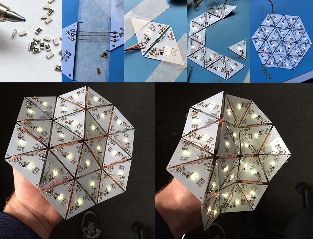
As evidence that I can solder, I’ve put in a past project. Using the ATTINY10 to create a custom serial chain of LED’s in a flexible panel.
Attiny, programmed in assembler in Atmel Studio, chain driven by a custom Arduino Library, sinlge wire protocol with timing to fit the capabilities of the attiny10.