6. 3D Scanning and Printing
Summary
This week we were exploring 3D scanning and printing. In particular testing the printer with some of the examples provided and designing an object that may not be produced by other means.
Tools and Software
Ultimaker 2+ - Pontio fabalab resources 3D Sense Artec Spider (revised device)
FreeCAD Meshmixer Cura Artec Studio 12
Files
Fidget Robot Monster (Source)- fidget_robot.FCStd
Fidget Robot Monster (printable) - fidget_robot.stl
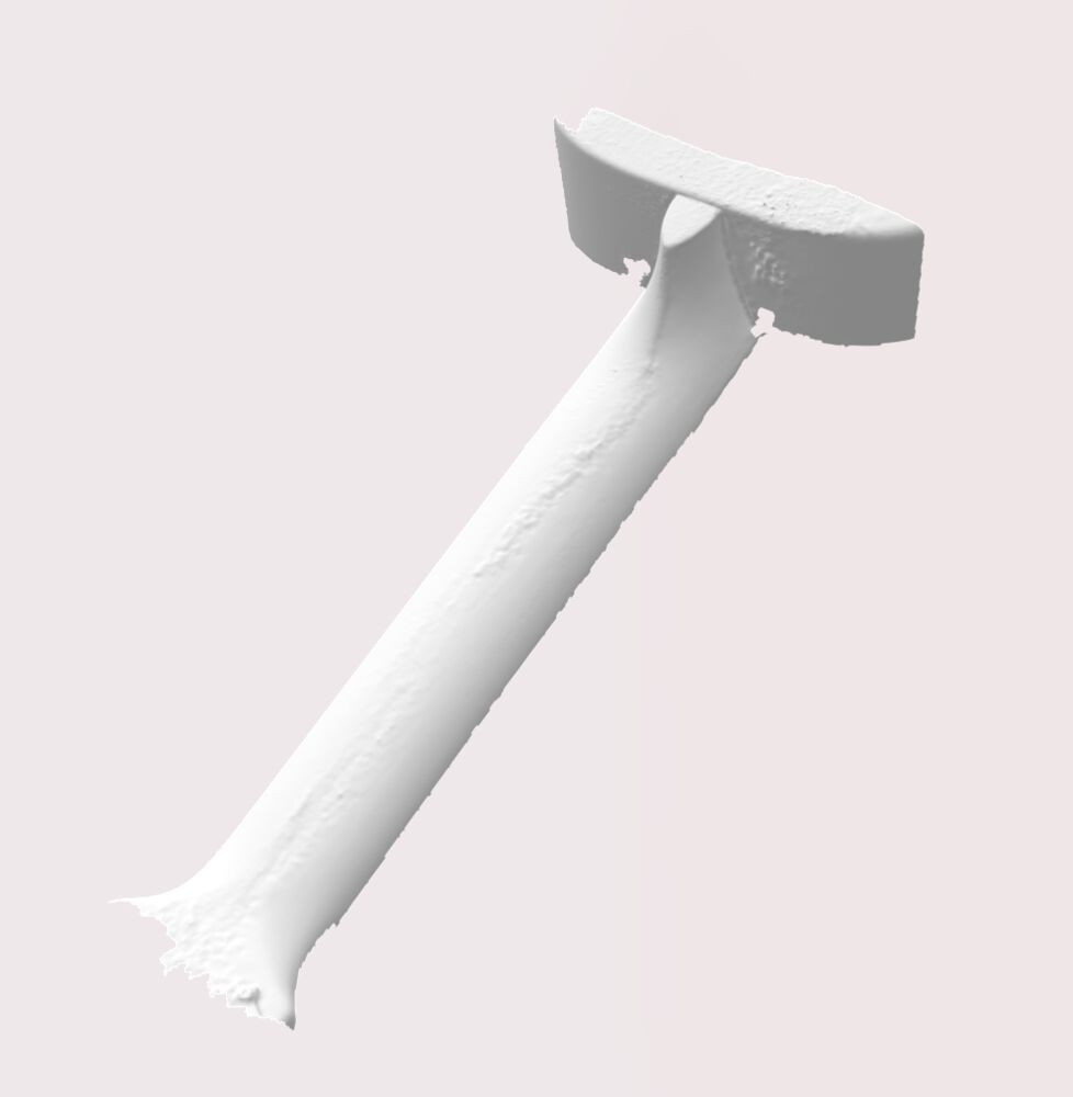
ukulele scan - neck7500poly.stl
Characterising
Group Assginment ‘22
Group Assginment ‘21
Lessons learned
- Dimensional stability: Measuring the 10mm targets in x and y we got 9.8mm, in z we got 10mm.
- Overhang: 0.4mm nozzle happy at 45 degrees will start showing some signs of defect at 50 degrees. 0.6mmm nozzle starts to show defects after 30 degrees.
- Materials: PLA prints easily and clean. PETG shows tendency to go stringy.
- Spans: Clean 20mm span, some sag at 25mm.
- Gap test: Only a single part stuck. Parts with more that 0.1mm gap all free.
3D Scanning on the cheap
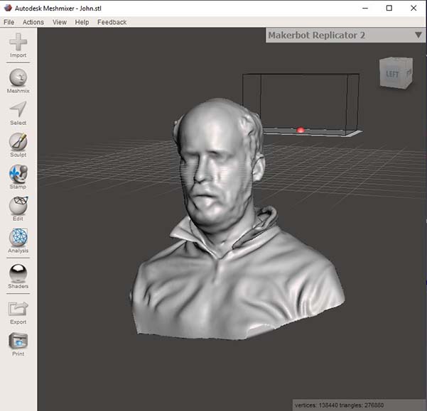
Grabbed a scan of my head from file. This was produced using a 3D Sense, now obsolete and hard to support, we have one laptop that will still connect to it. This is something we need to resolve before we run another cycle.
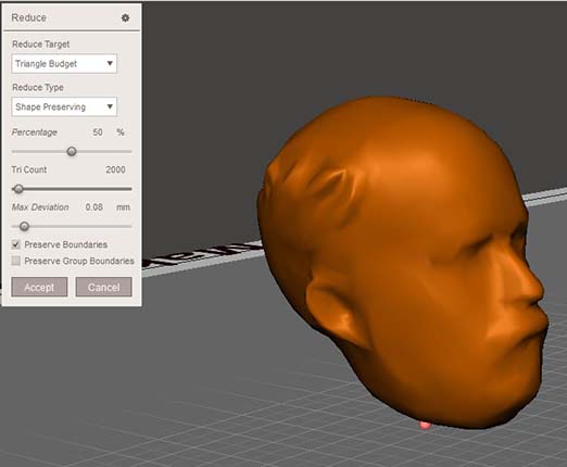
The scan was then processed it in Meshmixer to ‘Select’ and ‘Discard’ the shoulders and then ‘Reduce’ the number of triangles.
We reduced the complexity of the model, as it seems that FreeCAD is not really optimised for importing and handling complex meshes.
This will be composed with other parts later.
Between Standalone and One in every pocket…
The 3D Sense is now an unsupported device. It’s hard to get running and activated. Looking for a similar replacement has proved difficult. It looks like we may be in the no man’s land between affordable standalone devices and having a scanner in every pocket. Recent iPhones and iPads to my knowledge can utilise their depth scanning sensors to produce 3D scans. The hardware will become ever more ubiquitous. Until then it’s tricky to know what to put in place to have a scanning provision in the lab.
More expensive scanning
You may have a more expensive scanner in your lab. We have a, now 6 year old, Artec Spider.
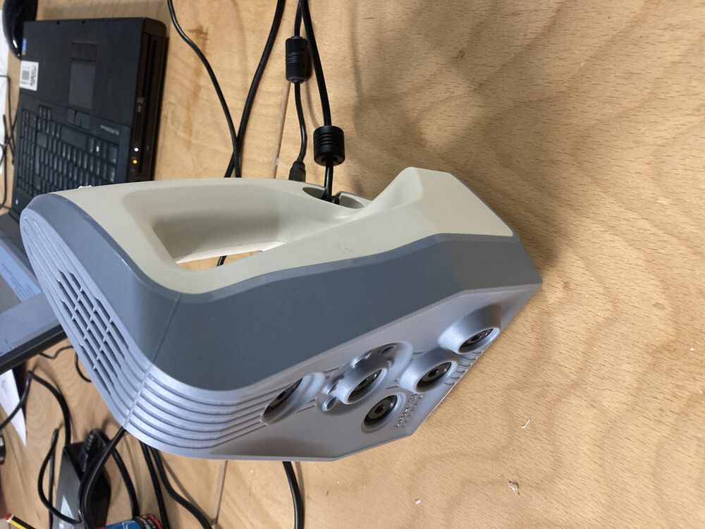
It’s a machine with a steep learning curve. Where with a 3D Sense you make a single scan and export. Artec Studio, makes available a workflow where you can make multiple scans, align and fuse them.
Setting up the scanner you need to let it warm up, and you might consider running a calibration routine with the setup and target provided:
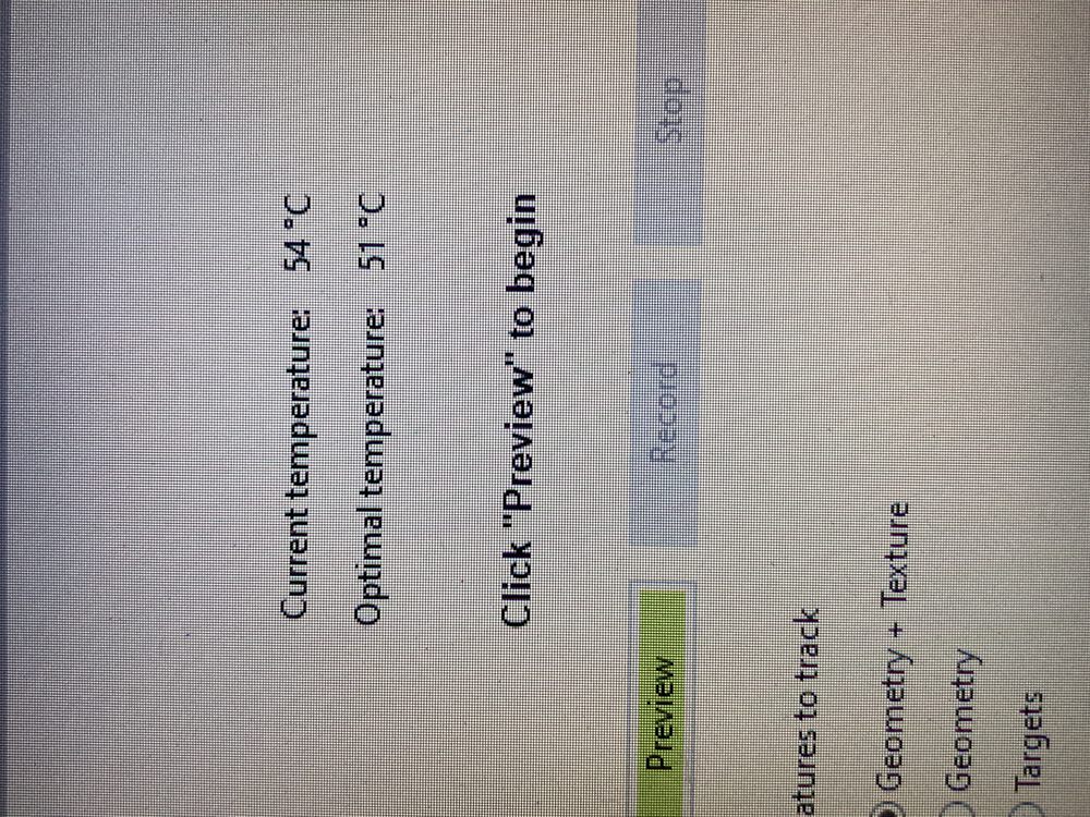

Once you get there you can start to scan.
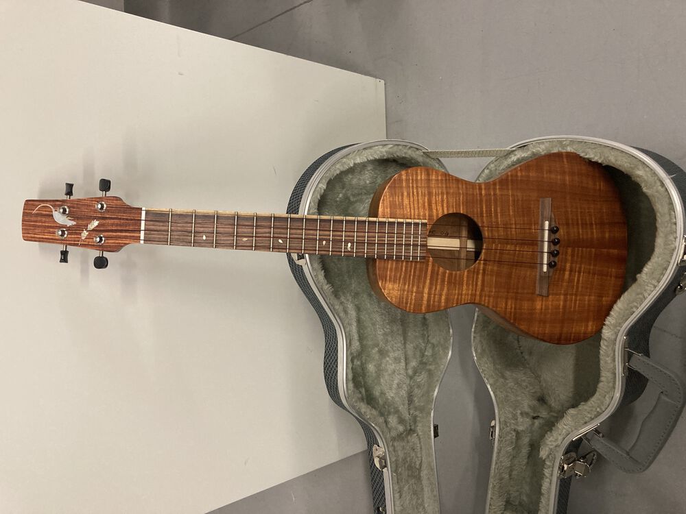
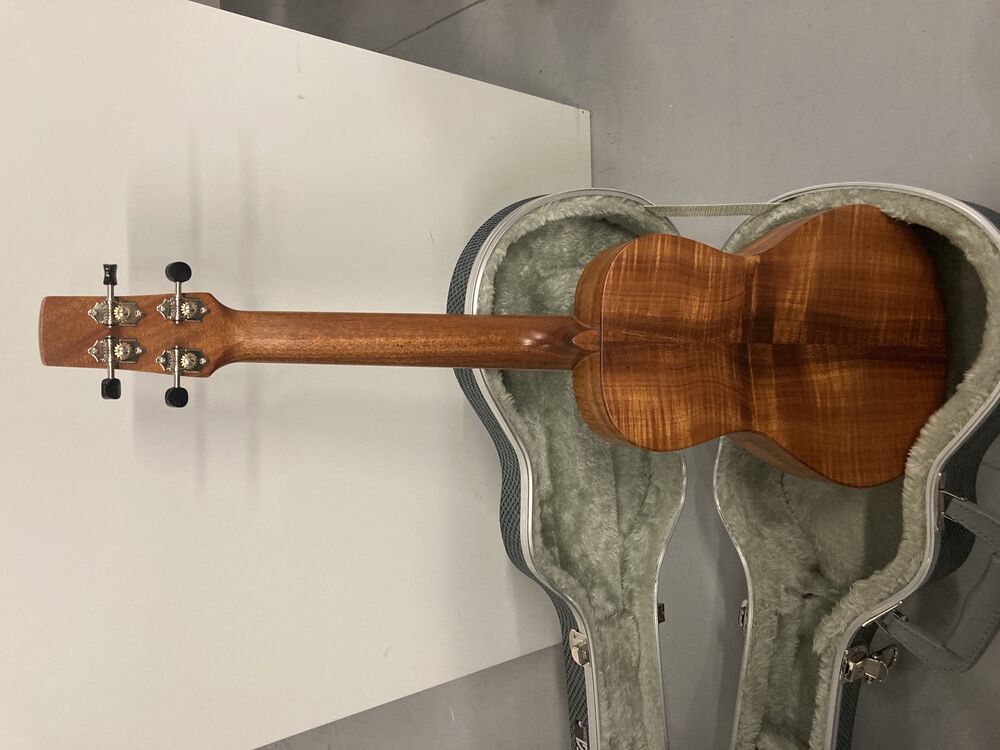
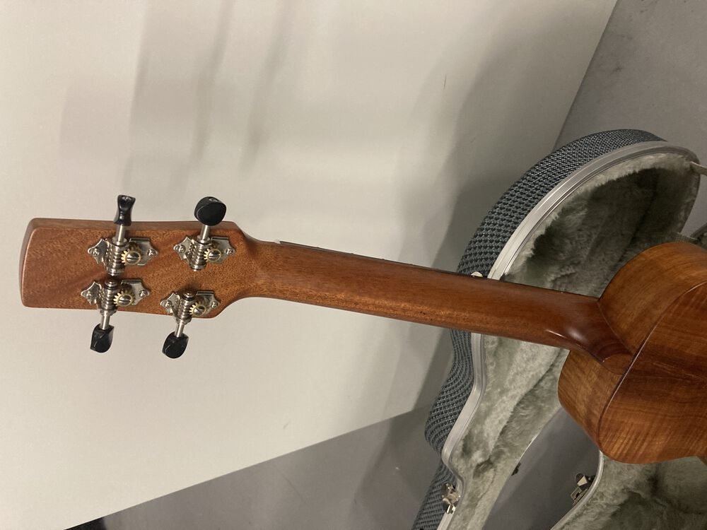
My target for the day was the neck of a hand built Ukulele. I’d like to CNC some parts for my next instrument, including the neck. But it’s a hard thing to model. Making one with hand tools you get to ‘feel’ the curves as they emerge. I’d like a scan of a good neck to form the basis of a 3D model for a new neck.
Artec Studio os a complex piece of sotware designed for industry, it’s not particularly intuitive and to get the most out of it takes more than a couple of goes.
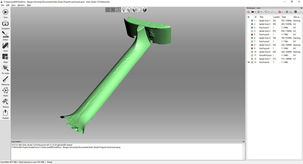
In the screen shot of the interface you can see the end point, I did’t remember to screen grab much along the way. Notable are the tools doen the left hand side that drive the scanning and scan manipultion and merging process. On the right you see a list of scans and fused scans. The raw scans are each larger than 300MB, it’s a data intensive process that needs a more powerful machine to handle the number crunching.
Fundamentally, this tool does not expect you to get a whole scan in one try. The workflow is set up so that you make multiple scans of the object, clean up the data then merge scans by picking out common points and letting the tool do it’s thing.
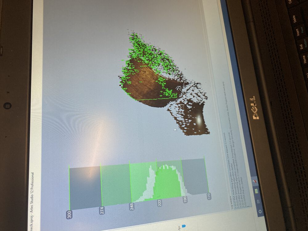
Start off by grabbing multiple scans of the part to produce your data sets:
The individual scan process is much like any other, you have a depth indicator helping you as your scanned data emerges on screen:
When you start to add multiple scans it starts to get a bit more complicated:
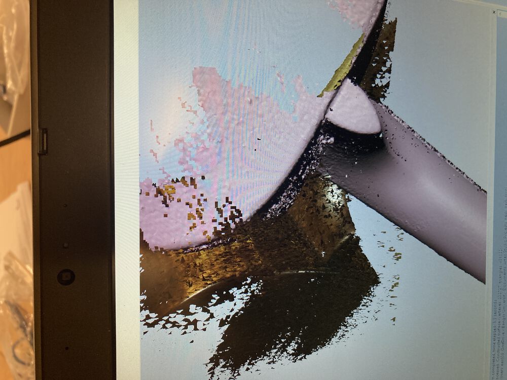
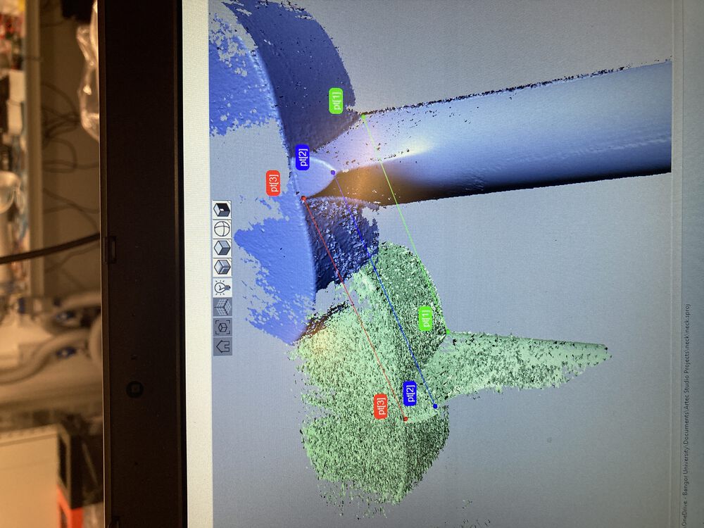
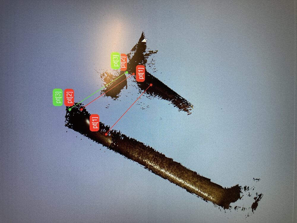
Then start the process of aligning and fusing your scans involves picking out common points:
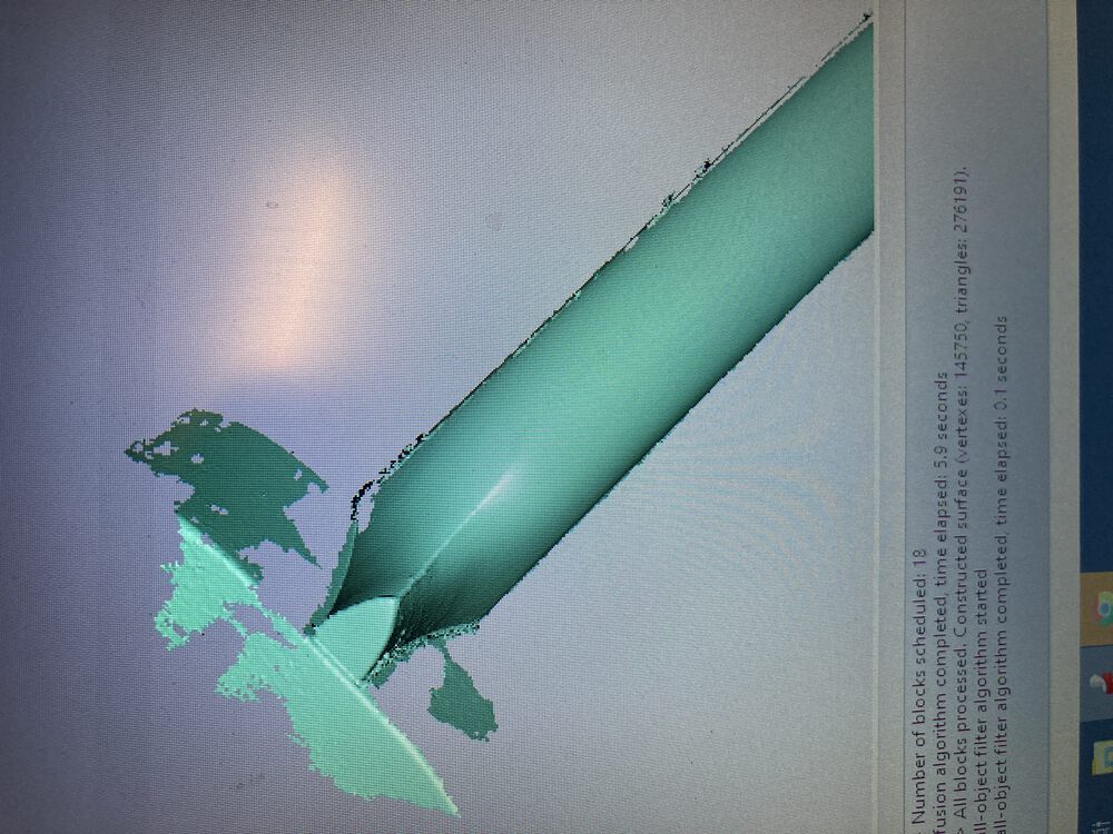
The outcome can then be exported as a mesh. (.stl proved to be a bigger file than .ply)
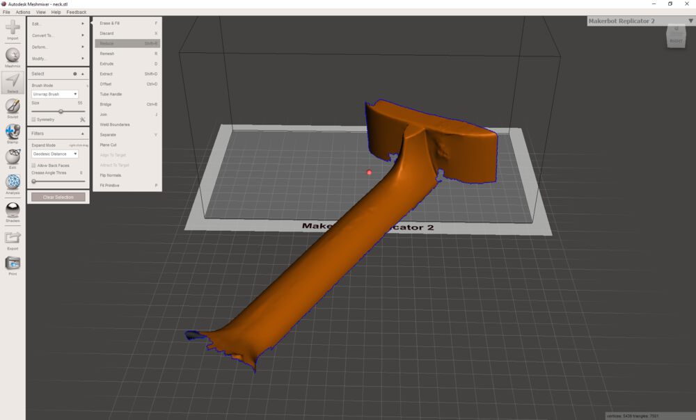
I used Meshmixer to reduce the size of the .stl file exported by Artec Studio. Handy hint, do a select all, CTRL-A and you’ll get a menu of editing tools pop up:
The scan reult is not entirely smooth, mainly due to me not knowing the tools in depth.
A Print Only Object
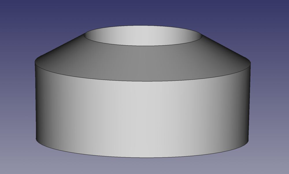
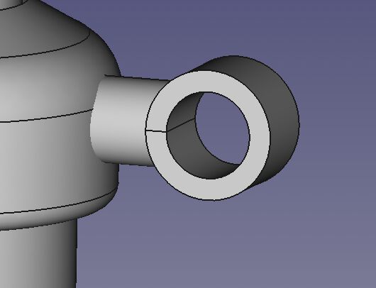
For this exercise I decided to trap a ring on a second part. The Inner Diameter of the moving ring is smaller than the parts on either end of the axle. This could not normally be assembled without one or other of the parts being split with suitable fastenings, but we can print it in one go.
We do however need to carefully consider the 3D printing process in relation to the parts that we want to design. At some point parts are going to overhang, either requiring support structures to print. But if we use support structures with our single material printers, we will get artefacts on the surfaces where the supporting material is to be removed. We need to make sure that those surfaces do not form part of our sliding joints.
To achieve this we look at our printed samples and form our joint from angles that we know can print without support. The parts can be suspended from outer edges with Cura’s Tree support feature, whilst the inner surfaces, printed at a self supporting angle, will be free of any support structure related artefacts.

Design
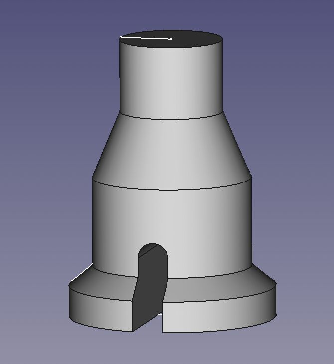
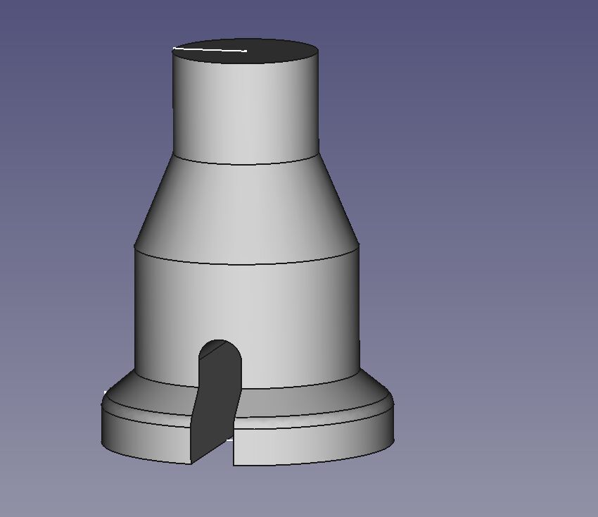
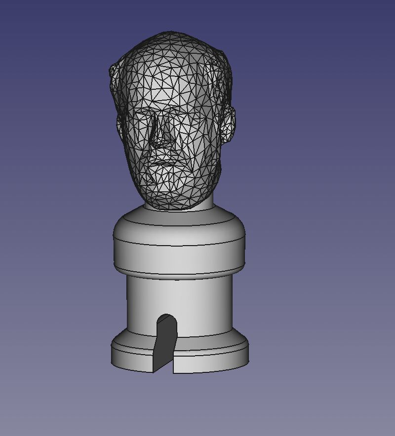
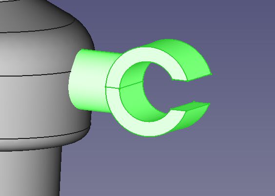
The 3D scan prepared earlier is imported into our model and added to a simple robot body. The body is formed by a revolved sketch that has a boolean subtraction taken out of the base. The collar of the arms structure is another revolved sketch. Arms are simple forms.
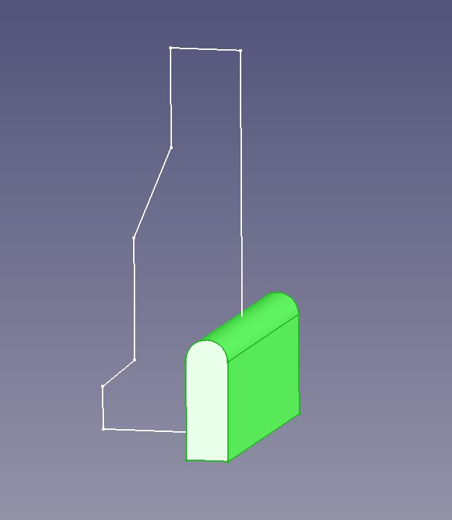
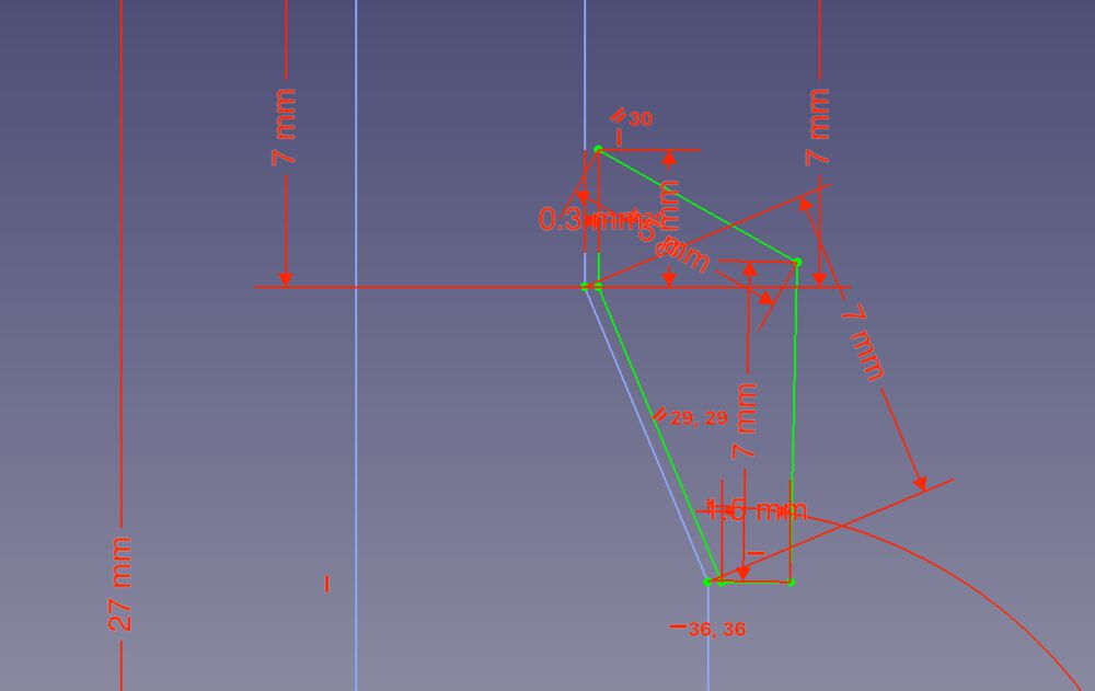
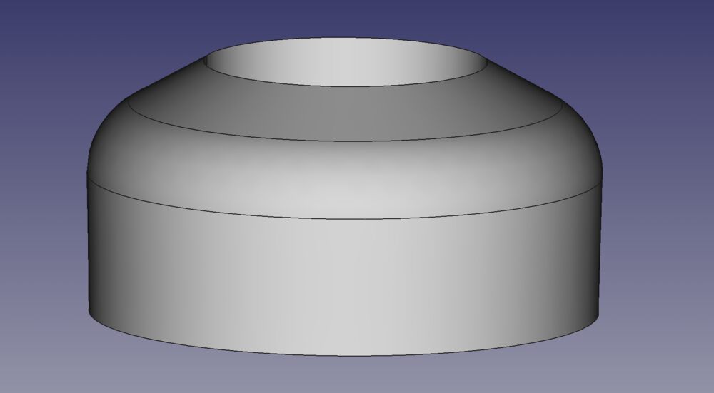
Notice that the collar sketch is constrined to the base sketch. Because the joint is free to slide up and down, the precise distance between the two surfaces is not critical, so long as they do not fuse during printing. The angle of the same surfaces has been selected for a clean un-supported print.
From our lessons learned we know that we need a gap larger than 0.1mm to prevent fusing of the parts. We settled on 0.3mm to provide a safe margin.
 Revolved those and then added some primitives, cylinders, and a few boolean operations later we have some arms added.
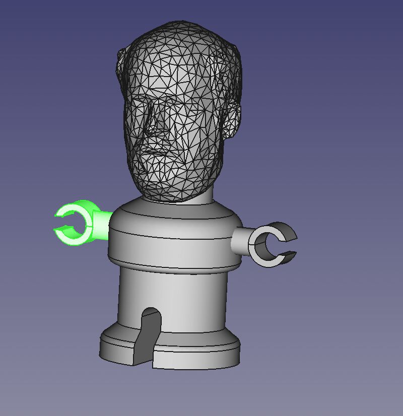
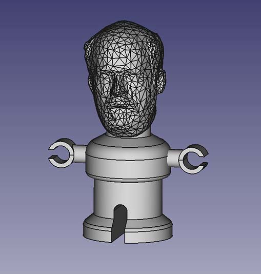 The head scan was imported as a mesh, converted to a shape and then made solid.
In some detail
It always starts with a sketch, this time to one side of the y axis at x=0
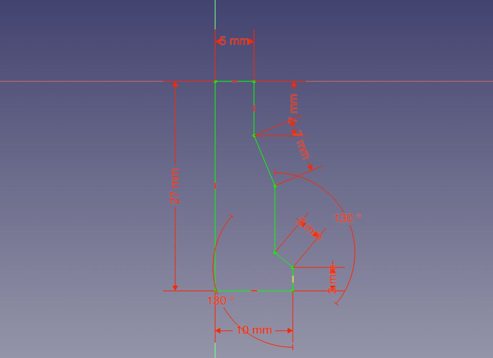
so that we can revolve the part
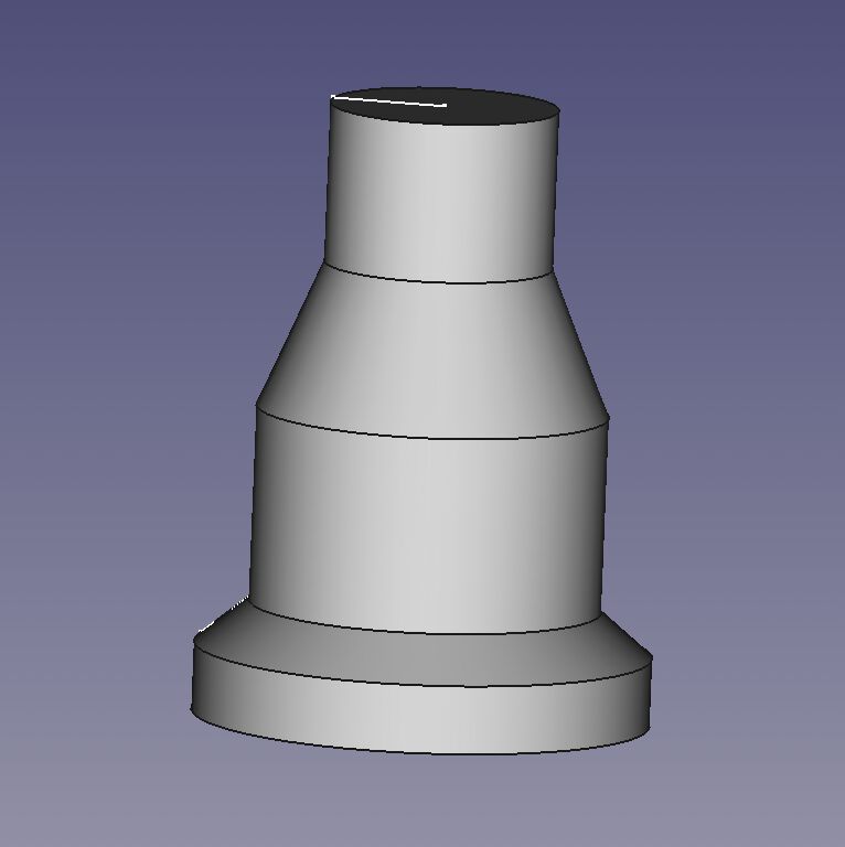
create a second part to act as a tool
and cut it from the revolve
before smoothing some edges with a fillet
the second sketch is made with reference to the first so that we have the gap suggested by our research
another revolve
and more fillets
including the imported head we’re getting closer
arms and hands start out as primitive cylinders
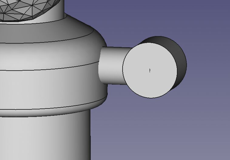
cut a cylinder out
then cut a cube out
and mirror for by lateral symmetry
Cura then Print
We opened the .stl in Cura to slice ready for print. In the most part we used the default settings for PLA.
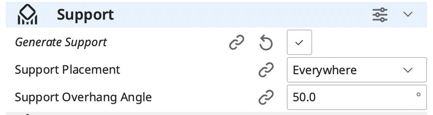
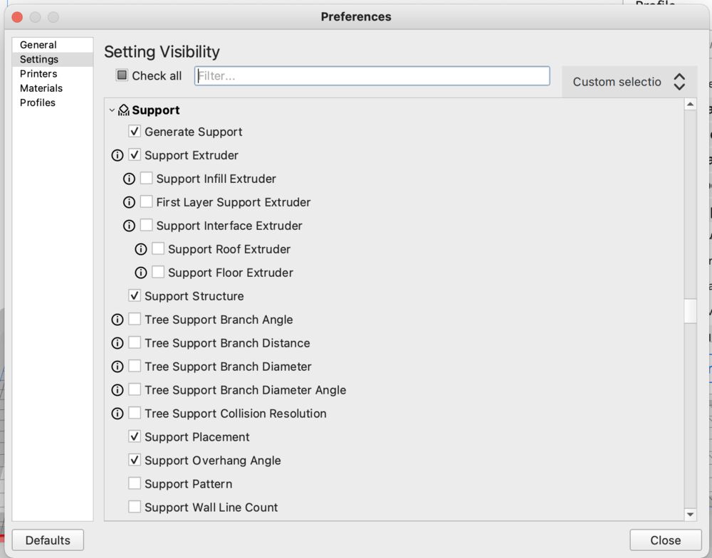
Except that we didn’t want to put generic support on in case it filled the gap between parts. So we made use of Tree support. For a long time this has been an experimental setting, and although it’s now more mature it’s not imediately available. To access it you need to go into your settings, click on the slider menu icon, and enable ‘Support Structure’
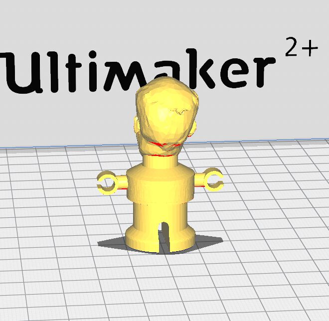
Without:
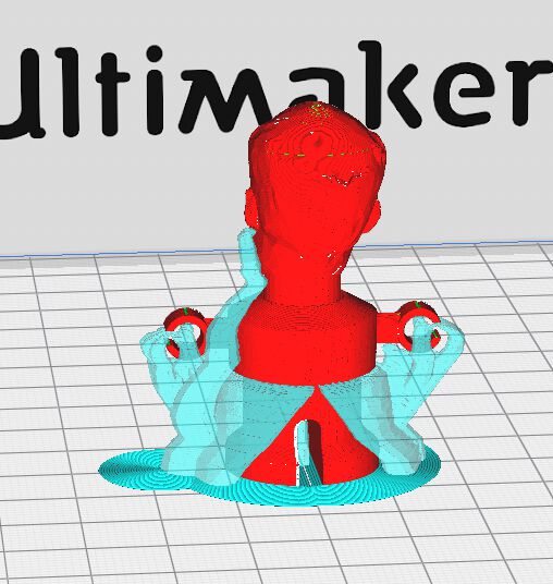
Switching it on:
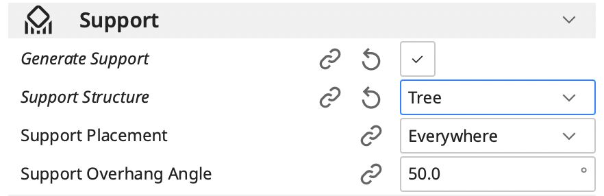
With tree support available:
Next we jit the Sice button, before and after slicing:
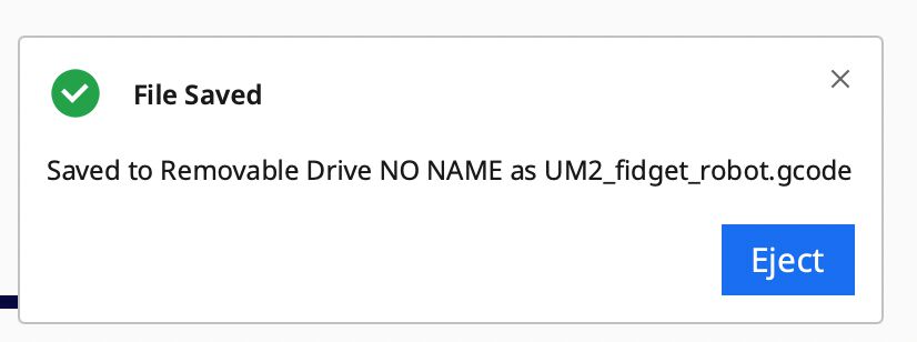
The we tranfer to the printer via SD memory card:

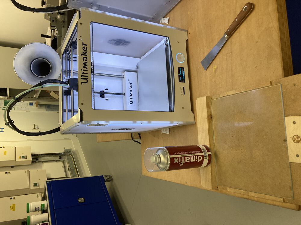
The printer used a glass plate, we add some spray adhesive:
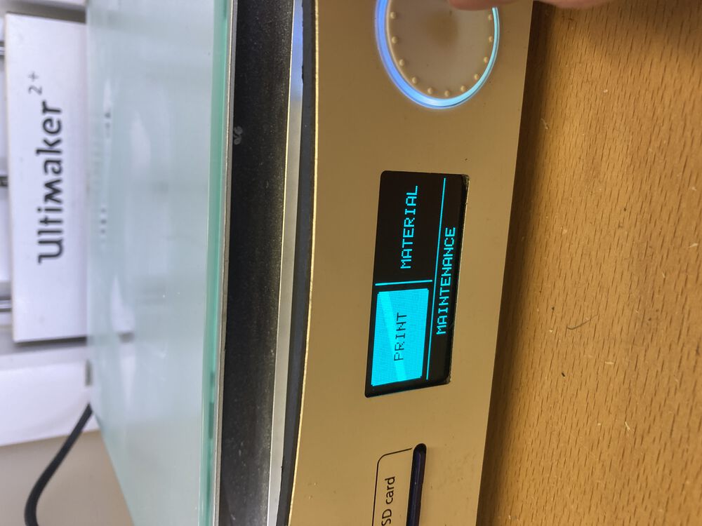
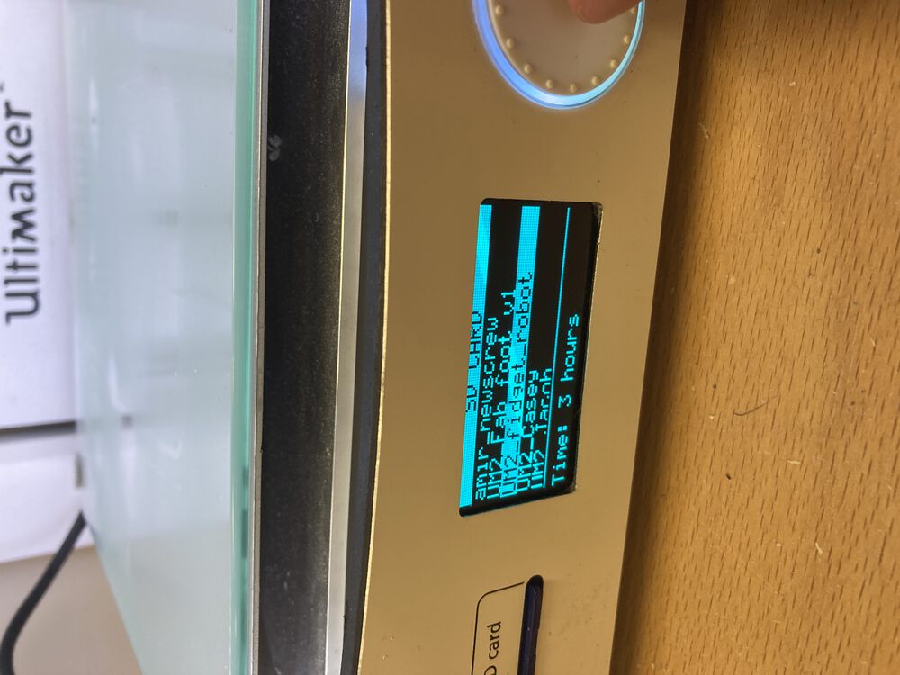
Then we use the menu system to find the file and set it going

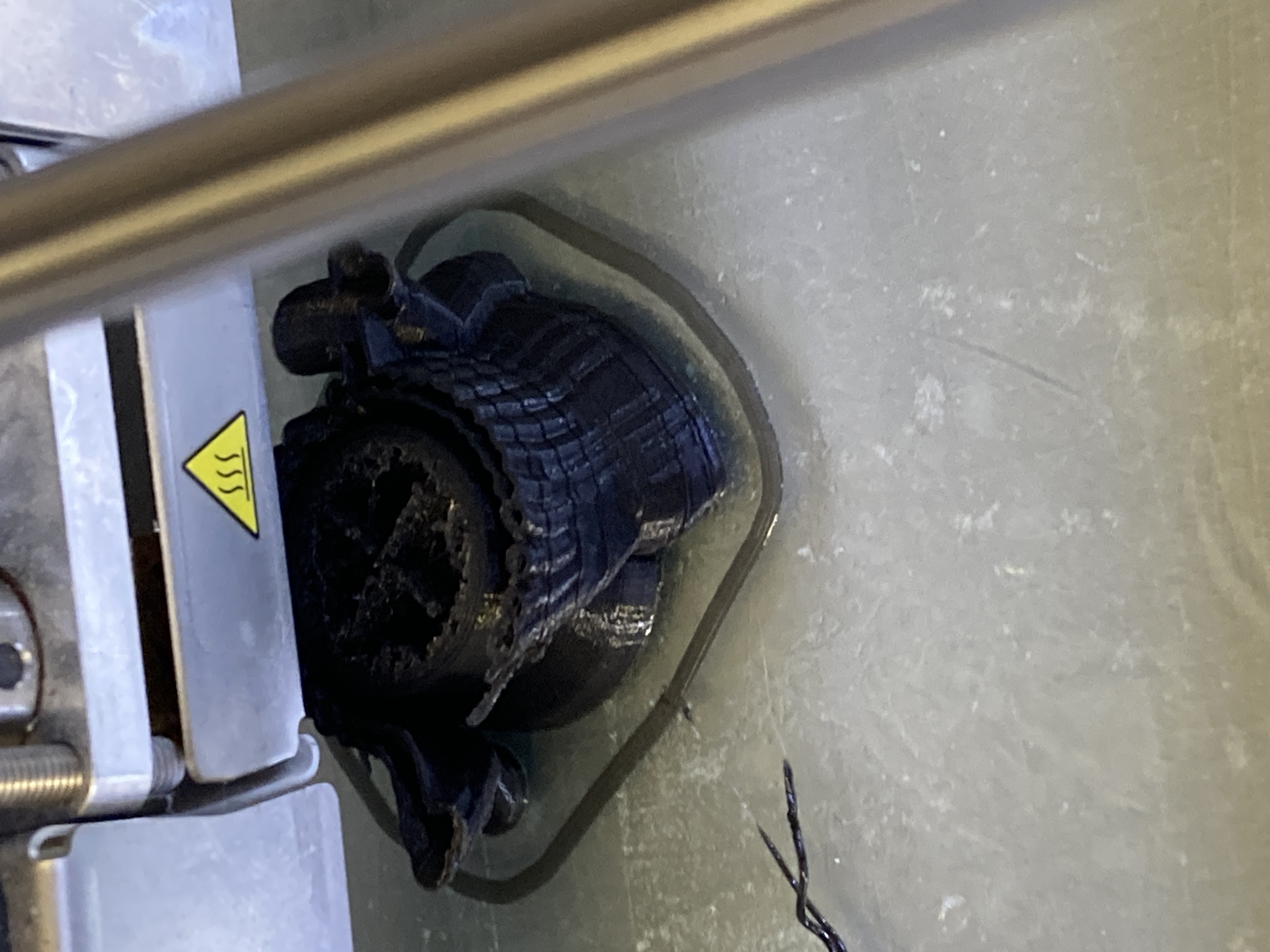
Part with support mid print:
With support removed:
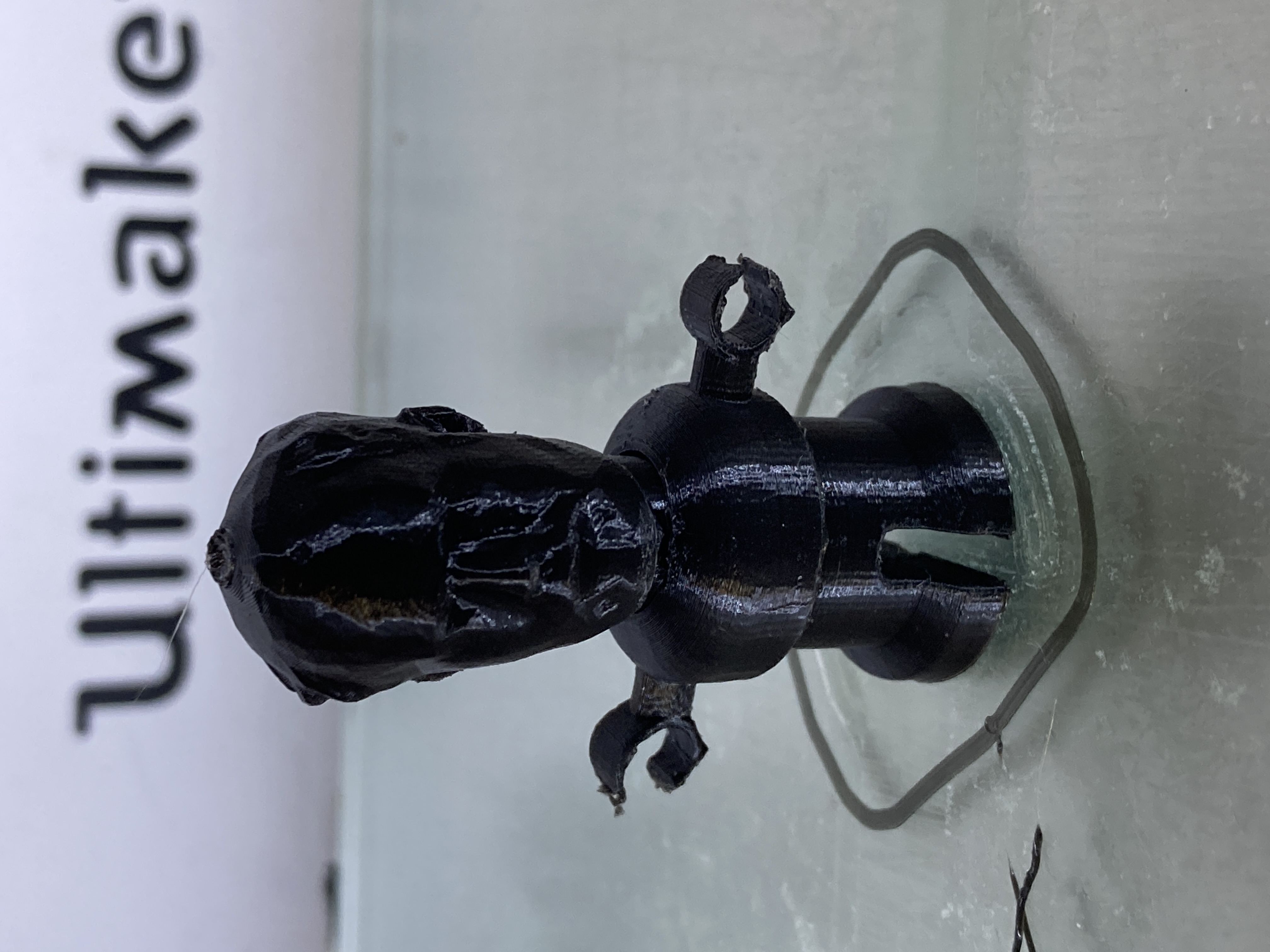
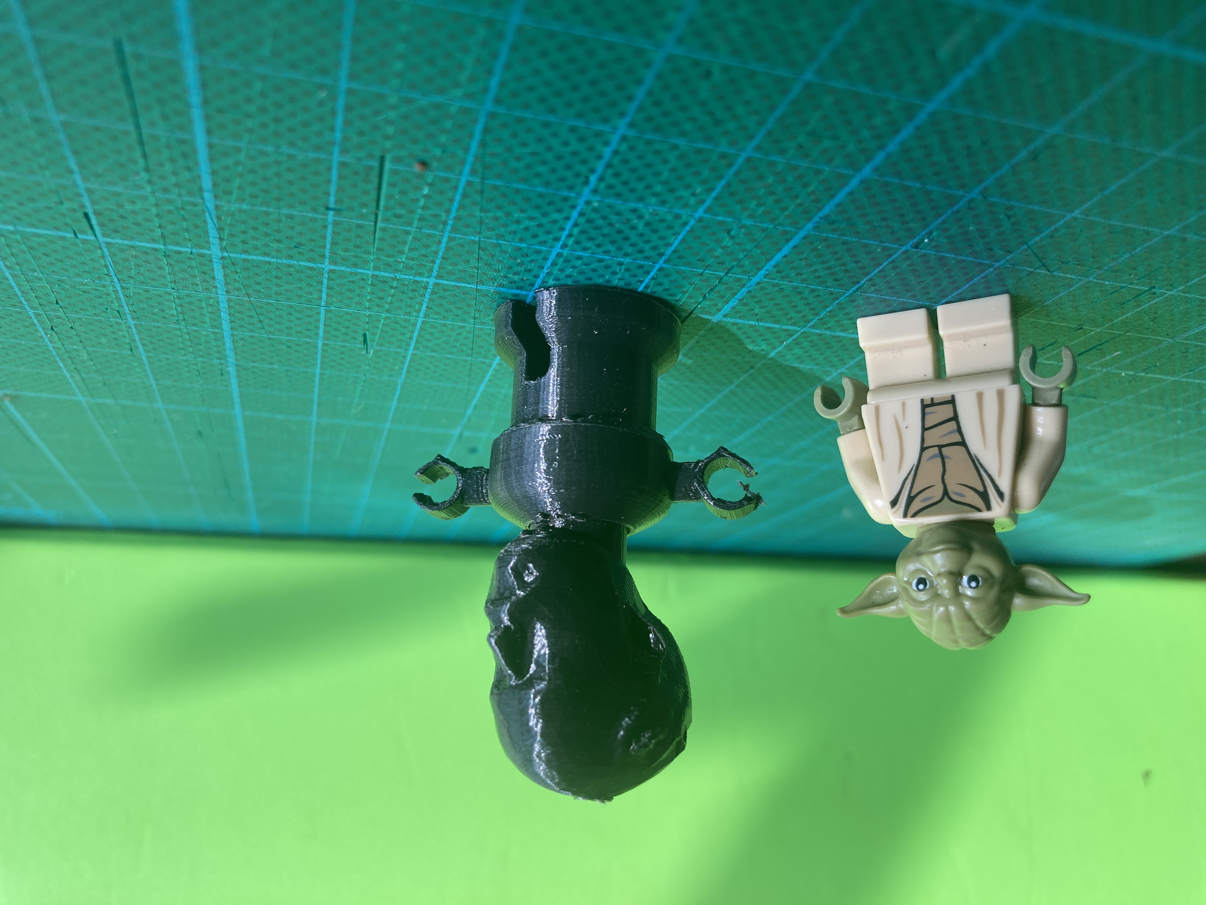
Hero shots…
Lego for reference.